EP1998054A2 - Cylindre pneumatique avec amortissement à réglage automatique en position finale et procédé - Google Patents
Cylindre pneumatique avec amortissement à réglage automatique en position finale et procédé Download PDFInfo
- Publication number
- EP1998054A2 EP1998054A2 EP08156234A EP08156234A EP1998054A2 EP 1998054 A2 EP1998054 A2 EP 1998054A2 EP 08156234 A EP08156234 A EP 08156234A EP 08156234 A EP08156234 A EP 08156234A EP 1998054 A2 EP1998054 A2 EP 1998054A2
- Authority
- EP
- European Patent Office
- Prior art keywords
- damping
- cylinder
- pressure
- piston
- cylinder piston
- Prior art date
- Legal status (The legal status is an assumption and is not a legal conclusion. Google has not performed a legal analysis and makes no representation as to the accuracy of the status listed.)
- Granted
Links
- 238000000034 method Methods 0.000 title claims abstract description 7
- 238000013016 damping Methods 0.000 claims abstract description 114
- 238000009423 ventilation Methods 0.000 claims abstract description 6
- 238000006073 displacement reaction Methods 0.000 claims description 35
- 238000013022 venting Methods 0.000 claims description 22
- 238000007789 sealing Methods 0.000 claims description 8
- 238000011144 upstream manufacturing Methods 0.000 abstract 1
- 230000003044 adaptive effect Effects 0.000 description 8
- 230000001419 dependent effect Effects 0.000 description 5
- 230000000750 progressive effect Effects 0.000 description 4
- 230000010355 oscillation Effects 0.000 description 3
- 239000006096 absorbing agent Substances 0.000 description 2
- 230000001105 regulatory effect Effects 0.000 description 2
- 230000035939 shock Effects 0.000 description 2
- 230000006835 compression Effects 0.000 description 1
- 238000007906 compression Methods 0.000 description 1
- 230000000694 effects Effects 0.000 description 1
- 239000012530 fluid Substances 0.000 description 1
- 230000005484 gravity Effects 0.000 description 1
- 230000003993 interaction Effects 0.000 description 1
- 230000036316 preload Effects 0.000 description 1
Images

Classifications
-
- F—MECHANICAL ENGINEERING; LIGHTING; HEATING; WEAPONS; BLASTING
- F15—FLUID-PRESSURE ACTUATORS; HYDRAULICS OR PNEUMATICS IN GENERAL
- F15B—SYSTEMS ACTING BY MEANS OF FLUIDS IN GENERAL; FLUID-PRESSURE ACTUATORS, e.g. SERVOMOTORS; DETAILS OF FLUID-PRESSURE SYSTEMS, NOT OTHERWISE PROVIDED FOR
- F15B15/00—Fluid-actuated devices for displacing a member from one position to another; Gearing associated therewith
- F15B15/20—Other details, e.g. assembly with regulating devices
- F15B15/22—Other details, e.g. assembly with regulating devices for accelerating or decelerating the stroke
- F15B15/223—Other details, e.g. assembly with regulating devices for accelerating or decelerating the stroke having a piston with a piston extension or piston recess which completely seals the main fluid outlet as the piston approaches its end position
Definitions
- the subject invention relates to a pneumatic cylinder with a self-adjusting end position damping with a cylinder housing in which a movable cylinder piston is arranged, which is acted upon by pressure on one side and by the movement of the cylinder piston in the region of the end position of the cylinder piston from the non-pressurized side the cylinder piston limited damping volume is formed, and a method for self-adjusting end position damping.
- a cushioning is often used to prevent the piston strikes in the end position against the cylinder housing or against a stop.
- the aim of the end position damping is therefore to reduce the speed of a moving mass (piston + load), whose center of gravity is usually in the cylinder axis, to a level at which neither the cylinder nor the machine in which the cylinder is installed, damaged or impacted by initiated impacts.
- the volume can not be dissipated in the same time in which the piston retracts, which is why there is a pressure increase in this chamber.
- the piston is decelerated by this pressure and should therefore not hit the cylinder cover or an end stop, but slowly retract with the time-delayed escape of air.
- the valve needle is set during commissioning of the cylinder.
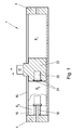
- This form of end position damping can be found in many pneumatic or hydraulic cylinders which have a cushioning, such as in a rodless pneumatic cylinder 1 as in Fig. 1 shown.
- the disadvantage of this cushioning is that only a certain kinetic energy can be reduced by the fixed setting of the valve needle.
- path-dependent Endlagendämpfonne are known, such as from the EP 949 422 A1 , which change an exhaust air cross-section as a function of the piston position and thus can specify a progressive damping curve.
- this Dämpfverlauf is dependent on the fixed geometry and can thus be optimal only for a certain combination of mass and speed. If the pneumatic cylinder is operated away from the optimum operating point, eg if the working pressure (and thus the speed) changes or if another load is moved, the damping is no longer optimal. But this is exactly the case in practice, as it has been shown that the positions where the pressure peaks occur are different depending on the load and speed.
- pneumatic shock absorbers are known, for example from the DE 37 40 669 A1 , with an outlet valve, over which the air compressed during a damping movement of the piston is discharged.
- a valve tappet is biased by the working pressure and a spring force.
- the exhaust valve opens abruptly and the compressed air is released via a throttle.
- the objective of the subject invention has set itself the task to provide a cushioning of a pneumatic cylinder, and an associated method, which automatically to different operating parameters, such as. Mass, speed and working pressure, adjusted to achieve a wide range optimal damping and which is simple and inexpensive designed.
- the end position damping comprises a displacement which is limited by a movable lifting element and a part of the pneumatic cylinder, wherein the displacement is connected via a connecting channel with the cylinder piston acting on the working pressure or applied in an outlet venting pressure and the Lifting element is acted upon by a damping channel from the pressure in the damping volume, in the connecting channel before the displacement of a check valve is arranged, which blocks in the direction of the working pressure and the venting pressure and that a venting channel is provided, which can be opened with the movable lifting element is and which is connected to an exhaust duct.
- the inventive method results from the fact that in the damping volume by the movement of the cylinder piston, a damping pressure is applied to a lifting element is acted upon, the lifting element is moved by the damping pressure against a completed in a displacement, acted upon by the working pressure or the venting pressure fluid volume and through the movement of the lifting element is opened a venting channel.
- the spring constant of this gas spring changes independently depending on the prevailing pressures and it is achieved a constant damping effect even at different operating pressures and different kinetic energies.
- the venting pressure is used in the adaptive gas spring, since the pressure profile on the vent side shows a more pronounced dependence on the travel speed of the cylinder piston and is thus better suited as a controlled variable.
- the invention thereby increases the comfort, reliability and ease of use of the pneumatic drive.
- the automatic adjustment of the end-of-stroke damping to the operating conditions also eliminates the costs for manual adjustment and reduces cycle times.
- the damping volume is advantageously formed by a in the axial direction in the cylinder housing extending damper pin is arranged in the region of the end stop of the cylinder piston and the cylinder piston is designed with a recess accommodating the damping pin. Characterized the cylinder volume is divided when retracting the damper pin in the recess for forming the damping volume.
- the damping volume may also be formed by arranging an exhaust duct laterally on the cylinder housing and axially spaced from the cylinder cover.
- the lifting element is designed as guided in the displacement mounted damping piston.
- the displacement or the damping piston can, depending on the structural design, either be arranged in a cylinder cover closing off the pneumatic cylinder or in the cylinder piston.
- the lifting element may also be a sealing element between the damping pin and the cylinder piston, wherein the sealing element is hollow and is arranged in the cylinder piston.
- a vent opening may be provided on the pneumatic cylinder which is connected to the damping volume.
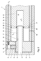
- Fig. 2 is an end, here the completed by the cylinder cover 4 end of a pneumatic cylinder 1, here for example a rodless pneumatic cylinder, shown with a self-adjusting end position damping according to the invention in detail.
- the cylinder piston 22 is, for example via a carriage, connected to a mass m and moves under pressurization p 1 on one of its sides at a speed v in a cylinder housing 15 in the direction of the mechanical end stop (in the region of the cylinder cover 4).
- the cylinder piston 22 is sealed relative to the cylinder housing in a known manner by means of sealing elements 20.
- the direction of movement is in Fig. 2 indicated by the arrow.
- the displaced by the movement of air on the non-pressurized side of the cylinder piston 22 is discharged via a channel 3 in the cylinder cover 4 and a connection not shown here.
- a recess 23 is provided which can receive a axially extending into the cylinder housing 15 Dämpfzapfen 18.
- the damping pin 18 is arranged in this example on the cylinder cover 4 and in the end region or in the region of an end position of the cylinder piston 22 of the pneumatic cylinder 1, resulting in a Dämpf Scheme.
- An outlet channel 3 extends here in the axial direction through the cylinder cover 4 and through the damping pin 18.
- such a damping volume 19 can also be formed differently, in particular without damping pin 18, for example by the outlet channel 3 being laterally spaced apart from the cylinder cover 4 in the axial direction is arranged on the cylinder housing 15, as in Fig. 2 indicated by dashed lines and indicated by reference numeral 3a.
- the outlet channel 3a is closed during the movement of the cylinder piston 22, resulting in the end position of the cylinder piston 22 between the cylinder cover 4 and cylinder piston 22 again a corresponding damping volume 19.
- a displacement 9 is provided - here a simple bore, which is closed by a disc 10.
- the displacement 9 is limited by a lifting element, here a damper piston 7, the movable (as indicated by the double arrow in Fig. 2 indicated) and guided in the displacement 9 is arranged.
- the displacement 9 is connected here via a channel 11 in the cylinder cover 4 and a cylinder housing 15 arranged in the connecting channel 14 with the working pressure p 1 on the pressurized side of the cylinder piston 22.
- a check valve 12 is arranged that blocks in the direction of the working pressure p 1 .
- the damping piston 7 is therefore pressurized on one side by the force acting in the displacement 9 working pressure p 1 .
- the opposite side 6 of the damper piston 7 is executed stepped in this example and is connected via a damping channel 16 with the damping volume 19.
- the damper piston 7 closes a venting channel 5 arranged in the cylinder cover 4 and connected to the outlet duct 3.
- the damper piston 7 may be provided for sealing against the cylinder cover 4 with throttling grooves 8. Instead of throttling grooves 8 but also any other sealing elements may be provided.
- a targeted leakage can be provided via the throttling grooves 8 or the other sealing elements at this point for pressure reduction in the displacement 9.
- vent the displacement 9 between two strokes if necessary via other suitable means, such as a valve or throttle, or to pressurize it with the new working pressure p 1 .
- end position damping can also be provided on the other side of the pneumatic cylinder, so that the opposite movement is endlagengedämpft accordingly.
- the same arrangement can also be provided on the other side and the working pressure then acting is supplied via the second connecting channel 2 to the second displacement 9.
- the displaced air is discharged through the outlet channel 3 on the side of the cylinder piston 22 facing away from the pressurized side.
- the outlet channel 3 is advantageously dimensioned so that the entire displaced air without backflow (and thus without associated pressure increase) can be dissipated.
- the opening function behaves almost linearly to the pressure.
- the spring constant of this gas spring is determined by the volume and pressure of the air volume. If the working pressure varies, so does the spring constant of the gas spring changes. Changes the kinetic energy of the cylinder piston 22, for example, by a higher speed v or another mass m, adapts itself to the new conditions via different pressure ratios of the stroke of the damping element 7 and thus also the damping behavior. This works in a certain energy range, whereby the maximum damping energy must not be exceeded. At different working pressures, the characteristic of the damping function shifts.
- the oscillation is caused by the driving up of the cylinder piston 22 on the air cushion, which is formed in the damping chamber 19, since the trapped air can not escape.
- This oscillation can be counteracted, for example, by deliberately introducing one (or more) vent opening (s) 17, for example in the damping journal 18 or in the cylinder housing 15.
- the vent 17 can be adjusted in its shape, location and size the circumstances, such as the structural design or the expected kinetic energies.
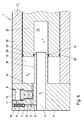
- Fig. 3 an alternative embodiment of a self-adjusting end position damping according to the invention is shown.
- the displacement 9 in the cylinder piston 22 is arranged, as well as the connecting channel 14, the check valve 12, the damping channel 16 and the venting channel 5.
- the function of this cushioning is identical to that with reference to Fig. 2 described.
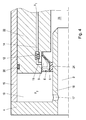
- Fig. 4 shows a further possible embodiment of the invention.
- the lifting element is designed as an elastic damping seal 24.
- the damping seal 24 is arranged on the recess 23 of the cylinder piston 22.
- the damping seal 24 is hollow and thus forms a volume between the cylinder piston 22 and the damper seal - the displacement 9.
- the damping seal 24 is compressed, as in Fig. 4 indicated by dashed lines.
- the damping seal 24 lifts off from the damping pin 18 and creates an annular venting channel 5 between the damping seal 24 and the damping pin 18, through which the air trapped in the damping volume 19 can flow out again.
- the displacement 9 is formed by the pressure load by the working pressure p 1 again a gas spring with progressive spring constant, which counteracts the compression of the damping seal 24.
- the function of this embodiment is therefore again identical to that with reference to Fig. 2 described.
- the displacement 9 is always acted upon by the working pressure p 1 .
- a back pressure p 3 is present on the vent side, whose level is lower than that of the ventilation side.
- the displacement 9 is connected in this embodiment via a connecting channel 14 and a channel 11 with the outlet channel 3, in which the venting pressure p 3 is applied.
- a check valve 12 is arranged that blocks p 3 in the direction of the venting pressure.
- the lifting element here again a damping piston 7, can be designed with piston surfaces of different sizes.
- the cylinder piston 22 ascends with the damping seal 21 onto the damping pin 18, the pressure p 2 in the damping volume 19 and the venting pressure p 3 in the outlet channel 3 are the same.
- the venting pressure p 3 is via the connecting channel 14, the check valve 12 and the channel 11 in the displacement 9 at. If the damping seal 21 closes off the damping volume 19, the venting pressure p 3 in the outlet channel 3 drops sharply. In displacement 9, however, this pressure is maintained due to the check valve 12.
Landscapes
- Engineering & Computer Science (AREA)
- Physics & Mathematics (AREA)
- Fluid Mechanics (AREA)
- Mechanical Engineering (AREA)
- General Engineering & Computer Science (AREA)
- Actuator (AREA)
- Fluid-Damping Devices (AREA)
Applications Claiming Priority (2)
| Application Number | Priority Date | Filing Date | Title |
|---|---|---|---|
| AT8282007A AT504592B1 (de) | 2007-05-24 | 2007-05-24 | Pneumatikzylinder mit einer und verfahren zur selbsteinstellenden endlagendämpfung |
| AT7142008A AT505441B1 (de) | 2007-05-24 | 2008-05-05 | Pneumatikzylinder mit einer und verfahren zur selbsteinstellenden endlagendämpfung |
Publications (3)
| Publication Number | Publication Date |
|---|---|
| EP1998054A2 true EP1998054A2 (fr) | 2008-12-03 |
| EP1998054A3 EP1998054A3 (fr) | 2012-08-15 |
| EP1998054B1 EP1998054B1 (fr) | 2014-08-13 |
Family
ID=39829770
Family Applications (1)
| Application Number | Title | Priority Date | Filing Date |
|---|---|---|---|
| EP08156234.0A Not-in-force EP1998054B1 (fr) | 2007-05-24 | 2008-05-15 | Cylindre pneumatique avec amortissement à réglage automatique en position finale et procédé |
Country Status (2)
| Country | Link |
|---|---|
| US (1) | US8596431B2 (fr) |
| EP (1) | EP1998054B1 (fr) |
Cited By (3)
| Publication number | Priority date | Publication date | Assignee | Title |
|---|---|---|---|---|
| CN102235400A (zh) * | 2010-04-22 | 2011-11-09 | 郑文瑞 | 缓冲装置 |
| DE102011051400B3 (de) * | 2011-06-28 | 2012-06-06 | Parker Hannifin Gmbh | Pneumatikzylinder mit selbstjustierender Endlagendämpfung |
| DE102016002705A1 (de) * | 2016-03-05 | 2017-09-07 | Wabco Gmbh | Pneumatische Schaltvorrichtung eines automatisierten Schaltgetriebes |
Families Citing this family (6)
| Publication number | Priority date | Publication date | Assignee | Title |
|---|---|---|---|---|
| JP5960034B2 (ja) * | 2012-11-21 | 2016-08-02 | 株式会社ショーワ | 圧力緩衝装置および懸架装置 |
| CN103104572A (zh) * | 2012-12-11 | 2013-05-15 | 江苏锐成机械有限公司 | 一种高速机床用防撞液压缸 |
| US9447834B2 (en) * | 2013-09-19 | 2016-09-20 | Dadco, Inc. | Overtravel pressure relief for a gas spring |
| US20150076753A1 (en) * | 2013-09-19 | 2015-03-19 | Dadco, Inc. | Overtravel Pressure Relief For A Gas Spring |
| CN103821790A (zh) * | 2013-11-29 | 2014-05-28 | 安徽凯信机电科技有限公司 | 一种带有缓冲机构的液压缸 |
| JP7447689B2 (ja) * | 2020-06-10 | 2024-03-12 | Smc株式会社 | ガスシリンダ |
Citations (2)
| Publication number | Priority date | Publication date | Assignee | Title |
|---|---|---|---|---|
| DE3740669A1 (de) | 1987-12-01 | 1989-06-15 | Festo Kg | Pneumatischer stossdaempfer |
| EP0949422A1 (fr) | 1998-03-04 | 1999-10-13 | Bümach Engineering International B.V. | Dispositif amortisseur de fin de course |
Family Cites Families (83)
| Publication number | Priority date | Publication date | Assignee | Title |
|---|---|---|---|---|
| DE1039844B (de) * | 1957-05-23 | 1958-09-25 | Pumpenfabrik Urach | Hydraulischer Arbeitszylinder mit Daempfungseinrichtung |
| FR1527946A (fr) * | 1967-04-05 | 1968-06-07 | Cie Parisienne Outil Air Compr | Perfectionnement aux vérins à amortissement |
| SE346468B (fr) * | 1969-02-24 | 1972-07-10 | Lkb Medical Ab | |
| US3613503A (en) | 1969-04-28 | 1971-10-19 | Cessna Aircraft Co | Hydraulic cylinder with pressure control |
| US3889576A (en) * | 1969-06-13 | 1975-06-17 | Sheffer Corp | Locking cylinder with improved locking structure |
| FR2138342B1 (fr) | 1971-05-24 | 1974-03-08 | Poclain Sa | |
| GB1351958A (en) * | 1971-09-14 | 1974-05-15 | Martonair Ltd | Pneumatic actuators |
| FR2182672B1 (fr) * | 1972-05-03 | 1975-03-21 | Poclain Sa | |
| NL182162C (nl) | 1977-01-10 | 1988-01-18 | Hydraudyne Bv | Inrichting voor het hydraulisch of pneumatisch aandrijven en afremmen van een werktuig. |
| ES226859Y (es) * | 1977-03-03 | 1977-11-16 | Marcapasos cardiaco de ritmo controlado por senales de regu-lacion detectadas en las vias yno los receptores nerviosos. | |
| JPS57103947A (en) * | 1980-12-18 | 1982-06-28 | Kuroda Precision Ind Ltd | Pneumatic shock absorber |
| JPS63143392A (ja) * | 1986-12-05 | 1988-06-15 | Toyota Autom Loom Works Ltd | ワツブル式可変容量圧縮機の制御方法 |
| US4830003A (en) * | 1988-06-17 | 1989-05-16 | Wolff Rodney G | Compressive stent and delivery system |
| SE467424B (sv) * | 1990-11-09 | 1992-07-13 | Mecman Ab | Anordning foer aendlaegesdaempning och hastighetsreglering av roerelsen hos en kolv i en tryckmediecylinder |
| US5437285A (en) * | 1991-02-20 | 1995-08-01 | Georgetown University | Method and apparatus for prediction of sudden cardiac death by simultaneous assessment of autonomic function and cardiac electrical stability |
| US5403341A (en) * | 1994-01-24 | 1995-04-04 | Solar; Ronald J. | Parallel flow endovascular stent and deployment apparatus therefore |
| US6039749A (en) * | 1994-02-10 | 2000-03-21 | Endovascular Systems, Inc. | Method and apparatus for deploying non-circular stents and graftstent complexes |
| JPH0893719A (ja) * | 1994-09-20 | 1996-04-09 | Futaba Denki Kogyo Kk | 油圧又は空圧シリンダのストローク調節装置 |
| US5707400A (en) * | 1995-09-19 | 1998-01-13 | Cyberonics, Inc. | Treating refractory hypertension by nerve stimulation |
| DE29517364U1 (de) * | 1995-11-02 | 1996-01-04 | Festo Kg, 73734 Esslingen | Vorrichtung zur Endlagendämpfung |
| US5727558A (en) * | 1996-02-14 | 1998-03-17 | Hakki; A-Hamid | Noninvasive blood pressure monitor and control device |
| SE510463C2 (sv) * | 1996-11-26 | 1999-05-25 | Pos Line Ab | Förfarande och anordning för att eliminera kolvstångsrusning vid start av pneumatisk motor |
| GB9710905D0 (en) * | 1997-05-27 | 1997-07-23 | Imperial College | Stent for blood vessel |
| CH691846A5 (fr) * | 1997-06-20 | 2001-11-15 | Ecole Polytech | Implant de dilatation intravasculaire à déflecteur. |
| US6663617B1 (en) * | 1998-05-28 | 2003-12-16 | Georgia Tech Research Corporation | Devices for creating vascular grafts by vessel distension using fixed post and moveable driver elements |
| US6413273B1 (en) * | 1998-11-25 | 2002-07-02 | Israel Aircraft Industries Ltd. | Method and system for temporarily supporting a tubular organ |
| US6442424B1 (en) * | 1999-05-26 | 2002-08-27 | Impulse Dynamics N.V. | Local cardiac motion control using applied electrical signals |
| EP1072282A1 (fr) * | 1999-07-19 | 2001-01-31 | EndoArt S.A. | Dispositif de régulation de débit |
| US6764498B2 (en) * | 1999-12-09 | 2004-07-20 | Hans Alois Mische | Methods and devices for treatment of neurological disorders |
| US6458153B1 (en) * | 1999-12-31 | 2002-10-01 | Abps Venture One, Ltd. | Endoluminal cardiac and venous valve prostheses and methods of manufacture and delivery thereof |
| US6375666B1 (en) * | 1999-12-09 | 2002-04-23 | Hans Alois Mische | Methods and devices for treatment of neurological disorders |
| US7616997B2 (en) * | 2000-09-27 | 2009-11-10 | Kieval Robert S | Devices and methods for cardiovascular reflex control via coupled electrodes |
| US20080167699A1 (en) * | 2000-09-27 | 2008-07-10 | Cvrx, Inc. | Method and Apparatus for Providing Complex Tissue Stimulation Parameters |
| US7158832B2 (en) * | 2000-09-27 | 2007-01-02 | Cvrx, Inc. | Electrode designs and methods of use for cardiovascular reflex control devices |
| US8086314B1 (en) * | 2000-09-27 | 2011-12-27 | Cvrx, Inc. | Devices and methods for cardiovascular reflex control |
| US6985774B2 (en) * | 2000-09-27 | 2006-01-10 | Cvrx, Inc. | Stimulus regimens for cardiovascular reflex control |
| US7623926B2 (en) * | 2000-09-27 | 2009-11-24 | Cvrx, Inc. | Stimulus regimens for cardiovascular reflex control |
| US7499742B2 (en) * | 2001-09-26 | 2009-03-03 | Cvrx, Inc. | Electrode structures and methods for their use in cardiovascular reflex control |
| US6522926B1 (en) * | 2000-09-27 | 2003-02-18 | Cvrx, Inc. | Devices and methods for cardiovascular reflex control |
| US6681136B2 (en) * | 2000-12-04 | 2004-01-20 | Science Medicus, Inc. | Device and method to modulate blood pressure by electrical waveforms |
| US6585753B2 (en) * | 2001-03-28 | 2003-07-01 | Scimed Life Systems, Inc. | Expandable coil stent |
| US7163553B2 (en) * | 2001-12-28 | 2007-01-16 | Advanced Cardiovascular Systems, Inc. | Intravascular stent and method of use |
| AU2003212640A1 (en) * | 2002-03-14 | 2003-09-22 | Brainsgate Ltd. | Technique for blood pressure regulation |
| ATE369820T1 (de) * | 2002-09-04 | 2007-09-15 | Endoart Sa | Chirurgischer ring mit fernsteuerungseinrichtung für reversible durchmesserveränderungen |
| ES2295272T3 (es) * | 2002-09-04 | 2008-04-16 | Endoart S.A. | Sistema de cierre para anillo quirurgico. |
| US7901419B2 (en) * | 2002-09-04 | 2011-03-08 | Allergan, Inc. | Telemetrically controlled band for regulating functioning of a body organ or duct, and methods of making, implantation and use |
| DE10246766B3 (de) | 2002-10-07 | 2004-07-01 | Bosch Rexroth Ag | Endlagengedämpfter Pneumatikzylinder |
| US7647931B2 (en) * | 2002-12-30 | 2010-01-19 | Quiescence Medical, Inc. | Stent for maintaining patency of a body region |
| US7044981B2 (en) * | 2003-01-22 | 2006-05-16 | Boston Scientific Scimed, Inc. | Ureteral stent configured for improved patient comfort and aftercare |
| US9271825B2 (en) * | 2003-02-06 | 2016-03-01 | Mike Arkusz | Pulsating stent graft |
| JP4054990B2 (ja) * | 2003-03-07 | 2008-03-05 | Smc株式会社 | シリンダ装置 |
| US20060111626A1 (en) * | 2003-03-27 | 2006-05-25 | Cvrx, Inc. | Electrode structures having anti-inflammatory properties and methods of use |
| US7201772B2 (en) * | 2003-07-08 | 2007-04-10 | Ventor Technologies, Ltd. | Fluid flow prosthetic device |
| US7479157B2 (en) * | 2003-08-07 | 2009-01-20 | Boston Scientific Scimed, Inc. | Stent designs which enable the visibility of the inside of the stent during MRI |
| US7502650B2 (en) * | 2003-09-22 | 2009-03-10 | Cvrx, Inc. | Baroreceptor activation for epilepsy control |
| US7480532B2 (en) * | 2003-10-22 | 2009-01-20 | Cvrx, Inc. | Baroreflex activation for pain control, sedation and sleep |
| US7869881B2 (en) * | 2003-12-24 | 2011-01-11 | Cardiac Pacemakers, Inc. | Baroreflex stimulator with integrated pressure sensor |
| US7706884B2 (en) * | 2003-12-24 | 2010-04-27 | Cardiac Pacemakers, Inc. | Baroreflex stimulation synchronized to circadian rhythm |
| US7643875B2 (en) * | 2003-12-24 | 2010-01-05 | Cardiac Pacemakers, Inc. | Baroreflex stimulation system to reduce hypertension |
| US7486991B2 (en) * | 2003-12-24 | 2009-02-03 | Cardiac Pacemakers, Inc. | Baroreflex modulation to gradually decrease blood pressure |
| KR20050071956A (ko) * | 2004-01-05 | 2005-07-08 | 삼성전자주식회사 | 반도체 메모리 소자 및 제조 방법 |
| DE102004012083A1 (de) * | 2004-03-12 | 2005-09-29 | Bosch Rexroth Teknik Ab | Druckmittelzylinder |
| US8003122B2 (en) * | 2004-03-31 | 2011-08-23 | Cordis Corporation | Device for local and/or regional delivery employing liquid formulations of therapeutic agents |
| WO2006012050A2 (fr) * | 2004-06-30 | 2006-02-02 | Cvrx, Inc. | Structures de connexion pour un corps conducteur a electrodes extravasculaires |
| WO2006012033A2 (fr) * | 2004-06-30 | 2006-02-02 | Cvrx, Inc. | Agencement de connecteur a verrouillage pour dispositif medical implantable |
| US20060004417A1 (en) * | 2004-06-30 | 2006-01-05 | Cvrx, Inc. | Baroreflex activation for arrhythmia treatment |
| US7373204B2 (en) * | 2004-08-19 | 2008-05-13 | Lifestim, Inc. | Implantable device and method for treatment of hypertension |
| US20060074453A1 (en) * | 2004-10-04 | 2006-04-06 | Cvrx, Inc. | Baroreflex activation and cardiac resychronization for heart failure treatment |
| US7395119B2 (en) * | 2005-05-19 | 2008-07-01 | Cvrx, Inc. | Implantable electrode assembly having reverse electrode configuration |
| US20080114439A1 (en) * | 2005-06-28 | 2008-05-15 | Venkatesh Ramaiah | Non-occluding dilation device |
| US8923972B2 (en) * | 2005-07-25 | 2014-12-30 | Vascular Dynamics, Inc. | Elliptical element for blood pressure reduction |
| EP1962949B1 (fr) * | 2005-12-20 | 2015-02-25 | The Cleveland Clinic Foundation | Appareil de modulation du systeme baroreflexe |
| US9026215B2 (en) * | 2005-12-29 | 2015-05-05 | Cvrx, Inc. | Hypertension treatment device and method for mitigating rapid changes in blood pressure |
| US20080004673A1 (en) * | 2006-04-03 | 2008-01-03 | Cvrx, Inc. | Implantable extravascular electrostimulation system having a resilient cuff |
| US20080009916A1 (en) * | 2006-05-19 | 2008-01-10 | Cvrx, Inc. | Applications of heart rate variability analysis in electrotherapy affecting autonomic nervous system response |
| JP2009537281A (ja) * | 2006-05-19 | 2009-10-29 | シーブイレクス インコーポレイテッド | 圧反射活性化と薬物治療を併用した生理反応の特性解析および調節 |
| US20080046054A1 (en) * | 2006-06-23 | 2008-02-21 | Cvrx, Inc. | Implantable electrode assembly utilizing a belt mechanism for sutureless attachment |
| US8620422B2 (en) * | 2006-09-28 | 2013-12-31 | Cvrx, Inc. | Electrode array structures and methods of use for cardiovascular reflex control |
| US20080132966A1 (en) * | 2006-12-05 | 2008-06-05 | G&L Consulting, Llc | Stimulation of coronary artery baroreceptors |
| US20080167696A1 (en) * | 2006-12-28 | 2008-07-10 | Cvrx, Inc. | Stimulus waveforms for baroreflex activation |
| US20080161865A1 (en) * | 2006-12-28 | 2008-07-03 | Cvrx, Inc. | Implantable vessel stimulation device coating |
| US20080161887A1 (en) * | 2006-12-28 | 2008-07-03 | Cvrx, Inc. | Noble metal electrodes with nanostructures |
| US20080167690A1 (en) * | 2007-01-05 | 2008-07-10 | Cvrx, Inc. | Treatment of peripheral vascular disease by baroreflex activation |
-
2008
- 2008-05-15 EP EP08156234.0A patent/EP1998054B1/fr not_active Not-in-force
- 2008-05-21 US US12/153,620 patent/US8596431B2/en not_active Expired - Fee Related
Patent Citations (2)
| Publication number | Priority date | Publication date | Assignee | Title |
|---|---|---|---|---|
| DE3740669A1 (de) | 1987-12-01 | 1989-06-15 | Festo Kg | Pneumatischer stossdaempfer |
| EP0949422A1 (fr) | 1998-03-04 | 1999-10-13 | Bümach Engineering International B.V. | Dispositif amortisseur de fin de course |
Cited By (5)
| Publication number | Priority date | Publication date | Assignee | Title |
|---|---|---|---|---|
| CN102235400A (zh) * | 2010-04-22 | 2011-11-09 | 郑文瑞 | 缓冲装置 |
| DE102011051400B3 (de) * | 2011-06-28 | 2012-06-06 | Parker Hannifin Gmbh | Pneumatikzylinder mit selbstjustierender Endlagendämpfung |
| US9080584B2 (en) | 2011-06-28 | 2015-07-14 | Parker-Hannifin Manufacturing Germany Gmbh Kg | Pneumatic cylinder having a self-adjusting end position damping |
| EP2541073A3 (fr) * | 2011-06-28 | 2016-11-02 | Parker Hannifin Manufacturing Germany GmbH & Co. KG | Cylindre pneumatique avec amortissement de fin de course à auto-ajustage |
| DE102016002705A1 (de) * | 2016-03-05 | 2017-09-07 | Wabco Gmbh | Pneumatische Schaltvorrichtung eines automatisierten Schaltgetriebes |
Also Published As
| Publication number | Publication date |
|---|---|
| US20080289920A1 (en) | 2008-11-27 |
| US8596431B2 (en) | 2013-12-03 |
| EP1998054B1 (fr) | 2014-08-13 |
| EP1998054A3 (fr) | 2012-08-15 |
Similar Documents
| Publication | Publication Date | Title |
|---|---|---|
| EP1998054B1 (fr) | Cylindre pneumatique avec amortissement à réglage automatique en position finale et procédé | |
| EP2115305B1 (fr) | Entraînement hydraulique, en particulier pour machines-outils, et procédé pour commander l'entraînement hydraulique | |
| DE102008014031A1 (de) | Dämpfungskraft-Einstellkonstruktion eines Hydrostossdämpfers | |
| DE102017003017A1 (de) | Aktuator für ein automatisiertes oder automatisches Schaltgetriebe und Verfahren zur Steuerung dieses Aktuators | |
| EP1625011B1 (fr) | Entrainement hydraulique | |
| DE10107698C1 (de) | Gaswechselventileinrichtung für eine Brennkraftmaschine | |
| DE4128623A1 (de) | Kolben- und zylinderanordnung | |
| DE102013002425B3 (de) | Stoßdämpfer mit einer sich automatisch anpassenden Dämpfungscharakteristik | |
| AT505441B1 (de) | Pneumatikzylinder mit einer und verfahren zur selbsteinstellenden endlagendämpfung | |
| DE29517364U1 (de) | Vorrichtung zur Endlagendämpfung | |
| DE102004022447A1 (de) | Hydraulischer Steller und Verfahren zum Betreiben eines hydraulischen Stellers | |
| DE102008006777B4 (de) | Ventiltrieb mit einem pneumatischen Rückstellsystem und Verfahren zum Betreiben des Ventiltriebs | |
| DE19709593C2 (de) | Vorrichtung zur Verzögerung einer bewegten Masse | |
| EP1283143A1 (fr) | Dispositif amortisseur gaz/hydraulique | |
| DE102009013152A1 (de) | Dämpfungssystem zur Anschlagdämpfung | |
| DE102012017953A1 (de) | Rückschlagventil für eine Spannvorrichtung | |
| EP1729030B1 (fr) | Amortisseur à gaz réglable | |
| DE102008058526B4 (de) | Dämpfungseinrichtung zur Dämpfung der Rückhubbewegung eines von einem Stößel einer Presse überführbaren Arbeitskolbens | |
| DE10147299A1 (de) | Vorrichtung zur Steuerung eines Öffnungsquerschnitts in einem Verbrennungszylinder einer Brennkraftmaschine | |
| DE102015200450A1 (de) | Schwingungsdämpfer sowie Kraftfahrzeug | |
| EP1616771B1 (fr) | Tampon pour véhicules ferroviaires | |
| DE102012011383A1 (de) | Fluidbetätigter Linearantrieb mit variablemDämpfungsverhalten | |
| DE102011112550A1 (de) | Steuerventil für selbsttätige Druckluftbremsen mit speziellen Flanschdichtungen | |
| EP2028390A1 (fr) | Amortisseur d'oscillations réglable | |
| DE19953751A1 (de) | Verfahren und Vorrichtung zur passiven Ziehstabsteuerung für Tiefziehwerkzeuge |
Legal Events
| Date | Code | Title | Description |
|---|---|---|---|
| PUAI | Public reference made under article 153(3) epc to a published international application that has entered the european phase |
Free format text: ORIGINAL CODE: 0009012 |
|
| AK | Designated contracting states |
Kind code of ref document: A2 Designated state(s): AT BE BG CH CY CZ DE DK EE ES FI FR GB GR HR HU IE IS IT LI LT LU LV MC MT NL NO PL PT RO SE SI SK TR |
|
| AX | Request for extension of the european patent |
Extension state: AL BA MK RS |
|
| RAP1 | Party data changed (applicant data changed or rights of an application transferred) |
Owner name: PARKER ORIGA HOLDING AG |
|
| PUAL | Search report despatched |
Free format text: ORIGINAL CODE: 0009013 |
|
| AK | Designated contracting states |
Kind code of ref document: A3 Designated state(s): AT BE BG CH CY CZ DE DK EE ES FI FR GB GR HR HU IE IS IT LI LT LU LV MC MT NL NO PL PT RO SE SI SK TR |
|
| AX | Request for extension of the european patent |
Extension state: AL BA MK RS |
|
| RIC1 | Information provided on ipc code assigned before grant |
Ipc: F15B 15/22 20060101AFI20120709BHEP |
|
| 17P | Request for examination filed |
Effective date: 20130214 |
|
| AKX | Designation fees paid |
Designated state(s): AT BE BG CH CY CZ DE DK EE ES FI FR GB GR HR HU IE IS IT LI LT LU LV MC MT NL NO PL PT RO SE SI SK TR |
|
| GRAP | Despatch of communication of intention to grant a patent |
Free format text: ORIGINAL CODE: EPIDOSNIGR1 |
|
| INTG | Intention to grant announced |
Effective date: 20140411 |
|
| GRAS | Grant fee paid |
Free format text: ORIGINAL CODE: EPIDOSNIGR3 |
|
| GRAA | (expected) grant |
Free format text: ORIGINAL CODE: 0009210 |
|
| AK | Designated contracting states |
Kind code of ref document: B1 Designated state(s): AT BE BG CH CY CZ DE DK EE ES FI FR GB GR HR HU IE IS IT LI LT LU LV MC MT NL NO PL PT RO SE SI SK TR |
|
| REG | Reference to a national code |
Ref country code: GB Ref legal event code: FG4D Free format text: NOT ENGLISH |
|
| REG | Reference to a national code |
Ref country code: AT Ref legal event code: REF Ref document number: 682426 Country of ref document: AT Kind code of ref document: T Effective date: 20140815 Ref country code: CH Ref legal event code: EP |
|
| REG | Reference to a national code |
Ref country code: IE Ref legal event code: FG4D Free format text: LANGUAGE OF EP DOCUMENT: GERMAN |
|
| REG | Reference to a national code |
Ref country code: DE Ref legal event code: R096 Ref document number: 502008012097 Country of ref document: DE Effective date: 20140925 |
|
| REG | Reference to a national code |
Ref country code: NL Ref legal event code: VDEP Effective date: 20140813 |
|
| REG | Reference to a national code |
Ref country code: LT Ref legal event code: MG4D |
|
| PG25 | Lapsed in a contracting state [announced via postgrant information from national office to epo] |
Ref country code: GR Free format text: LAPSE BECAUSE OF FAILURE TO SUBMIT A TRANSLATION OF THE DESCRIPTION OR TO PAY THE FEE WITHIN THE PRESCRIBED TIME-LIMIT Effective date: 20141114 Ref country code: LT Free format text: LAPSE BECAUSE OF FAILURE TO SUBMIT A TRANSLATION OF THE DESCRIPTION OR TO PAY THE FEE WITHIN THE PRESCRIBED TIME-LIMIT Effective date: 20140813 Ref country code: NO Free format text: LAPSE BECAUSE OF FAILURE TO SUBMIT A TRANSLATION OF THE DESCRIPTION OR TO PAY THE FEE WITHIN THE PRESCRIBED TIME-LIMIT Effective date: 20141113 Ref country code: FI Free format text: LAPSE BECAUSE OF FAILURE TO SUBMIT A TRANSLATION OF THE DESCRIPTION OR TO PAY THE FEE WITHIN THE PRESCRIBED TIME-LIMIT Effective date: 20140813 Ref country code: BG Free format text: LAPSE BECAUSE OF FAILURE TO SUBMIT A TRANSLATION OF THE DESCRIPTION OR TO PAY THE FEE WITHIN THE PRESCRIBED TIME-LIMIT Effective date: 20141113 Ref country code: PT Free format text: LAPSE BECAUSE OF FAILURE TO SUBMIT A TRANSLATION OF THE DESCRIPTION OR TO PAY THE FEE WITHIN THE PRESCRIBED TIME-LIMIT Effective date: 20141215 Ref country code: SE Free format text: LAPSE BECAUSE OF FAILURE TO SUBMIT A TRANSLATION OF THE DESCRIPTION OR TO PAY THE FEE WITHIN THE PRESCRIBED TIME-LIMIT Effective date: 20140813 Ref country code: ES Free format text: LAPSE BECAUSE OF FAILURE TO SUBMIT A TRANSLATION OF THE DESCRIPTION OR TO PAY THE FEE WITHIN THE PRESCRIBED TIME-LIMIT Effective date: 20140813 |
|
| PG25 | Lapsed in a contracting state [announced via postgrant information from national office to epo] |
Ref country code: LV Free format text: LAPSE BECAUSE OF FAILURE TO SUBMIT A TRANSLATION OF THE DESCRIPTION OR TO PAY THE FEE WITHIN THE PRESCRIBED TIME-LIMIT Effective date: 20140813 Ref country code: CY Free format text: LAPSE BECAUSE OF FAILURE TO SUBMIT A TRANSLATION OF THE DESCRIPTION OR TO PAY THE FEE WITHIN THE PRESCRIBED TIME-LIMIT Effective date: 20140813 Ref country code: IS Free format text: LAPSE BECAUSE OF FAILURE TO SUBMIT A TRANSLATION OF THE DESCRIPTION OR TO PAY THE FEE WITHIN THE PRESCRIBED TIME-LIMIT Effective date: 20141213 Ref country code: HR Free format text: LAPSE BECAUSE OF FAILURE TO SUBMIT A TRANSLATION OF THE DESCRIPTION OR TO PAY THE FEE WITHIN THE PRESCRIBED TIME-LIMIT Effective date: 20140813 |
|
| PG25 | Lapsed in a contracting state [announced via postgrant information from national office to epo] |
Ref country code: NL Free format text: LAPSE BECAUSE OF FAILURE TO SUBMIT A TRANSLATION OF THE DESCRIPTION OR TO PAY THE FEE WITHIN THE PRESCRIBED TIME-LIMIT Effective date: 20140813 |
|
| PG25 | Lapsed in a contracting state [announced via postgrant information from national office to epo] |
Ref country code: CZ Free format text: LAPSE BECAUSE OF FAILURE TO SUBMIT A TRANSLATION OF THE DESCRIPTION OR TO PAY THE FEE WITHIN THE PRESCRIBED TIME-LIMIT Effective date: 20140813 Ref country code: SK Free format text: LAPSE BECAUSE OF FAILURE TO SUBMIT A TRANSLATION OF THE DESCRIPTION OR TO PAY THE FEE WITHIN THE PRESCRIBED TIME-LIMIT Effective date: 20140813 Ref country code: DK Free format text: LAPSE BECAUSE OF FAILURE TO SUBMIT A TRANSLATION OF THE DESCRIPTION OR TO PAY THE FEE WITHIN THE PRESCRIBED TIME-LIMIT Effective date: 20140813 Ref country code: EE Free format text: LAPSE BECAUSE OF FAILURE TO SUBMIT A TRANSLATION OF THE DESCRIPTION OR TO PAY THE FEE WITHIN THE PRESCRIBED TIME-LIMIT Effective date: 20140813 Ref country code: RO Free format text: LAPSE BECAUSE OF FAILURE TO SUBMIT A TRANSLATION OF THE DESCRIPTION OR TO PAY THE FEE WITHIN THE PRESCRIBED TIME-LIMIT Effective date: 20140813 |
|
| REG | Reference to a national code |
Ref country code: DE Ref legal event code: R097 Ref document number: 502008012097 Country of ref document: DE |
|
| PG25 | Lapsed in a contracting state [announced via postgrant information from national office to epo] |
Ref country code: PL Free format text: LAPSE BECAUSE OF FAILURE TO SUBMIT A TRANSLATION OF THE DESCRIPTION OR TO PAY THE FEE WITHIN THE PRESCRIBED TIME-LIMIT Effective date: 20140813 |
|
| PLBE | No opposition filed within time limit |
Free format text: ORIGINAL CODE: 0009261 |
|
| STAA | Information on the status of an ep patent application or granted ep patent |
Free format text: STATUS: NO OPPOSITION FILED WITHIN TIME LIMIT |
|
| 26N | No opposition filed |
Effective date: 20150515 |
|
| PG25 | Lapsed in a contracting state [announced via postgrant information from national office to epo] |
Ref country code: SI Free format text: LAPSE BECAUSE OF FAILURE TO SUBMIT A TRANSLATION OF THE DESCRIPTION OR TO PAY THE FEE WITHIN THE PRESCRIBED TIME-LIMIT Effective date: 20140813 |
|
| REG | Reference to a national code |
Ref country code: CH Ref legal event code: PL |
|
| PG25 | Lapsed in a contracting state [announced via postgrant information from national office to epo] |
Ref country code: CH Free format text: LAPSE BECAUSE OF NON-PAYMENT OF DUE FEES Effective date: 20150531 Ref country code: LI Free format text: LAPSE BECAUSE OF NON-PAYMENT OF DUE FEES Effective date: 20150531 Ref country code: LU Free format text: LAPSE BECAUSE OF FAILURE TO SUBMIT A TRANSLATION OF THE DESCRIPTION OR TO PAY THE FEE WITHIN THE PRESCRIBED TIME-LIMIT Effective date: 20150515 Ref country code: MC Free format text: LAPSE BECAUSE OF FAILURE TO SUBMIT A TRANSLATION OF THE DESCRIPTION OR TO PAY THE FEE WITHIN THE PRESCRIBED TIME-LIMIT Effective date: 20140813 |
|
| REG | Reference to a national code |
Ref country code: IE Ref legal event code: MM4A |
|
| PG25 | Lapsed in a contracting state [announced via postgrant information from national office to epo] |
Ref country code: IE Free format text: LAPSE BECAUSE OF NON-PAYMENT OF DUE FEES Effective date: 20150515 |
|
| REG | Reference to a national code |
Ref country code: FR Ref legal event code: PLFP Year of fee payment: 9 |
|
| REG | Reference to a national code |
Ref country code: AT Ref legal event code: MM01 Ref document number: 682426 Country of ref document: AT Kind code of ref document: T Effective date: 20150515 |
|
| PG25 | Lapsed in a contracting state [announced via postgrant information from national office to epo] |
Ref country code: AT Free format text: LAPSE BECAUSE OF NON-PAYMENT OF DUE FEES Effective date: 20150515 |
|
| PG25 | Lapsed in a contracting state [announced via postgrant information from national office to epo] |
Ref country code: MT Free format text: LAPSE BECAUSE OF FAILURE TO SUBMIT A TRANSLATION OF THE DESCRIPTION OR TO PAY THE FEE WITHIN THE PRESCRIBED TIME-LIMIT Effective date: 20140813 |
|
| REG | Reference to a national code |
Ref country code: FR Ref legal event code: PLFP Year of fee payment: 10 |
|
| PG25 | Lapsed in a contracting state [announced via postgrant information from national office to epo] |
Ref country code: HU Free format text: LAPSE BECAUSE OF FAILURE TO SUBMIT A TRANSLATION OF THE DESCRIPTION OR TO PAY THE FEE WITHIN THE PRESCRIBED TIME-LIMIT; INVALID AB INITIO Effective date: 20080515 |
|
| PG25 | Lapsed in a contracting state [announced via postgrant information from national office to epo] |
Ref country code: BE Free format text: LAPSE BECAUSE OF NON-PAYMENT OF DUE FEES Effective date: 20150531 |
|
| PG25 | Lapsed in a contracting state [announced via postgrant information from national office to epo] |
Ref country code: TR Free format text: LAPSE BECAUSE OF FAILURE TO SUBMIT A TRANSLATION OF THE DESCRIPTION OR TO PAY THE FEE WITHIN THE PRESCRIBED TIME-LIMIT Effective date: 20140813 |
|
| REG | Reference to a national code |
Ref country code: FR Ref legal event code: PLFP Year of fee payment: 11 |
|
| PGFP | Annual fee paid to national office [announced via postgrant information from national office to epo] |
Ref country code: DE Payment date: 20210527 Year of fee payment: 14 Ref country code: IT Payment date: 20210524 Year of fee payment: 14 Ref country code: FR Payment date: 20210525 Year of fee payment: 14 |
|
| PGFP | Annual fee paid to national office [announced via postgrant information from national office to epo] |
Ref country code: GB Payment date: 20210527 Year of fee payment: 14 |
|
| REG | Reference to a national code |
Ref country code: DE Ref legal event code: R119 Ref document number: 502008012097 Country of ref document: DE |
|
| GBPC | Gb: european patent ceased through non-payment of renewal fee |
Effective date: 20220515 |
|
| PG25 | Lapsed in a contracting state [announced via postgrant information from national office to epo] |
Ref country code: FR Free format text: LAPSE BECAUSE OF NON-PAYMENT OF DUE FEES Effective date: 20220531 |
|
| PG25 | Lapsed in a contracting state [announced via postgrant information from national office to epo] |
Ref country code: GB Free format text: LAPSE BECAUSE OF NON-PAYMENT OF DUE FEES Effective date: 20220515 Ref country code: DE Free format text: LAPSE BECAUSE OF NON-PAYMENT OF DUE FEES Effective date: 20221201 |
|
| P01 | Opt-out of the competence of the unified patent court (upc) registered |
Effective date: 20230525 |
|
| PG25 | Lapsed in a contracting state [announced via postgrant information from national office to epo] |
Ref country code: IT Free format text: LAPSE BECAUSE OF NON-PAYMENT OF DUE FEES Effective date: 20220515 |