EP1998066A2 - Bremssattel - Google Patents
Bremssattel Download PDFInfo
- Publication number
- EP1998066A2 EP1998066A2 EP08251834A EP08251834A EP1998066A2 EP 1998066 A2 EP1998066 A2 EP 1998066A2 EP 08251834 A EP08251834 A EP 08251834A EP 08251834 A EP08251834 A EP 08251834A EP 1998066 A2 EP1998066 A2 EP 1998066A2
- Authority
- EP
- European Patent Office
- Prior art keywords
- housing
- fluid
- chambers
- holes
- housing halves
- Prior art date
- Legal status (The legal status is an assumption and is not a legal conclusion. Google has not performed a legal analysis and makes no representation as to the accuracy of the status listed.)
- Granted
Links
Images

Classifications
-
- F—MECHANICAL ENGINEERING; LIGHTING; HEATING; WEAPONS; BLASTING
- F16—ENGINEERING ELEMENTS AND UNITS; GENERAL MEASURES FOR PRODUCING AND MAINTAINING EFFECTIVE FUNCTIONING OF MACHINES OR INSTALLATIONS; THERMAL INSULATION IN GENERAL
- F16D—COUPLINGS FOR TRANSMITTING ROTATION; CLUTCHES; BRAKES
- F16D55/00—Brakes with substantially-radial braking surfaces pressed together in axial direction, e.g. disc brakes
- F16D55/02—Brakes with substantially-radial braking surfaces pressed together in axial direction, e.g. disc brakes with axially-movable discs or pads pressed against axially-located rotating members
- F16D55/22—Brakes with substantially-radial braking surfaces pressed together in axial direction, e.g. disc brakes with axially-movable discs or pads pressed against axially-located rotating members by clamping an axially-located rotating disc between movable braking members, e.g. movable brake discs or brake pads
- F16D55/228—Brakes with substantially-radial braking surfaces pressed together in axial direction, e.g. disc brakes with axially-movable discs or pads pressed against axially-located rotating members by clamping an axially-located rotating disc between movable braking members, e.g. movable brake discs or brake pads with a separate actuating member for each side
-
- F—MECHANICAL ENGINEERING; LIGHTING; HEATING; WEAPONS; BLASTING
- F16—ENGINEERING ELEMENTS AND UNITS; GENERAL MEASURES FOR PRODUCING AND MAINTAINING EFFECTIVE FUNCTIONING OF MACHINES OR INSTALLATIONS; THERMAL INSULATION IN GENERAL
- F16D—COUPLINGS FOR TRANSMITTING ROTATION; CLUTCHES; BRAKES
- F16D55/00—Brakes with substantially-radial braking surfaces pressed together in axial direction, e.g. disc brakes
- F16D2055/0004—Parts or details of disc brakes
- F16D2055/0016—Brake calipers
- F16D2055/002—Brake calipers assembled from a plurality of parts
-
- F—MECHANICAL ENGINEERING; LIGHTING; HEATING; WEAPONS; BLASTING
- F16—ENGINEERING ELEMENTS AND UNITS; GENERAL MEASURES FOR PRODUCING AND MAINTAINING EFFECTIVE FUNCTIONING OF MACHINES OR INSTALLATIONS; THERMAL INSULATION IN GENERAL
- F16D—COUPLINGS FOR TRANSMITTING ROTATION; CLUTCHES; BRAKES
- F16D55/00—Brakes with substantially-radial braking surfaces pressed together in axial direction, e.g. disc brakes
- F16D2055/0004—Parts or details of disc brakes
- F16D2055/007—Pins holding the braking members
-
- F—MECHANICAL ENGINEERING; LIGHTING; HEATING; WEAPONS; BLASTING
- F16—ENGINEERING ELEMENTS AND UNITS; GENERAL MEASURES FOR PRODUCING AND MAINTAINING EFFECTIVE FUNCTIONING OF MACHINES OR INSTALLATIONS; THERMAL INSULATION IN GENERAL
- F16D—COUPLINGS FOR TRANSMITTING ROTATION; CLUTCHES; BRAKES
- F16D55/00—Brakes with substantially-radial braking surfaces pressed together in axial direction, e.g. disc brakes
- F16D2055/0075—Constructional features of axially engaged brakes
- F16D2055/0091—Plural actuators arranged side by side on the same side of the rotor
-
- F—MECHANICAL ENGINEERING; LIGHTING; HEATING; WEAPONS; BLASTING
- F16—ENGINEERING ELEMENTS AND UNITS; GENERAL MEASURES FOR PRODUCING AND MAINTAINING EFFECTIVE FUNCTIONING OF MACHINES OR INSTALLATIONS; THERMAL INSULATION IN GENERAL
- F16D—COUPLINGS FOR TRANSMITTING ROTATION; CLUTCHES; BRAKES
- F16D2121/00—Type of actuator operation force
- F16D2121/02—Fluid pressure
-
- F—MECHANICAL ENGINEERING; LIGHTING; HEATING; WEAPONS; BLASTING
- F16—ENGINEERING ELEMENTS AND UNITS; GENERAL MEASURES FOR PRODUCING AND MAINTAINING EFFECTIVE FUNCTIONING OF MACHINES OR INSTALLATIONS; THERMAL INSULATION IN GENERAL
- F16D—COUPLINGS FOR TRANSMITTING ROTATION; CLUTCHES; BRAKES
- F16D2125/00—Components of actuators
- F16D2125/02—Fluid-pressure mechanisms
- F16D2125/04—Cylinders
-
- F—MECHANICAL ENGINEERING; LIGHTING; HEATING; WEAPONS; BLASTING
- F16—ENGINEERING ELEMENTS AND UNITS; GENERAL MEASURES FOR PRODUCING AND MAINTAINING EFFECTIVE FUNCTIONING OF MACHINES OR INSTALLATIONS; THERMAL INSULATION IN GENERAL
- F16D—COUPLINGS FOR TRANSMITTING ROTATION; CLUTCHES; BRAKES
- F16D65/00—Parts or details
- F16D65/02—Braking members; Mounting thereof
Definitions
- This invention relates to a brake. More specifically, this invention relates to an improved caliper style brake having piston bores enclosed by removable end caps, an improved bleed system, and an improved stator assembly.
- Caliper style brakes include one or more stators having friction plates adhered thereto. These stators selectively engage a rotor positioned adjacent thereto to cause a braking force to be applied. Often the stators are caused to move by one or more pistons that are actuated upon introduction of a pressurized fluid, such as oil.
- a though bore is often formed through the caliper housing.
- the bore is then covered at one end by a plate that is secured to the housing with a plurality of seals.
- a gasket is positioned between the plate and the housing to prevent oil leakage during use.
- Prior art piston operated braking systems also encounter drawbacks due to inadequate or inefficient fluid transmission arrangements. Often multiple input and output ports are required to supply pressurized brake fluid and allow for the bleeding of air.
- a brake which may be easy to assemble, prevents leaks and includes a single input and output port for multiple pistons.
- a hydraulic caliper brake in accordance with the present invention includes a housing having at least one bore therethrough.
- An end cap is positioned within the at least one bore and an O-ring is positioned around the periphery of the end cap.
- a ring retains the end cap within the bore, and a piston is positioned within the at least one bore, the piston being actuated to operate the brake.
- a hydraulic caliper brake in accordance with another aspect of the present invention, includes a housing having a first half and a second half. Each housing half has a pair of holes with the holes in the first half being axially aligned with the holes in the second half. A pair of recessed areas are located on opposing ends of the housing, a first of the recessed areas being positioned adjacent the first half of the housing, and a second of the recessed areas being positioned adjacent the second half of the housing.
- a pair of spaced stators each have a stator plate including a first ear with a continuously curved outer shape positioned within one of the recessed areas in the housing, and a second ear with an outer shape having a flattened area. Each ear has a hole therethrough aligned with said holes in the housing halves, and a pin is slidably positioned through each of said aligned holes.
- a hydraulic caliper brake in accordance with yet another aspect of the present invention, includes a housing having a first half and a second half, and a bridge connecting the housing halves.
- a pair of bores extend through each of the housing halves, each bore having a fluid chamber.
- a piston is positioned in each fluid chamber.
- a fluid network supplies fluid to each fluid chamber and includes an inlet port located in one of the housing halves and an outlet port located in the one of said housing halves.
- a first channel extends through the bridge and is in fluid communication with the inlet port and a first of the chambers.
- a second channel extends through the bridge and is in fluid communication the outlet port and a second of the chambers.
- a third channel connects the first and second channels and is in fluid communication with a third and a fourth of the chambers.
- the third and fourth of the chambers are located in the other of the said housing halves, and the first and second of the fluid chambers are not in direct communication with each other.
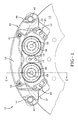
- a brake made in accordance with the present invention is indicated generally by the numeral 10 and includes a housing 11 that carries and protects the operating components of brake 10.
- Brake 10 is secured to a machine or vehicle frame by a plurality of bolts (not shown) that are inserted through holes 12 in housing 11. As shown in Fig. 1 , brake 10 is positioned over a rotor 13 for selective frictional engagement therewith.
- housing 11 includes a first housing half 14 and a second housing half 15, opposed from first housing half 14. Housing halves 14 and 15 are joined by a bridge 16 so that, in cross-section, housing 11 is generally in the shape of an inverted U. Each housing half 14 and 15 includes a pair of stepped bores 17 that are each adapted to receive a piston 18 therein. It should be appreciated that, though the present embodiment discloses two pistons 18 in each housing half, it is contemplated that each housing half may include just a single piston.
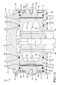
- Each stepped bore 17 includes a first circumferential surface 20 on the outward end thereof.
- First surface 20 includes a circumferential groove 21 that selectively receives a C-ring 22 therein.
- a second circumferential surface 23 extends inwardly from first circumferential surface 20.
- Second circumferential surface 23 has a smaller diameter than first circumferential surface 10, thereby forming a ledge 24 at the intersection thereof.
- Second circumferential surface 23 further includes a circumferential groove 25 that is adapted to receive a seal 26.
- seal 26 may be annular, with a square cross-section.
- a disc shaped end cap 30 is provided in each bore 17 and includes an outer circumferential surface 31 having a diameter slightly smaller than the diameter of first circumferential surface 20. In this manner, end cap 30 is received in first circumferential surface 20 of bore 17 and secured between ledge 24 and C-ring 22. End cap 30 includes a circumferential groove 32 that is adapted to receive an O-ring 33 therein. End cap 30 further includes a threaded bore 28 that receives a screw 29 during normal operation. However, screw 29 may be removed during servicing, allowing a slide hammer to be inserted so that end cap 30 may be pulled out of first circumferential surface 20 of stepped bore 17. This end cap 30 is an improvement over prior designs in that it offers no leak path due to gasket failure, it reduces the possibility of plate deflection, and it saves both time and money because no fasteners are required other than the C-ring to secure end cap 30 in place.
- Each piston 18 may be generally cup shaped with a rear, disc shaped body 35 and a circumferentially extending flange 36. Pistons 18 are axially movable within bore 17 to selectively apply pressure to stator assemblies 37. Piston movement is caused by the introduction of pressurized fluid into the chamber 38 formed between end cap 30 and body 35. As is evident from Fig. 2 , O-rings 33 prevent the escape of operating fluid from between end cap 30 and first circumferential surface 20. Likewise, seals 26 prevent the escape of operating fluid from between piston 18 and second circumferential surface 23.
- Each stator assembly 37 includes a stator plate 40 with a friction material 41 bonded thereto. As shown in Fig. 2 , flange 36 of piston 18 engages the surface of stator plate 40 opposed from the friction material 41. Thus, when pressurized fluid is communicated to chambers 38, the opposed stator assemblies 37 are pushed toward each other and engage rotor 13 to cause a braking force to be applied.
- Each housing half 14 and 15 includes holes 42 on opposed ends thereof. Each pair of aligned holes 42 receive a pin 43 therein, which is retained by cotter pins 44. Likewise, each stator plate 40 includes opposed thru holes 45 that slidably receive pin 43 therein. In this manner, stator assemblies 37 are carried by pins 44 and are free to slide and transfer the piston force to rotor 13.
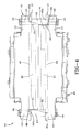
- brake 10 includes a brake fluid supply network, indicated generally by the numeral 50.
- Network 50 includes an input port 51 located at the side face of first housing half 14.
- Input port 51 is in fluid communication with a first channel 52 that extends through bridge 16 and into second housing half 15.
- a feed bore 53 extends from first channel 52 and communicates with first chamber 38a.
- a second feed bore 54 extends from first channel 52 and communicates with second chamber 38b.
- a cross channel 55 extends perpendicularly from first channel 52 longitudinally along second housing half 15 and terminates at a second channel 56.
- Second channel 56 extends through bridge 16 back to first housing half and terminates at an output port 57.
- a third feed bore 58 extends from second channel 56 and communicates with third chamber 38c.
- a fourth feed bore 59 extends from second channel 56 and communicates with fourth chamber 38d. In this manner, one input port may provide operating fluid to all pistons.
- second housing half also includes ports 60 that are in communication with first and second channels 52 and 56. Plugs 61 are secured therein to prevent fluid leakage, however, they may also be used to provide additional fluid inputs or outputs.
- a bleed plug 62 may be positioned in output port 57 and, during normal brake use, is configured to prevent any leakage of fluids therethrough. However, should the user wish to bleed entrained air from the brake, the user may configure the bleed plug to allow fluid leakage. Thereafter, brake fluid may be forced into the brake through input port 51. Consequently, any air trapped in chamber 38a will be displaced and forced along first channel 52. In a cascading fashion, air from chambers 38b, 38c and 38d will be evacuated of air, leaving only brake fluid therein. Air is evacuated through outlet port 57 until no more entrained air remains.
- the above configuration provides positive bleeding to all piston chambers from one side of the brake. Further, this forces all air to be bled from the opposing pistons before it reaches the bleed plug 62.
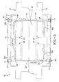
- Stator plate 40 includes ears 65a and 65b on opposed ends thereof.
- ear 65a includes a generally rounded, or continuously curved shape.
- Ear 65b is slightly larger than ear 65a and includes a flattened area 66 at the inner side surface thereof.
- bridge 16 includes recessed areas 67 on opposed ends and opposed sides of bridge 16. The recessed areas 67 are shaped such that when a stator assembly 37 is mounted on pin 43, the smaller, rounded, non-flattened ear 65a is positioned in the non-recessed area 68, while the larger, flattened ear 65b is located in the recessed area 67.
- stator assemblies 37 This requires an installer to locate the stator assemblies 37 in the proper orientation, as the flattened ear 65b is sized to interfere with the non-recessed area 68 to prevent installation if stator assemblies 37 are not in the proper orientation. In this manner, brake damage due to improper installation is prevented.
Landscapes
- Engineering & Computer Science (AREA)
- General Engineering & Computer Science (AREA)
- Mechanical Engineering (AREA)
- Braking Arrangements (AREA)
Applications Claiming Priority (2)
| Application Number | Priority Date | Filing Date | Title |
|---|---|---|---|
| US93257207P | 2007-05-31 | 2007-05-31 | |
| US12/151,287 US7597178B2 (en) | 2007-05-31 | 2008-05-06 | Caliper brake |
Publications (3)
| Publication Number | Publication Date |
|---|---|
| EP1998066A2 true EP1998066A2 (de) | 2008-12-03 |
| EP1998066A3 EP1998066A3 (de) | 2008-12-31 |
| EP1998066B1 EP1998066B1 (de) | 2010-04-21 |
Family
ID=39714109
Family Applications (1)
| Application Number | Title | Priority Date | Filing Date |
|---|---|---|---|
| EP08251834A Not-in-force EP1998066B1 (de) | 2007-05-31 | 2008-05-27 | Bremssattel |
Country Status (5)
| Country | Link |
|---|---|
| US (1) | US7597178B2 (de) |
| EP (1) | EP1998066B1 (de) |
| AT (1) | ATE465351T1 (de) |
| DE (1) | DE602008001027D1 (de) |
| DK (1) | DK1998066T3 (de) |
Cited By (5)
| Publication number | Priority date | Publication date | Assignee | Title |
|---|---|---|---|---|
| EP2088345A1 (de) * | 2008-02-07 | 2009-08-12 | Shimano, Inc. | Hydraulischer Sattel für eine Scheibenbremse |
| EP2199640A1 (de) | 2008-12-16 | 2010-06-23 | Meritor Heavy Vehicle Braking Systems (UK) Limited | Scheibenbremse |
| CN107709817A (zh) * | 2015-07-03 | 2018-02-16 | 日立汽车系统株式会社 | 盘式制动器及盘式制动器的制造方法 |
| CN111609062A (zh) * | 2020-06-04 | 2020-09-01 | 徐州徐工矿业机械有限公司 | 调整驻车制动器间隙的安装装置、驻车制动器及矿用自卸车 |
| US20230086116A1 (en) * | 2020-06-02 | 2023-03-23 | Mann+Hummel Gmbh | Brake Caliper Device, Disc Brake Assembly, Use of a Brake Caliper Device and Method for Radially Retaining Air |
Families Citing this family (9)
| Publication number | Priority date | Publication date | Assignee | Title |
|---|---|---|---|---|
| US20090200128A1 (en) * | 2008-02-07 | 2009-08-13 | Shimano Inc. | Hydraulic disc brake caliper with one way plumbing |
| US8272484B1 (en) * | 2008-05-02 | 2012-09-25 | Ausco Products, Inc. | Caliper brake |
| JP5157816B2 (ja) * | 2008-10-21 | 2013-03-06 | 株式会社アドヴィックス | ピストン対向型ディスクブレーキ |
| US20120085598A1 (en) * | 2010-10-12 | 2012-04-12 | Ausco Products, Inc. | Caliper brake |
| US20130333990A1 (en) * | 2012-06-13 | 2013-12-19 | Amsted Rail Company, Inc. | Railcar brake beam wear liner |
| US9193413B1 (en) * | 2014-06-11 | 2015-11-24 | Shimano Inc. | Bicycle disc brake caliper |
| ZA201905783B (en) | 2018-09-07 | 2020-07-29 | Ausco Prod Inc | Stator pad assembly |
| US11149807B2 (en) | 2019-06-03 | 2021-10-19 | Ausco Products, Inc. | Hydraulic caliper disc brake with spherical-faced washers |
| DE102023104601A1 (de) * | 2023-02-24 | 2024-08-29 | Shimano Inc. | Scheibenbremszange für ein muskelkraftbetriebenes fahrzeug |
Family Cites Families (13)
| Publication number | Priority date | Publication date | Assignee | Title |
|---|---|---|---|---|
| GB909251A (en) | 1958-01-18 | 1962-10-31 | Dunlop Rubber Co | Improvements in or relating to fluid pressure operated devices |
| GB915741A (en) | 1958-02-13 | 1963-01-16 | Dunlop Rubber Co | Improvements in brakes, clutches and the like |
| GB1387833A (en) * | 1971-03-19 | 1975-03-19 | Girling Ltd | Method of making calipers of pressure fluid operated disc brakes and the calipers themselves |
| US3800923A (en) * | 1972-02-14 | 1974-04-02 | Dayton Steel Foundry Co | Disc brake caliper and friction pad mounting means |
| US3862674A (en) * | 1973-04-09 | 1975-01-28 | Lambert & Brake Corp | Caliper disk brake having easily removable linings |
| DE2557700A1 (de) * | 1975-12-20 | 1977-06-30 | Kugelfischer G Schaefer & Co | Sattel fuer eine hydraulisch betaetigte scheibenbremse |
| DE3338109A1 (de) * | 1983-10-20 | 1985-05-02 | Alfred Teves Gmbh, 6000 Frankfurt | Scheibenbremse fuer fahrzeuge, insbesondere kraftfahrzeuge |
| JP3409130B2 (ja) * | 1994-05-31 | 2003-05-26 | トキコ株式会社 | ディスクブレーキ |
| JP3568752B2 (ja) * | 1997-10-03 | 2004-09-22 | 住友電気工業株式会社 | マルチポット型ディスクブレーキ |
| JPH11230205A (ja) | 1998-02-06 | 1999-08-27 | Akebono Brake Ind Co Ltd | オポーズド型ディスクブレーキキャリパ |
| JP2002333043A (ja) | 2001-05-10 | 2002-11-22 | Sumitomo Denko Brake Systems Kk | ディスクブレーキ |
| WO2004011819A1 (en) | 2002-07-30 | 2004-02-05 | Freni Brembo S.P.A. | Caliper for a disc brake |
| DE102004001495A1 (de) * | 2004-01-09 | 2005-08-11 | Gustav Magenwirth Gmbh & Co. Kg | Bremszange und Verfahren zur Herstellung eines Gehäuses einer Bremszange |
-
2008
- 2008-05-06 US US12/151,287 patent/US7597178B2/en active Active
- 2008-05-27 EP EP08251834A patent/EP1998066B1/de not_active Not-in-force
- 2008-05-27 DE DE602008001027T patent/DE602008001027D1/de not_active Expired - Fee Related
- 2008-05-27 AT AT08251834T patent/ATE465351T1/de not_active IP Right Cessation
- 2008-05-27 DK DK08251834.1T patent/DK1998066T3/da active
Cited By (9)
| Publication number | Priority date | Publication date | Assignee | Title |
|---|---|---|---|---|
| EP2088345A1 (de) * | 2008-02-07 | 2009-08-12 | Shimano, Inc. | Hydraulischer Sattel für eine Scheibenbremse |
| US8365878B2 (en) | 2008-02-07 | 2013-02-05 | Shimano Inc. | Hydraulic disc brake caliper with one way plumbing |
| US9873479B2 (en) | 2008-02-07 | 2018-01-23 | Shimano Inc. | Hydraulic disc brake caliper with one way plumbing |
| EP2199640A1 (de) | 2008-12-16 | 2010-06-23 | Meritor Heavy Vehicle Braking Systems (UK) Limited | Scheibenbremse |
| US7926631B2 (en) | 2008-12-16 | 2011-04-19 | Mentor Heavy Vehicle Braking Systems (UK) Limited | Disc brake |
| CN107709817A (zh) * | 2015-07-03 | 2018-02-16 | 日立汽车系统株式会社 | 盘式制动器及盘式制动器的制造方法 |
| US20230086116A1 (en) * | 2020-06-02 | 2023-03-23 | Mann+Hummel Gmbh | Brake Caliper Device, Disc Brake Assembly, Use of a Brake Caliper Device and Method for Radially Retaining Air |
| CN111609062A (zh) * | 2020-06-04 | 2020-09-01 | 徐州徐工矿业机械有限公司 | 调整驻车制动器间隙的安装装置、驻车制动器及矿用自卸车 |
| CN111609062B (zh) * | 2020-06-04 | 2021-09-14 | 徐州徐工矿业机械有限公司 | 调整驻车制动器间隙的安装装置、驻车制动器及矿用自卸车 |
Also Published As
| Publication number | Publication date |
|---|---|
| EP1998066A3 (de) | 2008-12-31 |
| DK1998066T3 (da) | 2010-08-02 |
| US7597178B2 (en) | 2009-10-06 |
| US20080296103A1 (en) | 2008-12-04 |
| ATE465351T1 (de) | 2010-05-15 |
| EP1998066B1 (de) | 2010-04-21 |
| DE602008001027D1 (de) | 2010-06-02 |
Similar Documents
| Publication | Publication Date | Title |
|---|---|---|
| EP1998066B1 (de) | Bremssattel | |
| CN102758974B (zh) | 液压制动器软管结构 | |
| US7634993B2 (en) | Gas manifold for a cooking range with an emergency tap | |
| US7909147B1 (en) | Low drag failsafe brake | |
| US8784083B2 (en) | Pump having a flow guide device between at least one pressure plate and a housing | |
| US8733515B2 (en) | Caliper body for disc brake for vehicle | |
| CN106907542B (zh) | 阳或阴快速联接元件以及包括这种元件的快速联接器 | |
| US7140481B2 (en) | Clutch piston amplifier assembly | |
| US9637100B2 (en) | Hydraulic unit for a slip control system of a hydraulic vehicle brake system | |
| US5711151A (en) | Brake-pressure modulation device | |
| US8272484B1 (en) | Caliper brake | |
| US11603161B2 (en) | Bicycle caliper | |
| CN106163891A (zh) | 液压设备 | |
| EP3309028B1 (de) | Entlüftungsventil für ein hydraulisches fahrradbremssystem | |
| US5279124A (en) | Cartridge for a master cylinder assembly for a fluid pressure control system and method for installing a master cylinder assembly in a fluid pressure control system | |
| US20110232370A1 (en) | Test port adapter for ep overlay | |
| US4516470A (en) | Unbalanced hydraulic amplifier valve assembly | |
| KR100300271B1 (ko) | 클러치배력장치 | |
| EP1175321B1 (de) | Axial-bremsproportionierkugelventil | |
| CN110081256B (zh) | 液压法兰 | |
| CN111022400B (zh) | 方便泄压的液压双向锁 | |
| EP3738847B1 (de) | Federbremsaktuator für ein fahrzeug, insbesondere ein nutzfahrzeug | |
| US20250313182A1 (en) | Primary gasket for a cylinder assembly, cylinder assembly | |
| TWI661968B (zh) | 自行車液壓組件 | |
| EP4522468B1 (de) | Primärdichtung für eine zylindereinheit, zylindereinheit |
Legal Events
| Date | Code | Title | Description |
|---|---|---|---|
| PUAI | Public reference made under article 153(3) epc to a published international application that has entered the european phase |
Free format text: ORIGINAL CODE: 0009012 |
|
| PUAL | Search report despatched |
Free format text: ORIGINAL CODE: 0009013 |
|
| AK | Designated contracting states |
Kind code of ref document: A2 Designated state(s): AT BE BG CH CY CZ DE DK EE ES FI FR GB GR HR HU IE IS IT LI LT LU LV MC MT NL NO PL PT RO SE SI SK TR |
|
| AX | Request for extension of the european patent |
Extension state: AL BA MK RS |
|
| AK | Designated contracting states |
Kind code of ref document: A3 Designated state(s): AT BE BG CH CY CZ DE DK EE ES FI FR GB GR HR HU IE IS IT LI LT LU LV MC MT NL NO PL PT RO SE SI SK TR |
|
| AX | Request for extension of the european patent |
Extension state: AL BA MK RS |
|
| 17P | Request for examination filed |
Effective date: 20090427 |
|
| 17Q | First examination report despatched |
Effective date: 20090615 |
|
| AKX | Designation fees paid |
Designated state(s): AT BE BG CH CY CZ DE DK EE ES FI FR GB GR HR HU IE IS IT LI LT LU LV MC MT NL NO PL PT RO SE SI SK TR |
|
| GRAP | Despatch of communication of intention to grant a patent |
Free format text: ORIGINAL CODE: EPIDOSNIGR1 |
|
| GRAS | Grant fee paid |
Free format text: ORIGINAL CODE: EPIDOSNIGR3 |
|
| GRAA | (expected) grant |
Free format text: ORIGINAL CODE: 0009210 |
|
| AK | Designated contracting states |
Kind code of ref document: B1 Designated state(s): AT BE BG CH CY CZ DE DK EE ES FI FR GB GR HR HU IE IS IT LI LT LU LV MC MT NL NO PL PT RO SE SI SK TR |
|
| REG | Reference to a national code |
Ref country code: GB Ref legal event code: FG4D |
|
| REG | Reference to a national code |
Ref country code: CH Ref legal event code: EP |
|
| REG | Reference to a national code |
Ref country code: IE Ref legal event code: FG4D |
|
| REF | Corresponds to: |
Ref document number: 602008001027 Country of ref document: DE Date of ref document: 20100602 Kind code of ref document: P |
|
| REG | Reference to a national code |
Ref country code: SE Ref legal event code: TRGR |
|
| REG | Reference to a national code |
Ref country code: DK Ref legal event code: T3 |
|
| REG | Reference to a national code |
Ref country code: NL Ref legal event code: VDEP Effective date: 20100421 |
|
| LTIE | Lt: invalidation of european patent or patent extension |
Effective date: 20100421 |
|
| PG25 | Lapsed in a contracting state [announced via postgrant information from national office to epo] |
Ref country code: ES Free format text: LAPSE BECAUSE OF FAILURE TO SUBMIT A TRANSLATION OF THE DESCRIPTION OR TO PAY THE FEE WITHIN THE PRESCRIBED TIME-LIMIT Effective date: 20100801 Ref country code: NO Free format text: LAPSE BECAUSE OF FAILURE TO SUBMIT A TRANSLATION OF THE DESCRIPTION OR TO PAY THE FEE WITHIN THE PRESCRIBED TIME-LIMIT Effective date: 20100721 Ref country code: NL Free format text: LAPSE BECAUSE OF FAILURE TO SUBMIT A TRANSLATION OF THE DESCRIPTION OR TO PAY THE FEE WITHIN THE PRESCRIBED TIME-LIMIT Effective date: 20100421 Ref country code: LT Free format text: LAPSE BECAUSE OF FAILURE TO SUBMIT A TRANSLATION OF THE DESCRIPTION OR TO PAY THE FEE WITHIN THE PRESCRIBED TIME-LIMIT Effective date: 20100421 |
|
| PG25 | Lapsed in a contracting state [announced via postgrant information from national office to epo] |
Ref country code: SI Free format text: LAPSE BECAUSE OF FAILURE TO SUBMIT A TRANSLATION OF THE DESCRIPTION OR TO PAY THE FEE WITHIN THE PRESCRIBED TIME-LIMIT Effective date: 20100421 Ref country code: IS Free format text: LAPSE BECAUSE OF FAILURE TO SUBMIT A TRANSLATION OF THE DESCRIPTION OR TO PAY THE FEE WITHIN THE PRESCRIBED TIME-LIMIT Effective date: 20100821 Ref country code: FI Free format text: LAPSE BECAUSE OF FAILURE TO SUBMIT A TRANSLATION OF THE DESCRIPTION OR TO PAY THE FEE WITHIN THE PRESCRIBED TIME-LIMIT Effective date: 20100421 Ref country code: AT Free format text: LAPSE BECAUSE OF FAILURE TO SUBMIT A TRANSLATION OF THE DESCRIPTION OR TO PAY THE FEE WITHIN THE PRESCRIBED TIME-LIMIT Effective date: 20100421 Ref country code: LV Free format text: LAPSE BECAUSE OF FAILURE TO SUBMIT A TRANSLATION OF THE DESCRIPTION OR TO PAY THE FEE WITHIN THE PRESCRIBED TIME-LIMIT Effective date: 20100421 Ref country code: HR Free format text: LAPSE BECAUSE OF FAILURE TO SUBMIT A TRANSLATION OF THE DESCRIPTION OR TO PAY THE FEE WITHIN THE PRESCRIBED TIME-LIMIT Effective date: 20100421 |
|
| PG25 | Lapsed in a contracting state [announced via postgrant information from national office to epo] |
Ref country code: MC Free format text: LAPSE BECAUSE OF NON-PAYMENT OF DUE FEES Effective date: 20100531 Ref country code: PL Free format text: LAPSE BECAUSE OF FAILURE TO SUBMIT A TRANSLATION OF THE DESCRIPTION OR TO PAY THE FEE WITHIN THE PRESCRIBED TIME-LIMIT Effective date: 20100421 Ref country code: CY Free format text: LAPSE BECAUSE OF FAILURE TO SUBMIT A TRANSLATION OF THE DESCRIPTION OR TO PAY THE FEE WITHIN THE PRESCRIBED TIME-LIMIT Effective date: 20100602 |
|
| PG25 | Lapsed in a contracting state [announced via postgrant information from national office to epo] |
Ref country code: EE Free format text: LAPSE BECAUSE OF FAILURE TO SUBMIT A TRANSLATION OF THE DESCRIPTION OR TO PAY THE FEE WITHIN THE PRESCRIBED TIME-LIMIT Effective date: 20100421 |
|
| PLBE | No opposition filed within time limit |
Free format text: ORIGINAL CODE: 0009261 |
|
| STAA | Information on the status of an ep patent application or granted ep patent |
Free format text: STATUS: NO OPPOSITION FILED WITHIN TIME LIMIT |
|
| PG25 | Lapsed in a contracting state [announced via postgrant information from national office to epo] |
Ref country code: SK Free format text: LAPSE BECAUSE OF FAILURE TO SUBMIT A TRANSLATION OF THE DESCRIPTION OR TO PAY THE FEE WITHIN THE PRESCRIBED TIME-LIMIT Effective date: 20100421 Ref country code: CZ Free format text: LAPSE BECAUSE OF FAILURE TO SUBMIT A TRANSLATION OF THE DESCRIPTION OR TO PAY THE FEE WITHIN THE PRESCRIBED TIME-LIMIT Effective date: 20100421 Ref country code: RO Free format text: LAPSE BECAUSE OF FAILURE TO SUBMIT A TRANSLATION OF THE DESCRIPTION OR TO PAY THE FEE WITHIN THE PRESCRIBED TIME-LIMIT Effective date: 20100421 Ref country code: BE Free format text: LAPSE BECAUSE OF FAILURE TO SUBMIT A TRANSLATION OF THE DESCRIPTION OR TO PAY THE FEE WITHIN THE PRESCRIBED TIME-LIMIT Effective date: 20100421 |
|
| 26N | No opposition filed |
Effective date: 20110124 |
|
| PG25 | Lapsed in a contracting state [announced via postgrant information from national office to epo] |
Ref country code: DE Free format text: LAPSE BECAUSE OF NON-PAYMENT OF DUE FEES Effective date: 20101201 Ref country code: MT Free format text: LAPSE BECAUSE OF FAILURE TO SUBMIT A TRANSLATION OF THE DESCRIPTION OR TO PAY THE FEE WITHIN THE PRESCRIBED TIME-LIMIT Effective date: 20100421 Ref country code: IE Free format text: LAPSE BECAUSE OF NON-PAYMENT OF DUE FEES Effective date: 20100527 |
|
| PG25 | Lapsed in a contracting state [announced via postgrant information from national office to epo] |
Ref country code: GR Free format text: LAPSE BECAUSE OF FAILURE TO SUBMIT A TRANSLATION OF THE DESCRIPTION OR TO PAY THE FEE WITHIN THE PRESCRIBED TIME-LIMIT Effective date: 20100722 |
|
| PG25 | Lapsed in a contracting state [announced via postgrant information from national office to epo] |
Ref country code: FR Free format text: LAPSE BECAUSE OF NON-PAYMENT OF DUE FEES Effective date: 20100621 |
|
| PG25 | Lapsed in a contracting state [announced via postgrant information from national office to epo] |
Ref country code: LU Free format text: LAPSE BECAUSE OF NON-PAYMENT OF DUE FEES Effective date: 20100527 Ref country code: PT Free format text: LAPSE BECAUSE OF FAILURE TO SUBMIT A TRANSLATION OF THE DESCRIPTION OR TO PAY THE FEE WITHIN THE PRESCRIBED TIME-LIMIT Effective date: 20100921 Ref country code: BG Free format text: LAPSE BECAUSE OF FAILURE TO SUBMIT A TRANSLATION OF THE DESCRIPTION OR TO PAY THE FEE WITHIN THE PRESCRIBED TIME-LIMIT Effective date: 20100421 Ref country code: HU Free format text: LAPSE BECAUSE OF FAILURE TO SUBMIT A TRANSLATION OF THE DESCRIPTION OR TO PAY THE FEE WITHIN THE PRESCRIBED TIME-LIMIT Effective date: 20101022 |
|
| PG25 | Lapsed in a contracting state [announced via postgrant information from national office to epo] |
Ref country code: TR Free format text: LAPSE BECAUSE OF FAILURE TO SUBMIT A TRANSLATION OF THE DESCRIPTION OR TO PAY THE FEE WITHIN THE PRESCRIBED TIME-LIMIT Effective date: 20100421 |
|
| REG | Reference to a national code |
Ref country code: CH Ref legal event code: PL |
|
| PG25 | Lapsed in a contracting state [announced via postgrant information from national office to epo] |
Ref country code: LI Free format text: LAPSE BECAUSE OF NON-PAYMENT OF DUE FEES Effective date: 20120531 Ref country code: CH Free format text: LAPSE BECAUSE OF NON-PAYMENT OF DUE FEES Effective date: 20120531 |
|
| PG25 | Lapsed in a contracting state [announced via postgrant information from national office to epo] |
Ref country code: BG Free format text: LAPSE BECAUSE OF FAILURE TO SUBMIT A TRANSLATION OF THE DESCRIPTION OR TO PAY THE FEE WITHIN THE PRESCRIBED TIME-LIMIT Effective date: 20100721 |
|
| PGFP | Annual fee paid to national office [announced via postgrant information from national office to epo] |
Ref country code: DK Payment date: 20200512 Year of fee payment: 13 |
|
| PGFP | Annual fee paid to national office [announced via postgrant information from national office to epo] |
Ref country code: IT Payment date: 20200414 Year of fee payment: 13 Ref country code: SE Payment date: 20200512 Year of fee payment: 13 Ref country code: GB Payment date: 20200520 Year of fee payment: 13 |
|
| REG | Reference to a national code |
Ref country code: DK Ref legal event code: EBP Effective date: 20210531 |
|
| REG | Reference to a national code |
Ref country code: SE Ref legal event code: EUG |
|
| GBPC | Gb: european patent ceased through non-payment of renewal fee |
Effective date: 20210527 |
|
| PG25 | Lapsed in a contracting state [announced via postgrant information from national office to epo] |
Ref country code: SE Free format text: LAPSE BECAUSE OF NON-PAYMENT OF DUE FEES Effective date: 20210528 |
|
| PG25 | Lapsed in a contracting state [announced via postgrant information from national office to epo] |
Ref country code: GB Free format text: LAPSE BECAUSE OF NON-PAYMENT OF DUE FEES Effective date: 20210527 Ref country code: DK Free format text: LAPSE BECAUSE OF NON-PAYMENT OF DUE FEES Effective date: 20210531 |
|
| PG25 | Lapsed in a contracting state [announced via postgrant information from national office to epo] |
Ref country code: IT Free format text: LAPSE BECAUSE OF NON-PAYMENT OF DUE FEES Effective date: 20200527 |
|
| PG25 | Lapsed in a contracting state [announced via postgrant information from national office to epo] |
Ref country code: IT Free format text: LAPSE BECAUSE OF NON-PAYMENT OF DUE FEES Effective date: 20210527 |