EP1998091A2 - Dispositif de commande pneumatique pour un outil de levage à air comprimé - Google Patents
Dispositif de commande pneumatique pour un outil de levage à air comprimé Download PDFInfo
- Publication number
- EP1998091A2 EP1998091A2 EP08008801A EP08008801A EP1998091A2 EP 1998091 A2 EP1998091 A2 EP 1998091A2 EP 08008801 A EP08008801 A EP 08008801A EP 08008801 A EP08008801 A EP 08008801A EP 1998091 A2 EP1998091 A2 EP 1998091A2
- Authority
- EP
- European Patent Office
- Prior art keywords
- compressed air
- throttle
- load
- throttle piston
- piston
- Prior art date
- Legal status (The legal status is an assumption and is not a legal conclusion. Google has not performed a legal analysis and makes no representation as to the accuracy of the status listed.)
- Granted
Links
Images


Classifications
-
- F—MECHANICAL ENGINEERING; LIGHTING; HEATING; WEAPONS; BLASTING
- F16—ENGINEERING ELEMENTS AND UNITS; GENERAL MEASURES FOR PRODUCING AND MAINTAINING EFFECTIVE FUNCTIONING OF MACHINES OR INSTALLATIONS; THERMAL INSULATION IN GENERAL
- F16K—VALVES; TAPS; COCKS; ACTUATING-FLOATS; DEVICES FOR VENTING OR AERATING
- F16K39/00—Devices for relieving the pressure on the sealing faces
- F16K39/02—Devices for relieving the pressure on the sealing faces for lift valves
- F16K39/022—Devices for relieving the pressure on the sealing faces for lift valves using balancing surfaces
-
- B—PERFORMING OPERATIONS; TRANSPORTING
- B66—HOISTING; LIFTING; HAULING
- B66D—CAPSTANS; WINCHES; TACKLES, e.g. PULLEY BLOCKS; HOISTS
- B66D3/00—Portable or mobile lifting or hauling appliances
- B66D3/18—Power-operated hoists
-
- F—MECHANICAL ENGINEERING; LIGHTING; HEATING; WEAPONS; BLASTING
- F15—FLUID-PRESSURE ACTUATORS; HYDRAULICS OR PNEUMATICS IN GENERAL
- F15B—SYSTEMS ACTING BY MEANS OF FLUIDS IN GENERAL; FLUID-PRESSURE ACTUATORS, e.g. SERVOMOTORS; DETAILS OF FLUID-PRESSURE SYSTEMS, NOT OTHERWISE PROVIDED FOR
- F15B13/00—Details of servomotor systems ; Valves for servomotor systems
- F15B13/02—Fluid distribution or supply devices characterised by their adaptation to the control of servomotors
- F15B13/04—Fluid distribution or supply devices characterised by their adaptation to the control of servomotors for use with a single servomotor
- F15B13/0416—Fluid distribution or supply devices characterised by their adaptation to the control of servomotors for use with a single servomotor with means or adapted for load sensing
- F15B13/0417—Load sensing elements; Internal fluid connections therefor; Anti-saturation or pressure-compensation valves
-
- F—MECHANICAL ENGINEERING; LIGHTING; HEATING; WEAPONS; BLASTING
- F16—ENGINEERING ELEMENTS AND UNITS; GENERAL MEASURES FOR PRODUCING AND MAINTAINING EFFECTIVE FUNCTIONING OF MACHINES OR INSTALLATIONS; THERMAL INSULATION IN GENERAL
- F16K—VALVES; TAPS; COCKS; ACTUATING-FLOATS; DEVICES FOR VENTING OR AERATING
- F16K11/00—Multiple-way valves, e.g. mixing valves; Pipe fittings incorporating such valves
- F16K11/10—Multiple-way valves, e.g. mixing valves; Pipe fittings incorporating such valves with two or more closure members not moving as a unit
- F16K11/20—Multiple-way valves, e.g. mixing valves; Pipe fittings incorporating such valves with two or more closure members not moving as a unit operated by separate actuating members
- F16K11/207—Multiple-way valves, e.g. mixing valves; Pipe fittings incorporating such valves with two or more closure members not moving as a unit operated by separate actuating members with two handles or actuating mechanisms at opposite sides of the housing
Definitions
- the invention relates to a pneumatic control device for a compressed air hoist, in particular a pneumatic control device for compressed air hoists, in which the forces for actuation are minimized and the control device operates in proportion to the actuation force.
- a compressed air hoist for example as a compressed air balancer, usually has a rotatable cable drum which is displaceably arranged along its axis of rotation. By turning the cable drum, a rope is unrolled or rolled up, to which the load to be held hangs. About a ball screw gear, the cable drum is connected to a gas horrbeaufschlagten piston. The ball screw mechanism converts an axial movement of the piston into a rotation and axial movement of the cable drum. With such a compressed air hoist, the attached load can be raised or lowered by compressed air supply or compressed air discharge.
- Pneumatic control devices for compressed air hoists such as so-called Druckmaschinebalancer, are known in various versions of the prior art.
- a pneumatic control device In a common embodiment of a pneumatic control device, the movements of a Druck Kunststoffhebezeugs be controlled by a direct manual actuation of valves.
- the use of proportionally operating valves has proved to be advantageous, in which the air passage depends proportionally on the operating force (see DE 101 34 972 A1 . EP 1 279 873 B1 ).
- the advantage here is that the operator can control different lifting or lowering speeds intuitively on the operating force.
- a disadvantage of this embodiment is that the actuating forces for the pneumatic control device are not constant, but depend on the pressure difference from the input to the output side. Thus, a sensitive control of a compressed air hoist by means of such a pneumatic control device is not possible under all conditions of use.
- a pneumatic control device includes the use of a 5/3-way valve.
- This 5/3-way valve is operated directly by the forces of the operator and gives depending on the operation control switching pulses.
- These control switching pulses control valves, which in turn supply the compressed air to the hoist or discharge compressed air from the hoist.
- the advantage of this embodiment is that the required operating force is independent of the pressure conditions in the compressed air hoist.
- a disadvantage of this embodiment is that the pneumatic control device is not working in proportion to the operating force.
- a particular disadvantage is that thereby no sensitive control of Druckmaschinehebezeugs is possible.
- the invention is therefore based on the object to improve the handling and operability of a pneumatic control device for a compressed air hoist.
- the pneumatic control device for the Druck Kunststoffhebstzeug at least one switchable valve assembly for controlling various operating conditions of the hoist, at least one connection to a compressed air source, at least one pressurizable load connection to a lifting cylinder or the like, at least one throttle device for actuating proportional pressure loading of the load port and at least one manually operable actuating member for realizing various switching states of the valve arrangement, wherein the actuating member mechanically cooperates with the throttle device, wherein the throttle device comprises at least one adjustable throttle piston, which is christvorbeetzt in two possible actuating directions includes.
- the pneumatic control device controls at least the operating conditions compressed air supply to the compressed air hoist, holding the compressed air in the compressed air hoist and compressed air discharge from the compressed air hoist.
- the supported operating states depend on the switchable valve arrangement used.
- a 3/3-way valve is provided as a switchable valve arrangement that comprises a first and a second throttle piston as a switchable valve body.
- switchable in the sense of The invention also includes so-called proportional valves, which do not allow discrete switching positions in the true sense.
- the throttle piston can be mounted, for example, axially displaceable and spring-loaded in a valve housing of the valve assembly.
- the cross-section of the throttling piston decreases in each case in the axial direction, so that the cross-section of a throttle channel closable by the relevant throttle piston increases proportionally to the axial movement of the throttle channel, the cross section of the throttle channel being maximal at maximum axial deflection of the respective throttle piston.
- the cross-sectional geometry of the throttle piston is chosen so that the overflow cross section of the throttle channels progressively increases during displacement of the throttle piston from an initial position to an end position.
- the throttling pistons each have pneumatically effective control surfaces, wherein the operating pressure of the associated compressed air line acts on the control surfaces.
- the throttle piston is achieved with the prevailing operating pressure in the respective line by a relatively simple manner.
- To operate the respective throttle piston depending on the size of the hydraulically effective control surface, only a relatively small operating force has to be applied.
- the spring force of the spring acting on the throttle piston and the bearing friction and the static friction of the seals are overcome.
- the operating forces for example, the up and down movement of a load by means of a hoist are kept low and above all in the same at different pressures.
- the first throttle piston closes in a non-actuated blocking position a compressed air supply to the load port whereas the second throttle piston closes a compressed air outlet to the atmosphere in a non-actuated blocking position.
- the pressure pre-application is different for both actuating devices of the valve arrangement.
- the pneumatically effective control surface of the first throttle piston is smaller than that of the second throttle piston.
- valve housing comprises two pilot chambers, which are connected via pressure equalization channels to the load-side compressed air line, so that in each case the secondary side, load-dependent operating pressure is applied in the pilot chambers.
- a controllable pressure regulator is preferably provided which limits the pressure applied to the compressed air connection in dependence on the pressure applied to the load connection.
- this is a control input of the pressure regulator connected to the load terminal of the valve assembly, such that a load-side pressure increase causes a corresponding increase in the working pressure of the compressed air source by a previously set to the pressure regulator value, as long as the load no longer increases.
- actuating member relative to the valve assembly movable and in the direction of gravity of the load to be lifted extending handle is provided, which acts depending on the position with respect to the valve assembly on one or the other throttle piston.
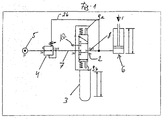
- pneumatic control device 1 comprises a valve assembly 2, a mechanical handle 3 and a controllable pressure regulator 4.
- the control device 1 is on the one hand connected to a compressed air source 5, on the other hand to a Druckensteinhebezeug 6.
- the Drucklufthebezeug 6 is in FIG. 1 schematically designed as a piston / cylinder arrangement which can be acted upon by the compressed air source 5 with pressure, such that the lifting and lowering of a posted on the compressed air hoist 6 load is possible.
- Valve arrangement 2 illustrated as a circuit diagram is designed as a 3/3-way valve and comprises a compressed air connection 7 and a load connection 8.
- the handle 3 designed as an inline handle acts as an actuating element directly mechanically on the spring-loaded switching element 9a, b of the valve arrangement 2.
- the load port 8 is separated from the compressed air source 5, so that a posted on the compressed air hoist 6 load is maintained.
- An actuation of the spring-loaded switching elements 9a, b causes a lifting or lowering of the load.
- the actuation of the first switching element 9a causes a lowering of the load; the load port 8 is released to a compressed air outlet 10 to the atmosphere.
- the handle 3 and the valve assembly 2 are movable relative to each other, wherein the valve assembly 2 is preferably fixedly mounted and the handle 3 is movable for this purpose.
- the handle 3 extends substantially in the direction of gravity of the load applied to the compressed air hoist 6, so that movement of the handle 3 against the direction of gravity causes lifting of the load and actuation of the handle 3 in the direction of gravity causes the load to be lowered.
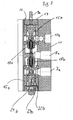
- the valve assembly 2 will be described below with reference to FIGS Figures 2-4 explained.
- the valve arrangement 2 comprises a valve housing, on which connection bores 7a, 8a and 10a are provided, wherein the connection bore 7a is provided as compressed air connection, the connection bore 8a as load connection and the connection bore 10a as compressed air outlet.
- the valve housing 11 further comprises two valve inserts, 12a, 12b, in each of which a throttling piston 13a, 13b acting as a valve body is inserted.
- the throttle piston 13a is referred to as the first throttle piston
- the throttle piston 13b is referred to as the second throttle piston.
- valve inserts 12a, 12b are each sealed via not shown O-ring seals in the valve housing 11. In the drawing, only provided for receiving the O-ring seals grooves 14 are shown.
- the throttle piston 13a, 13b are each mounted axially displaceably in guide bushes 15a, 15b formed by the valve inserts.
- the valve inserts 12a, 12b are each closed with lids 17, which are circumferentially sealed by also not shown O-ring seals.
- the cover 17 are also each center of extensions the throttle piston 13a, 13b passes, each forming the switching elements 9a, 9b.
- the throttle piston 13a, 13b are in turn sealed in the guide bushes 15a, 15b via not shown O-ring seals.
- the O-ring seals are received by the designated 14 designated grooves.
- the throttle pistons 13a, 13b remote from the extensions 9a, 9b are each provided with a closure body 18a, 18b, which cooperates with a valve seat 19a, 19b.
- the valve seats 19a, 19b are each formed by a diameter-stepped and tapered overflow opening 20a, 20b, which in each case form a throttle channel with the respective throttle piston 13a, 13b.
- the throttling pistons 13a, 13b are each held by the compression springs 21a, 21b in their unactuated initial position, ie, such that the closure body 18a, 18b is held in the associated valve seat 19a, 19b and closes the respective overflow opening 20a, 20b, as well as this in FIG. 2 is shown.
- the throttle pistons 13a, 13b are provided with hydraulically effective control surfaces 22a, 22b which each form a pilot control chamber 23a, 23b with the guide bushes 15a, 15b.
- the pilot chamber 23a communicates via a pressure equalization bore 24a, which partially passes axially through the throttle piston 13a, with the connection bore 8a.
- the pilot chamber 23b also communicates via a pressure equalization bore 24b with the connection bore 8a. Both in the pilot chamber 23a and in the pilot chamber 23b always the secondary-side operating pressure is applied.
- both the throttle piston 13a and the throttle piston 13b are so far relieved of pressure that their operation essentially only the static friction of the seals and the spring tension of the compression spring 21a, 12b must be overcome.
- the control surface 22a is larger than the control surface 22b
- the neutral position of the valve assembly is in FIG. 2 shown.
- the closure body 18a, 18b are held in each case via the compression springs 21a, 21b in the associated valve seat 19a, 19b.
- the primary operating pressure is present at the connection bore 7a, and the secondary-side operating pressure at the connection bore 8a is load-induced. In this switching position, the load is held.
- the connection bore 10a is depressurized.
- the throttle piston 13a of the in FIG. 2 shown position in the in FIG. 3 shown position the valve body 18a is raised from the associated valve seat 19b.
- the overflow opening 20a is released.
- both throttle piston 13a, 13b each have a cross-sectionally tapered portion 25a, 25b, each with the overflow 20a, 20b forms a throttle channel.
- the cross section of the throttle channel is dependent on the axial position of the respective throttle piston 13a, 13b.
- the outer contour of the tapered portion 25a, 25b of the respective throttle piston 13a, 13b is designed so that the cross section of the respective throttle channel changes over the path of the throttle piston 13a, 13b.
- the cross-section increases progressively with increasing travel of the throttle piston 13a, 13b, so that in the in FIG. 3 shown end position of the throttle piston 13a a maximum air flow from the compressed air port 7 is released to the load port 8.
- the geometric nature of the throttle piston 13a, 13b allows a proportional change in the air flow corresponding to the actuation path.
- the switching element 9b To discharge the load on the compressed air hoist, it is necessary to operate the switching element 9b so that the valve body 18b is lifted out of the associated valve seat 19b, as shown in FIG. 4 is shown. In this switching position, the load connection 8 is connected to the compressed air outlet; the load is lowered. As already mentioned above, is also the Throttling piston 13 b provided with a cross-sectionally tapered portion 25 b, to allow a wegproportionale control of the lowering speed of the load.
- a throttle is provided in the compressed air outlet 10a, which defines the maximum possible downward speed for the posted load.
- the hydraulically effective control surfaces 22a, 22b are dimensioned differently, namely, the effective control surface 22a is smaller than the effective control surface 22 b. This essentially serves to keep the hand forces for the up and down movement at different pressures the same.
Landscapes
- Engineering & Computer Science (AREA)
- General Engineering & Computer Science (AREA)
- Mechanical Engineering (AREA)
- Physics & Mathematics (AREA)
- Fluid Mechanics (AREA)
- Fluid-Pressure Circuits (AREA)
Applications Claiming Priority (1)
| Application Number | Priority Date | Filing Date | Title |
|---|---|---|---|
| DE102007025059.4A DE102007025059B4 (de) | 2007-05-29 | 2007-05-29 | Pneumatische Steuereinrichtung für ein Drucklufthebezeug |
Publications (3)
| Publication Number | Publication Date |
|---|---|
| EP1998091A2 true EP1998091A2 (fr) | 2008-12-03 |
| EP1998091A3 EP1998091A3 (fr) | 2009-12-16 |
| EP1998091B1 EP1998091B1 (fr) | 2019-10-30 |
Family
ID=39714195
Family Applications (1)
| Application Number | Title | Priority Date | Filing Date |
|---|---|---|---|
| EP08008801.6A Active EP1998091B1 (fr) | 2007-05-29 | 2008-05-10 | Dispositif de commande pneumatique pour un outil de levage à air comprimé |
Country Status (3)
| Country | Link |
|---|---|
| EP (1) | EP1998091B1 (fr) |
| DE (1) | DE102007025059B4 (fr) |
| ES (1) | ES2769258T3 (fr) |
Cited By (1)
| Publication number | Priority date | Publication date | Assignee | Title |
|---|---|---|---|---|
| CN107842535A (zh) * | 2017-11-27 | 2018-03-27 | 章丘市稻泽机械配件有限公司 | 一种机械式无杆气缸 |
Citations (1)
| Publication number | Priority date | Publication date | Assignee | Title |
|---|---|---|---|---|
| DE10134972A1 (de) | 2001-07-24 | 2003-02-20 | Demag Cranes & Components Gmbh | Durchlassventil für Strömungsmedium, insbesondere ein pneumatisches Drosselventil |
Family Cites Families (8)
| Publication number | Priority date | Publication date | Assignee | Title |
|---|---|---|---|---|
| US531682A (en) * | 1895-01-01 | John s | ||
| DE1234469B (de) * | 1959-09-21 | 1967-02-16 | Bendix Corp | Entlastetes Ventil |
| JPS59102794A (ja) * | 1982-12-01 | 1984-06-13 | 日本ニユ−マチツク工業株式会社 | エアホイストの制御装置 |
| JP2779336B2 (ja) * | 1995-07-12 | 1998-07-23 | 株式会社東洋空機製作所 | 巻上機 |
| DE19650379A1 (de) * | 1996-12-05 | 1998-06-18 | Suttner Gmbh & Co Kg | Ventilanordnung mit direkt betätigtem Ventilkörper |
| DE29713878U1 (de) * | 1997-08-04 | 1998-09-24 | Weh Gmbh, Verbindungstechnik, 89257 Illertissen | Schaltventil |
| KR20020091250A (ko) * | 2000-04-28 | 2002-12-05 | 히로타카 엔지니어링 엘티디. | 에어 밸런스 장치 |
| JP3691734B2 (ja) * | 2000-07-14 | 2005-09-07 | 株式会社東洋空機製作所 | エアホイスト |
-
2007
- 2007-05-29 DE DE102007025059.4A patent/DE102007025059B4/de not_active Expired - Fee Related
-
2008
- 2008-05-10 ES ES08008801T patent/ES2769258T3/es active Active
- 2008-05-10 EP EP08008801.6A patent/EP1998091B1/fr active Active
Patent Citations (2)
| Publication number | Priority date | Publication date | Assignee | Title |
|---|---|---|---|---|
| DE10134972A1 (de) | 2001-07-24 | 2003-02-20 | Demag Cranes & Components Gmbh | Durchlassventil für Strömungsmedium, insbesondere ein pneumatisches Drosselventil |
| EP1279873B1 (fr) | 2001-07-24 | 2004-11-17 | Demag Cranes & Components GmbH | Soupape |
Cited By (1)
| Publication number | Priority date | Publication date | Assignee | Title |
|---|---|---|---|---|
| CN107842535A (zh) * | 2017-11-27 | 2018-03-27 | 章丘市稻泽机械配件有限公司 | 一种机械式无杆气缸 |
Also Published As
| Publication number | Publication date |
|---|---|
| DE102007025059A1 (de) | 2008-12-24 |
| ES2769258T3 (es) | 2020-06-25 |
| DE102007025059B4 (de) | 2018-02-01 |
| EP1998091A3 (fr) | 2009-12-16 |
| EP1998091B1 (fr) | 2019-10-30 |
Similar Documents
| Publication | Publication Date | Title |
|---|---|---|
| DE19504364C2 (de) | Druckregelventil | |
| DE1456438C3 (de) | Druckmittelregelschaltung für eine mit einer Verschiebezylinderanordnung ausbalancierte Trag- und Einstellvorrichtung | |
| EP0197467A2 (fr) | Soupape de descente freinée et maintenu sans fuites. | |
| DE3709504C2 (de) | Ventileinrichtung | |
| EP0451543B1 (fr) | Système d'actionnement pour une vanne de régulation de vapeur | |
| EP1998091B1 (fr) | Dispositif de commande pneumatique pour un outil de levage à air comprimé | |
| DE4340283A1 (de) | Hydraulisches Steuerventil | |
| DE3216580A1 (de) | Lasthalte- und senkbremsventil | |
| DE3225132A1 (de) | Hydraulisches sicherheitsbremsventil | |
| EP0483585B1 (fr) | Valve d'étranglement proportionelle réglable à contre-réaction | |
| DE3204055A1 (de) | Druckbegrenzungs- oder -regelventil | |
| DE102008005829A1 (de) | Fahrzeugsitz mit einem höhenverstellbaren Sitzgestell | |
| DE69401196T2 (de) | Abblasventil für ein dampfgefäss | |
| EP0855520B2 (fr) | Agencement de soupape | |
| DE102004046976B4 (de) | Mehrwegeventil | |
| DE2314590A1 (de) | Ventilanordnung | |
| DE2833971C2 (de) | Leitungsbruchsicherungs-Vorrichtung zur Anordnung zwischen einem hydraulischen Steuergerät und wenigstens einem Arbeitszylinder | |
| DE60010641T2 (de) | Überdruckventil | |
| DE10161703B4 (de) | Entlüftungseinrichtung für einen Pneumatikantrieb | |
| DE69408746T2 (de) | Steuereinrichtung für einen Hydraulikmotor | |
| DE3224955C2 (de) | Proportionalventil | |
| DE710000C (de) | Ventilsteuerung fuer Pressen | |
| DE102009057807B4 (de) | Monostabiles Ventil mit Luftfeder | |
| DE19605173C2 (de) | Hydraulische Sicherheitsventilanordnung | |
| DE102005033577B4 (de) | Hydraulische Ventilanordnung |
Legal Events
| Date | Code | Title | Description |
|---|---|---|---|
| PUAI | Public reference made under article 153(3) epc to a published international application that has entered the european phase |
Free format text: ORIGINAL CODE: 0009012 |
|
| AK | Designated contracting states |
Kind code of ref document: A2 Designated state(s): AT BE BG CH CY CZ DE DK EE ES FI FR GB GR HR HU IE IS IT LI LT LU LV MC MT NL NO PL PT RO SE SI SK TR |
|
| AX | Request for extension of the european patent |
Extension state: AL BA MK RS |
|
| PUAL | Search report despatched |
Free format text: ORIGINAL CODE: 0009013 |
|
| AK | Designated contracting states |
Kind code of ref document: A3 Designated state(s): AT BE BG CH CY CZ DE DK EE ES FI FR GB GR HR HU IE IS IT LI LT LU LV MC MT NL NO PL PT RO SE SI SK TR |
|
| AX | Request for extension of the european patent |
Extension state: AL BA MK RS |
|
| 17P | Request for examination filed |
Effective date: 20100615 |
|
| AKX | Designation fees paid |
Designated state(s): AT BE BG CH CY CZ DE DK EE ES FI FR GB GR HR HU IE IS IT LI LT LU LV MC MT NL NO PL PT RO SE SI SK TR |
|
| 17Q | First examination report despatched |
Effective date: 20101126 |
|
| RAP1 | Party data changed (applicant data changed or rights of an application transferred) |
Owner name: KONECRANES LIFTING SYTEMS GMBH |
|
| STAA | Information on the status of an ep patent application or granted ep patent |
Free format text: STATUS: EXAMINATION IS IN PROGRESS |
|
| REG | Reference to a national code |
Ref country code: DE Ref legal event code: R079 Ref document number: 502008016928 Country of ref document: DE Free format text: PREVIOUS MAIN CLASS: F16K0011044000 Ipc: F16K0011200000 |
|
| GRAP | Despatch of communication of intention to grant a patent |
Free format text: ORIGINAL CODE: EPIDOSNIGR1 |
|
| STAA | Information on the status of an ep patent application or granted ep patent |
Free format text: STATUS: GRANT OF PATENT IS INTENDED |
|
| RIC1 | Information provided on ipc code assigned before grant |
Ipc: F16K 39/02 20060101ALI20190509BHEP Ipc: F16K 11/20 20060101AFI20190509BHEP Ipc: B66D 3/18 20060101ALI20190509BHEP Ipc: F15B 13/04 20060101ALI20190509BHEP |
|
| INTG | Intention to grant announced |
Effective date: 20190528 |
|
| GRAS | Grant fee paid |
Free format text: ORIGINAL CODE: EPIDOSNIGR3 |
|
| GRAA | (expected) grant |
Free format text: ORIGINAL CODE: 0009210 |
|
| STAA | Information on the status of an ep patent application or granted ep patent |
Free format text: STATUS: THE PATENT HAS BEEN GRANTED |
|
| AK | Designated contracting states |
Kind code of ref document: B1 Designated state(s): AT BE BG CH CY CZ DE DK EE ES FI FR GB GR HR HU IE IS IT LI LT LU LV MC MT NL NO PL PT RO SE SI SK TR |
|
| REG | Reference to a national code |
Ref country code: GB Ref legal event code: FG4D Free format text: NOT ENGLISH |
|
| REG | Reference to a national code |
Ref country code: CH Ref legal event code: EP |
|
| REG | Reference to a national code |
Ref country code: DE Ref legal event code: R096 Ref document number: 502008016928 Country of ref document: DE |
|
| REG | Reference to a national code |
Ref country code: AT Ref legal event code: REF Ref document number: 1196505 Country of ref document: AT Kind code of ref document: T Effective date: 20191115 |
|
| REG | Reference to a national code |
Ref country code: IE Ref legal event code: FG4D Free format text: LANGUAGE OF EP DOCUMENT: GERMAN |
|
| REG | Reference to a national code |
Ref country code: LT Ref legal event code: MG4D |
|
| PG25 | Lapsed in a contracting state [announced via postgrant information from national office to epo] |
Ref country code: GR Free format text: LAPSE BECAUSE OF FAILURE TO SUBMIT A TRANSLATION OF THE DESCRIPTION OR TO PAY THE FEE WITHIN THE PRESCRIBED TIME-LIMIT Effective date: 20200131 Ref country code: NO Free format text: LAPSE BECAUSE OF FAILURE TO SUBMIT A TRANSLATION OF THE DESCRIPTION OR TO PAY THE FEE WITHIN THE PRESCRIBED TIME-LIMIT Effective date: 20200130 Ref country code: LT Free format text: LAPSE BECAUSE OF FAILURE TO SUBMIT A TRANSLATION OF THE DESCRIPTION OR TO PAY THE FEE WITHIN THE PRESCRIBED TIME-LIMIT Effective date: 20191030 Ref country code: BG Free format text: LAPSE BECAUSE OF FAILURE TO SUBMIT A TRANSLATION OF THE DESCRIPTION OR TO PAY THE FEE WITHIN THE PRESCRIBED TIME-LIMIT Effective date: 20200130 Ref country code: FI Free format text: LAPSE BECAUSE OF FAILURE TO SUBMIT A TRANSLATION OF THE DESCRIPTION OR TO PAY THE FEE WITHIN THE PRESCRIBED TIME-LIMIT Effective date: 20191030 Ref country code: NL Free format text: LAPSE BECAUSE OF FAILURE TO SUBMIT A TRANSLATION OF THE DESCRIPTION OR TO PAY THE FEE WITHIN THE PRESCRIBED TIME-LIMIT Effective date: 20191030 Ref country code: LV Free format text: LAPSE BECAUSE OF FAILURE TO SUBMIT A TRANSLATION OF THE DESCRIPTION OR TO PAY THE FEE WITHIN THE PRESCRIBED TIME-LIMIT Effective date: 20191030 Ref country code: SE Free format text: LAPSE BECAUSE OF FAILURE TO SUBMIT A TRANSLATION OF THE DESCRIPTION OR TO PAY THE FEE WITHIN THE PRESCRIBED TIME-LIMIT Effective date: 20191030 Ref country code: PL Free format text: LAPSE BECAUSE OF FAILURE TO SUBMIT A TRANSLATION OF THE DESCRIPTION OR TO PAY THE FEE WITHIN THE PRESCRIBED TIME-LIMIT Effective date: 20191030 Ref country code: PT Free format text: LAPSE BECAUSE OF FAILURE TO SUBMIT A TRANSLATION OF THE DESCRIPTION OR TO PAY THE FEE WITHIN THE PRESCRIBED TIME-LIMIT Effective date: 20200302 |
|
| REG | Reference to a national code |
Ref country code: NL Ref legal event code: MP Effective date: 20191030 |
|
| PG25 | Lapsed in a contracting state [announced via postgrant information from national office to epo] |
Ref country code: IS Free format text: LAPSE BECAUSE OF FAILURE TO SUBMIT A TRANSLATION OF THE DESCRIPTION OR TO PAY THE FEE WITHIN THE PRESCRIBED TIME-LIMIT Effective date: 20200229 Ref country code: HR Free format text: LAPSE BECAUSE OF FAILURE TO SUBMIT A TRANSLATION OF THE DESCRIPTION OR TO PAY THE FEE WITHIN THE PRESCRIBED TIME-LIMIT Effective date: 20191030 |
|
| REG | Reference to a national code |
Ref country code: ES Ref legal event code: FG2A Ref document number: 2769258 Country of ref document: ES Kind code of ref document: T3 Effective date: 20200625 |
|
| PG25 | Lapsed in a contracting state [announced via postgrant information from national office to epo] |
Ref country code: DK Free format text: LAPSE BECAUSE OF FAILURE TO SUBMIT A TRANSLATION OF THE DESCRIPTION OR TO PAY THE FEE WITHIN THE PRESCRIBED TIME-LIMIT Effective date: 20191030 Ref country code: EE Free format text: LAPSE BECAUSE OF FAILURE TO SUBMIT A TRANSLATION OF THE DESCRIPTION OR TO PAY THE FEE WITHIN THE PRESCRIBED TIME-LIMIT Effective date: 20191030 Ref country code: RO Free format text: LAPSE BECAUSE OF FAILURE TO SUBMIT A TRANSLATION OF THE DESCRIPTION OR TO PAY THE FEE WITHIN THE PRESCRIBED TIME-LIMIT Effective date: 20191030 |
|
| REG | Reference to a national code |
Ref country code: DE Ref legal event code: R097 Ref document number: 502008016928 Country of ref document: DE |
|
| PG25 | Lapsed in a contracting state [announced via postgrant information from national office to epo] |
Ref country code: SK Free format text: LAPSE BECAUSE OF FAILURE TO SUBMIT A TRANSLATION OF THE DESCRIPTION OR TO PAY THE FEE WITHIN THE PRESCRIBED TIME-LIMIT Effective date: 20191030 |
|
| PLBE | No opposition filed within time limit |
Free format text: ORIGINAL CODE: 0009261 |
|
| STAA | Information on the status of an ep patent application or granted ep patent |
Free format text: STATUS: NO OPPOSITION FILED WITHIN TIME LIMIT |
|
| 26N | No opposition filed |
Effective date: 20200731 |
|
| PG25 | Lapsed in a contracting state [announced via postgrant information from national office to epo] |
Ref country code: SI Free format text: LAPSE BECAUSE OF FAILURE TO SUBMIT A TRANSLATION OF THE DESCRIPTION OR TO PAY THE FEE WITHIN THE PRESCRIBED TIME-LIMIT Effective date: 20191030 |
|
| PG25 | Lapsed in a contracting state [announced via postgrant information from national office to epo] |
Ref country code: LI Free format text: LAPSE BECAUSE OF NON-PAYMENT OF DUE FEES Effective date: 20200531 Ref country code: MC Free format text: LAPSE BECAUSE OF FAILURE TO SUBMIT A TRANSLATION OF THE DESCRIPTION OR TO PAY THE FEE WITHIN THE PRESCRIBED TIME-LIMIT Effective date: 20191030 Ref country code: CH Free format text: LAPSE BECAUSE OF NON-PAYMENT OF DUE FEES Effective date: 20200531 |
|
| REG | Reference to a national code |
Ref country code: BE Ref legal event code: MM Effective date: 20200531 |
|
| PG25 | Lapsed in a contracting state [announced via postgrant information from national office to epo] |
Ref country code: LU Free format text: LAPSE BECAUSE OF NON-PAYMENT OF DUE FEES Effective date: 20200510 |
|
| PG25 | Lapsed in a contracting state [announced via postgrant information from national office to epo] |
Ref country code: IE Free format text: LAPSE BECAUSE OF NON-PAYMENT OF DUE FEES Effective date: 20200510 |
|
| PG25 | Lapsed in a contracting state [announced via postgrant information from national office to epo] |
Ref country code: BE Free format text: LAPSE BECAUSE OF NON-PAYMENT OF DUE FEES Effective date: 20200531 |
|
| REG | Reference to a national code |
Ref country code: AT Ref legal event code: MM01 Ref document number: 1196505 Country of ref document: AT Kind code of ref document: T Effective date: 20200510 |
|
| PG25 | Lapsed in a contracting state [announced via postgrant information from national office to epo] |
Ref country code: AT Free format text: LAPSE BECAUSE OF NON-PAYMENT OF DUE FEES Effective date: 20200510 |
|
| REG | Reference to a national code |
Ref country code: DE Ref legal event code: R081 Ref document number: 502008016928 Country of ref document: DE Owner name: KONECRANES GLOBAL CORPORATION, FI Free format text: FORMER OWNER: KONECRANES LIFTING SYTEMS GMBH, 40789 MONHEIM, DE |
|
| REG | Reference to a national code |
Ref country code: ES Ref legal event code: PC2A Owner name: KONECRANES GLOBAL CORPORATION Effective date: 20220311 |
|
| REG | Reference to a national code |
Ref country code: GB Ref legal event code: 732E Free format text: REGISTERED BETWEEN 20220310 AND 20220316 |
|
| PG25 | Lapsed in a contracting state [announced via postgrant information from national office to epo] |
Ref country code: TR Free format text: LAPSE BECAUSE OF FAILURE TO SUBMIT A TRANSLATION OF THE DESCRIPTION OR TO PAY THE FEE WITHIN THE PRESCRIBED TIME-LIMIT Effective date: 20191030 Ref country code: MT Free format text: LAPSE BECAUSE OF FAILURE TO SUBMIT A TRANSLATION OF THE DESCRIPTION OR TO PAY THE FEE WITHIN THE PRESCRIBED TIME-LIMIT Effective date: 20191030 Ref country code: CY Free format text: LAPSE BECAUSE OF FAILURE TO SUBMIT A TRANSLATION OF THE DESCRIPTION OR TO PAY THE FEE WITHIN THE PRESCRIBED TIME-LIMIT Effective date: 20191030 |
|
| P01 | Opt-out of the competence of the unified patent court (upc) registered |
Effective date: 20230502 |
|
| PGFP | Annual fee paid to national office [announced via postgrant information from national office to epo] |
Ref country code: IT Payment date: 20230526 Year of fee payment: 16 Ref country code: FR Payment date: 20230525 Year of fee payment: 16 Ref country code: DE Payment date: 20230519 Year of fee payment: 16 Ref country code: CZ Payment date: 20230502 Year of fee payment: 16 |
|
| PGFP | Annual fee paid to national office [announced via postgrant information from national office to epo] |
Ref country code: GB Payment date: 20230523 Year of fee payment: 16 Ref country code: ES Payment date: 20230724 Year of fee payment: 16 |
|
| REG | Reference to a national code |
Ref country code: DE Ref legal event code: R119 Ref document number: 502008016928 Country of ref document: DE |
|
| PG25 | Lapsed in a contracting state [announced via postgrant information from national office to epo] |
Ref country code: CZ Free format text: LAPSE BECAUSE OF NON-PAYMENT OF DUE FEES Effective date: 20240510 |
|
| GBPC | Gb: european patent ceased through non-payment of renewal fee |
Effective date: 20240510 |
|
| PG25 | Lapsed in a contracting state [announced via postgrant information from national office to epo] |
Ref country code: CZ Free format text: LAPSE BECAUSE OF NON-PAYMENT OF DUE FEES Effective date: 20240510 |
|
| PG25 | Lapsed in a contracting state [announced via postgrant information from national office to epo] |
Ref country code: DE Free format text: LAPSE BECAUSE OF NON-PAYMENT OF DUE FEES Effective date: 20241203 |
|
| PG25 | Lapsed in a contracting state [announced via postgrant information from national office to epo] |
Ref country code: FR Free format text: LAPSE BECAUSE OF NON-PAYMENT OF DUE FEES Effective date: 20240531 |
|
| PG25 | Lapsed in a contracting state [announced via postgrant information from national office to epo] |
Ref country code: GB Free format text: LAPSE BECAUSE OF NON-PAYMENT OF DUE FEES Effective date: 20240510 Ref country code: IT Free format text: LAPSE BECAUSE OF NON-PAYMENT OF DUE FEES Effective date: 20240510 |
|
| REG | Reference to a national code |
Ref country code: ES Ref legal event code: FD2A Effective date: 20250627 |
|
| PG25 | Lapsed in a contracting state [announced via postgrant information from national office to epo] |
Ref country code: ES Free format text: LAPSE BECAUSE OF NON-PAYMENT OF DUE FEES Effective date: 20240511 |