EP1998098A2 - Accouplement tubulaire doté d'une soudure pouvant être chargée, durable et étanche aux substances - Google Patents
Accouplement tubulaire doté d'une soudure pouvant être chargée, durable et étanche aux substances Download PDFInfo
- Publication number
- EP1998098A2 EP1998098A2 EP08007011A EP08007011A EP1998098A2 EP 1998098 A2 EP1998098 A2 EP 1998098A2 EP 08007011 A EP08007011 A EP 08007011A EP 08007011 A EP08007011 A EP 08007011A EP 1998098 A2 EP1998098 A2 EP 1998098A2
- Authority
- EP
- European Patent Office
- Prior art keywords
- welding ring
- tube
- ribs
- sleeve
- pipe
- Prior art date
- Legal status (The legal status is an assumption and is not a legal conclusion. Google has not performed a legal analysis and makes no representation as to the accuracy of the status listed.)
- Granted
Links
- 238000003466 welding Methods 0.000 title claims abstract description 229
- 230000008878 coupling Effects 0.000 title claims abstract description 90
- 238000010168 coupling process Methods 0.000 title claims abstract description 90
- 238000005859 coupling reaction Methods 0.000 title claims abstract description 90
- 230000005923 long-lasting effect Effects 0.000 title 1
- 238000010438 heat treatment Methods 0.000 claims abstract description 34
- 238000004519 manufacturing process Methods 0.000 claims abstract description 4
- 239000000463 material Substances 0.000 claims description 74
- 229920001169 thermoplastic Polymers 0.000 claims description 45
- 239000004416 thermosoftening plastic Substances 0.000 claims description 45
- -1 polypropylene Polymers 0.000 claims description 10
- 238000003780 insertion Methods 0.000 claims description 8
- 230000037431 insertion Effects 0.000 claims description 8
- 239000004698 Polyethylene Substances 0.000 claims description 7
- 229920000573 polyethylene Polymers 0.000 claims description 6
- 239000004743 Polypropylene Substances 0.000 claims description 3
- 239000011324 bead Substances 0.000 claims description 3
- 229920001155 polypropylene Polymers 0.000 claims description 3
- 239000002184 metal Substances 0.000 claims description 2
- 229910052751 metal Inorganic materials 0.000 claims description 2
- 239000012815 thermoplastic material Substances 0.000 abstract description 10
- 239000000126 substance Substances 0.000 abstract description 2
- 230000002093 peripheral effect Effects 0.000 abstract 1
- 229920003023 plastic Polymers 0.000 description 17
- 239000004033 plastic Substances 0.000 description 17
- 244000089486 Phragmites australis subsp australis Species 0.000 description 9
- 239000002689 soil Substances 0.000 description 9
- 238000009434 installation Methods 0.000 description 8
- 238000000034 method Methods 0.000 description 8
- 230000035515 penetration Effects 0.000 description 6
- 238000003825 pressing Methods 0.000 description 6
- 230000000694 effects Effects 0.000 description 5
- 230000004927 fusion Effects 0.000 description 5
- 229920000642 polymer Polymers 0.000 description 5
- 238000005452 bending Methods 0.000 description 4
- 239000007787 solid Substances 0.000 description 4
- 241000196324 Embryophyta Species 0.000 description 3
- 229920001577 copolymer Polymers 0.000 description 3
- 239000010410 layer Substances 0.000 description 3
- 239000007788 liquid Substances 0.000 description 3
- 230000013011 mating Effects 0.000 description 3
- XLYOFNOQVPJJNP-UHFFFAOYSA-N water Substances O XLYOFNOQVPJJNP-UHFFFAOYSA-N 0.000 description 3
- RYGMFSIKBFXOCR-UHFFFAOYSA-N Copper Chemical compound [Cu] RYGMFSIKBFXOCR-UHFFFAOYSA-N 0.000 description 2
- 230000015572 biosynthetic process Effects 0.000 description 2
- 150000001875 compounds Chemical class 0.000 description 2
- 238000001816 cooling Methods 0.000 description 2
- 230000007547 defect Effects 0.000 description 2
- 238000011161 development Methods 0.000 description 2
- 230000018109 developmental process Effects 0.000 description 2
- 230000007613 environmental effect Effects 0.000 description 2
- 239000003673 groundwater Substances 0.000 description 2
- 230000001771 impaired effect Effects 0.000 description 2
- 238000005304 joining Methods 0.000 description 2
- 238000002844 melting Methods 0.000 description 2
- 230000008018 melting Effects 0.000 description 2
- 239000000203 mixture Substances 0.000 description 2
- 230000008635 plant growth Effects 0.000 description 2
- 238000003892 spreading Methods 0.000 description 2
- VGGSQFUCUMXWEO-UHFFFAOYSA-N Ethene Chemical compound C=C VGGSQFUCUMXWEO-UHFFFAOYSA-N 0.000 description 1
- 239000005977 Ethylene Substances 0.000 description 1
- 229920002292 Nylon 6 Polymers 0.000 description 1
- 229920002302 Nylon 6,6 Polymers 0.000 description 1
- 239000004952 Polyamide Substances 0.000 description 1
- 229920003182 Surlyn® Polymers 0.000 description 1
- BZHJMEDXRYGGRV-UHFFFAOYSA-N Vinyl chloride Chemical compound ClC=C BZHJMEDXRYGGRV-UHFFFAOYSA-N 0.000 description 1
- 238000005299 abrasion Methods 0.000 description 1
- DQXBYHZEEUGOBF-UHFFFAOYSA-N but-3-enoic acid;ethene Chemical compound C=C.OC(=O)CC=C DQXBYHZEEUGOBF-UHFFFAOYSA-N 0.000 description 1
- 238000005253 cladding Methods 0.000 description 1
- 229910052802 copper Inorganic materials 0.000 description 1
- 239000010949 copper Substances 0.000 description 1
- 238000005520 cutting process Methods 0.000 description 1
- 239000013013 elastic material Substances 0.000 description 1
- CJSRWTBMYVNLAU-UHFFFAOYSA-N ethenyl acetate;prop-1-ene Chemical compound CC=C.CC(=O)OC=C CJSRWTBMYVNLAU-UHFFFAOYSA-N 0.000 description 1
- 239000005038 ethylene vinyl acetate Substances 0.000 description 1
- 239000004744 fabric Substances 0.000 description 1
- 239000007789 gas Substances 0.000 description 1
- 239000003295 industrial effluent Substances 0.000 description 1
- 230000003993 interaction Effects 0.000 description 1
- 229920000554 ionomer Polymers 0.000 description 1
- 239000000155 melt Substances 0.000 description 1
- 238000005065 mining Methods 0.000 description 1
- 229920001200 poly(ethylene-vinyl acetate) Polymers 0.000 description 1
- 229920002647 polyamide Polymers 0.000 description 1
- 229920001083 polybutene Polymers 0.000 description 1
- 229920000098 polyolefin Polymers 0.000 description 1
- QQONPFPTGQHPMA-UHFFFAOYSA-N propylene Natural products CC=C QQONPFPTGQHPMA-UHFFFAOYSA-N 0.000 description 1
- 239000012260 resinous material Substances 0.000 description 1
- 238000007789 sealing Methods 0.000 description 1
- 238000004904 shortening Methods 0.000 description 1
- 239000002356 single layer Substances 0.000 description 1
- 238000007711 solidification Methods 0.000 description 1
- 230000008023 solidification Effects 0.000 description 1
- 239000000243 solution Substances 0.000 description 1
- 230000007704 transition Effects 0.000 description 1
- 238000009827 uniform distribution Methods 0.000 description 1
- 125000000391 vinyl group Chemical group [H]C([*])=C([H])[H] 0.000 description 1
- 229920002554 vinyl polymer Polymers 0.000 description 1
- 239000002351 wastewater Substances 0.000 description 1
- 239000003403 water pollutant Substances 0.000 description 1
Images


Classifications
-
- F—MECHANICAL ENGINEERING; LIGHTING; HEATING; WEAPONS; BLASTING
- F16—ENGINEERING ELEMENTS AND UNITS; GENERAL MEASURES FOR PRODUCING AND MAINTAINING EFFECTIVE FUNCTIONING OF MACHINES OR INSTALLATIONS; THERMAL INSULATION IN GENERAL
- F16L—PIPES; JOINTS OR FITTINGS FOR PIPES; SUPPORTS FOR PIPES, CABLES OR PROTECTIVE TUBING; MEANS FOR THERMAL INSULATION IN GENERAL
- F16L47/00—Connecting arrangements or other fittings specially adapted to be made of plastics or to be used with pipes made of plastics
- F16L47/02—Welded joints; Adhesive joints
- F16L47/03—Welded joints with an electrical resistance incorporated in the joint
-
- B—PERFORMING OPERATIONS; TRANSPORTING
- B29—WORKING OF PLASTICS; WORKING OF SUBSTANCES IN A PLASTIC STATE IN GENERAL
- B29C—SHAPING OR JOINING OF PLASTICS; SHAPING OF MATERIAL IN A PLASTIC STATE, NOT OTHERWISE PROVIDED FOR; AFTER-TREATMENT OF THE SHAPED PRODUCTS, e.g. REPAIRING
- B29C65/00—Joining or sealing of preformed parts, e.g. welding of plastics materials; Apparatus therefor
- B29C65/02—Joining or sealing of preformed parts, e.g. welding of plastics materials; Apparatus therefor by heating, with or without pressure
- B29C65/34—Joining or sealing of preformed parts, e.g. welding of plastics materials; Apparatus therefor by heating, with or without pressure using heated elements which remain in the joint, e.g. "verlorenes Schweisselement"
- B29C65/3404—Joining or sealing of preformed parts, e.g. welding of plastics materials; Apparatus therefor by heating, with or without pressure using heated elements which remain in the joint, e.g. "verlorenes Schweisselement" characterised by the type of heated elements which remain in the joint
- B29C65/3464—Joining or sealing of preformed parts, e.g. welding of plastics materials; Apparatus therefor by heating, with or without pressure using heated elements which remain in the joint, e.g. "verlorenes Schweisselement" characterised by the type of heated elements which remain in the joint characterised by the cross-section of said heated elements which remain in the joint or by the cross-section of their coating, e.g. being triangular
-
- B—PERFORMING OPERATIONS; TRANSPORTING
- B29—WORKING OF PLASTICS; WORKING OF SUBSTANCES IN A PLASTIC STATE IN GENERAL
- B29C—SHAPING OR JOINING OF PLASTICS; SHAPING OF MATERIAL IN A PLASTIC STATE, NOT OTHERWISE PROVIDED FOR; AFTER-TREATMENT OF THE SHAPED PRODUCTS, e.g. REPAIRING
- B29C65/00—Joining or sealing of preformed parts, e.g. welding of plastics materials; Apparatus therefor
- B29C65/02—Joining or sealing of preformed parts, e.g. welding of plastics materials; Apparatus therefor by heating, with or without pressure
- B29C65/34—Joining or sealing of preformed parts, e.g. welding of plastics materials; Apparatus therefor by heating, with or without pressure using heated elements which remain in the joint, e.g. "verlorenes Schweisselement"
- B29C65/3472—Joining or sealing of preformed parts, e.g. welding of plastics materials; Apparatus therefor by heating, with or without pressure using heated elements which remain in the joint, e.g. "verlorenes Schweisselement" characterised by the composition of the heated elements which remain in the joint
- B29C65/3476—Joining or sealing of preformed parts, e.g. welding of plastics materials; Apparatus therefor by heating, with or without pressure using heated elements which remain in the joint, e.g. "verlorenes Schweisselement" characterised by the composition of the heated elements which remain in the joint being metallic
- B29C65/348—Joining or sealing of preformed parts, e.g. welding of plastics materials; Apparatus therefor by heating, with or without pressure using heated elements which remain in the joint, e.g. "verlorenes Schweisselement" characterised by the composition of the heated elements which remain in the joint being metallic with a polymer coating
-
- B—PERFORMING OPERATIONS; TRANSPORTING
- B29—WORKING OF PLASTICS; WORKING OF SUBSTANCES IN A PLASTIC STATE IN GENERAL
- B29C—SHAPING OR JOINING OF PLASTICS; SHAPING OF MATERIAL IN A PLASTIC STATE, NOT OTHERWISE PROVIDED FOR; AFTER-TREATMENT OF THE SHAPED PRODUCTS, e.g. REPAIRING
- B29C66/00—General aspects of processes or apparatus for joining preformed parts
- B29C66/01—General aspects dealing with the joint area or with the area to be joined
- B29C66/05—Particular design of joint configurations
- B29C66/10—Particular design of joint configurations particular design of the joint cross-sections
- B29C66/13—Single flanged joints; Fin-type joints; Single hem joints; Edge joints; Interpenetrating fingered joints; Other specific particular designs of joint cross-sections not provided for in groups B29C66/11 - B29C66/12
- B29C66/131—Single flanged joints, i.e. one of the parts to be joined being rigid and flanged in the joint area
-
- B—PERFORMING OPERATIONS; TRANSPORTING
- B29—WORKING OF PLASTICS; WORKING OF SUBSTANCES IN A PLASTIC STATE IN GENERAL
- B29C—SHAPING OR JOINING OF PLASTICS; SHAPING OF MATERIAL IN A PLASTIC STATE, NOT OTHERWISE PROVIDED FOR; AFTER-TREATMENT OF THE SHAPED PRODUCTS, e.g. REPAIRING
- B29C66/00—General aspects of processes or apparatus for joining preformed parts
- B29C66/01—General aspects dealing with the joint area or with the area to be joined
- B29C66/32—Measures for keeping the burr form under control; Avoiding burr formation; Shaping the burr
- B29C66/322—Providing cavities in the joined article to collect the burr
-
- B—PERFORMING OPERATIONS; TRANSPORTING
- B29—WORKING OF PLASTICS; WORKING OF SUBSTANCES IN A PLASTIC STATE IN GENERAL
- B29C—SHAPING OR JOINING OF PLASTICS; SHAPING OF MATERIAL IN A PLASTIC STATE, NOT OTHERWISE PROVIDED FOR; AFTER-TREATMENT OF THE SHAPED PRODUCTS, e.g. REPAIRING
- B29C66/00—General aspects of processes or apparatus for joining preformed parts
- B29C66/50—General aspects of joining tubular articles; General aspects of joining long products, i.e. bars or profiled elements; General aspects of joining single elements to tubular articles, hollow articles or bars; General aspects of joining several hollow-preforms to form hollow or tubular articles
- B29C66/51—Joining tubular articles, profiled elements or bars; Joining single elements to tubular articles, hollow articles or bars; Joining several hollow-preforms to form hollow or tubular articles
- B29C66/52—Joining tubular articles, bars or profiled elements
- B29C66/522—Joining tubular articles
- B29C66/5221—Joining tubular articles for forming coaxial connections, i.e. the tubular articles to be joined forming a zero angle relative to each other
-
- B—PERFORMING OPERATIONS; TRANSPORTING
- B29—WORKING OF PLASTICS; WORKING OF SUBSTANCES IN A PLASTIC STATE IN GENERAL
- B29C—SHAPING OR JOINING OF PLASTICS; SHAPING OF MATERIAL IN A PLASTIC STATE, NOT OTHERWISE PROVIDED FOR; AFTER-TREATMENT OF THE SHAPED PRODUCTS, e.g. REPAIRING
- B29C66/00—General aspects of processes or apparatus for joining preformed parts
- B29C66/70—General aspects of processes or apparatus for joining preformed parts characterised by the composition, physical properties or the structure of the material of the parts to be joined; Joining with non-plastics material
- B29C66/72—General aspects of processes or apparatus for joining preformed parts characterised by the composition, physical properties or the structure of the material of the parts to be joined; Joining with non-plastics material characterised by the structure of the material of the parts to be joined
- B29C66/725—General aspects of processes or apparatus for joining preformed parts characterised by the composition, physical properties or the structure of the material of the parts to be joined; Joining with non-plastics material characterised by the structure of the material of the parts to be joined being hollow-walled or honeycombs
- B29C66/7252—General aspects of processes or apparatus for joining preformed parts characterised by the composition, physical properties or the structure of the material of the parts to be joined; Joining with non-plastics material characterised by the structure of the material of the parts to be joined being hollow-walled or honeycombs hollow-walled
- B29C66/72523—General aspects of processes or apparatus for joining preformed parts characterised by the composition, physical properties or the structure of the material of the parts to be joined; Joining with non-plastics material characterised by the structure of the material of the parts to be joined being hollow-walled or honeycombs hollow-walled multi-channelled or multi-tubular
-
- B—PERFORMING OPERATIONS; TRANSPORTING
- B29—WORKING OF PLASTICS; WORKING OF SUBSTANCES IN A PLASTIC STATE IN GENERAL
- B29C—SHAPING OR JOINING OF PLASTICS; SHAPING OF MATERIAL IN A PLASTIC STATE, NOT OTHERWISE PROVIDED FOR; AFTER-TREATMENT OF THE SHAPED PRODUCTS, e.g. REPAIRING
- B29C66/00—General aspects of processes or apparatus for joining preformed parts
- B29C66/70—General aspects of processes or apparatus for joining preformed parts characterised by the composition, physical properties or the structure of the material of the parts to be joined; Joining with non-plastics material
- B29C66/73—General aspects of processes or apparatus for joining preformed parts characterised by the composition, physical properties or the structure of the material of the parts to be joined; Joining with non-plastics material characterised by the intensive physical properties of the material of the parts to be joined, by the optical properties of the material of the parts to be joined, by the extensive physical properties of the parts to be joined, by the state of the material of the parts to be joined or by the material of the parts to be joined being a thermoplastic or a thermoset
- B29C66/739—General aspects of processes or apparatus for joining preformed parts characterised by the composition, physical properties or the structure of the material of the parts to be joined; Joining with non-plastics material characterised by the intensive physical properties of the material of the parts to be joined, by the optical properties of the material of the parts to be joined, by the extensive physical properties of the parts to be joined, by the state of the material of the parts to be joined or by the material of the parts to be joined being a thermoplastic or a thermoset characterised by the material of the parts to be joined being a thermoplastic or a thermoset
- B29C66/7392—General aspects of processes or apparatus for joining preformed parts characterised by the composition, physical properties or the structure of the material of the parts to be joined; Joining with non-plastics material characterised by the intensive physical properties of the material of the parts to be joined, by the optical properties of the material of the parts to be joined, by the extensive physical properties of the parts to be joined, by the state of the material of the parts to be joined or by the material of the parts to be joined being a thermoplastic or a thermoset characterised by the material of the parts to be joined being a thermoplastic or a thermoset characterised by the material of at least one of the parts being a thermoplastic
- B29C66/73921—General aspects of processes or apparatus for joining preformed parts characterised by the composition, physical properties or the structure of the material of the parts to be joined; Joining with non-plastics material characterised by the intensive physical properties of the material of the parts to be joined, by the optical properties of the material of the parts to be joined, by the extensive physical properties of the parts to be joined, by the state of the material of the parts to be joined or by the material of the parts to be joined being a thermoplastic or a thermoset characterised by the material of the parts to be joined being a thermoplastic or a thermoset characterised by the material of at least one of the parts being a thermoplastic characterised by the materials of both parts being thermoplastics
-
- F—MECHANICAL ENGINEERING; LIGHTING; HEATING; WEAPONS; BLASTING
- F16—ENGINEERING ELEMENTS AND UNITS; GENERAL MEASURES FOR PRODUCING AND MAINTAINING EFFECTIVE FUNCTIONING OF MACHINES OR INSTALLATIONS; THERMAL INSULATION IN GENERAL
- F16L—PIPES; JOINTS OR FITTINGS FOR PIPES; SUPPORTS FOR PIPES, CABLES OR PROTECTIVE TUBING; MEANS FOR THERMAL INSULATION IN GENERAL
- F16L25/00—Construction or details of pipe joints not provided for in, or of interest apart from, groups F16L13/00 - F16L23/00
- F16L25/0036—Joints for corrugated pipes
-
- F—MECHANICAL ENGINEERING; LIGHTING; HEATING; WEAPONS; BLASTING
- F16—ENGINEERING ELEMENTS AND UNITS; GENERAL MEASURES FOR PRODUCING AND MAINTAINING EFFECTIVE FUNCTIONING OF MACHINES OR INSTALLATIONS; THERMAL INSULATION IN GENERAL
- F16L—PIPES; JOINTS OR FITTINGS FOR PIPES; SUPPORTS FOR PIPES, CABLES OR PROTECTIVE TUBING; MEANS FOR THERMAL INSULATION IN GENERAL
- F16L25/00—Construction or details of pipe joints not provided for in, or of interest apart from, groups F16L13/00 - F16L23/00
- F16L25/0036—Joints for corrugated pipes
- F16L25/0063—Joints for corrugated pipes with two corrugated pipes being directly connected to each other
-
- B—PERFORMING OPERATIONS; TRANSPORTING
- B29—WORKING OF PLASTICS; WORKING OF SUBSTANCES IN A PLASTIC STATE IN GENERAL
- B29C—SHAPING OR JOINING OF PLASTICS; SHAPING OF MATERIAL IN A PLASTIC STATE, NOT OTHERWISE PROVIDED FOR; AFTER-TREATMENT OF THE SHAPED PRODUCTS, e.g. REPAIRING
- B29C65/00—Joining or sealing of preformed parts, e.g. welding of plastics materials; Apparatus therefor
- B29C65/02—Joining or sealing of preformed parts, e.g. welding of plastics materials; Apparatus therefor by heating, with or without pressure
- B29C65/34—Joining or sealing of preformed parts, e.g. welding of plastics materials; Apparatus therefor by heating, with or without pressure using heated elements which remain in the joint, e.g. "verlorenes Schweisselement"
- B29C65/3404—Joining or sealing of preformed parts, e.g. welding of plastics materials; Apparatus therefor by heating, with or without pressure using heated elements which remain in the joint, e.g. "verlorenes Schweisselement" characterised by the type of heated elements which remain in the joint
- B29C65/342—Joining or sealing of preformed parts, e.g. welding of plastics materials; Apparatus therefor by heating, with or without pressure using heated elements which remain in the joint, e.g. "verlorenes Schweisselement" characterised by the type of heated elements which remain in the joint comprising at least a single wire, e.g. in the form of a winding
-
- B—PERFORMING OPERATIONS; TRANSPORTING
- B29—WORKING OF PLASTICS; WORKING OF SUBSTANCES IN A PLASTIC STATE IN GENERAL
- B29C—SHAPING OR JOINING OF PLASTICS; SHAPING OF MATERIAL IN A PLASTIC STATE, NOT OTHERWISE PROVIDED FOR; AFTER-TREATMENT OF THE SHAPED PRODUCTS, e.g. REPAIRING
- B29C66/00—General aspects of processes or apparatus for joining preformed parts
- B29C66/70—General aspects of processes or apparatus for joining preformed parts characterised by the composition, physical properties or the structure of the material of the parts to be joined; Joining with non-plastics material
- B29C66/71—General aspects of processes or apparatus for joining preformed parts characterised by the composition, physical properties or the structure of the material of the parts to be joined; Joining with non-plastics material characterised by the composition of the plastics material of the parts to be joined
-
- B—PERFORMING OPERATIONS; TRANSPORTING
- B29—WORKING OF PLASTICS; WORKING OF SUBSTANCES IN A PLASTIC STATE IN GENERAL
- B29L—INDEXING SCHEME ASSOCIATED WITH SUBCLASS B29C, RELATING TO PARTICULAR ARTICLES
- B29L2023/00—Tubular articles
- B29L2023/18—Pleated or corrugated hoses
- B29L2023/186—Pleated or corrugated hoses having a smooth internal wall
Definitions
- the invention relates to a pipe coupling, which comprises a pipe and a sleeve, the pipe and the sleeve are made with a thermoplastic plastic-like material, the tube is inserted with its spigot end into the sleeve, the tube extending at least on the outer surface of the spigot in the circumferential direction Having ribs, between the sleeve and the inserted into the sleeve spigot end of the tube between two adjacent ribs, a welding ring is arranged, the welding ring is formed with a thermoplastic plastic-like material and means as electrical resistance heating with connecting lines, the thermoplastic plastic-like material of the welding ring with the thermoplastic material-like material of the tube and the sleeve, and a method for the production of pipe couplings with durable, resilient media-tight welding under longitudinal force.
- the ribs are greatly heated due to the heating in the conventional welding and greatly thinned in the welding area and the so-called burn-through effect of the ribs occurs.
- the fin material is heated and softened such that the ribs clearly lose their tube-stabilizing rigidity in the region of the coupling point of both tubes, and the conventional tube connection has the most so-called avoidable so-called restrained connection weakness.
- the object of the invention is to improve the joining of plastic pipes, so that with a simplified handling a constant wall thickness of the pipe ends to be welded can be maintained.
- the tube stiffness should not be affected in the connection area.
- the ready to be provided pipe coupling should be mechanically stiff and characterized by an intimate surface connection.
- the ready to be provided pipe coupling should show sufficient root resistance.
- the pipe coupling to be provided should have no so-called burn-through effect.
- ready-to-deliver pipe coupling should be able to counteract the bending and tensile forces occurring in the soil without, in contrast to the prior art, gaps and cracks in the joint occur.
- the ready-to-pipe coupling should be characterized by a short welding time for the economic installation of plastic pipes.
- the ready-to-use pipe coupling is intended to be used on conventional standardized plastic pipes, e.g. characterized by a high degree of rigid pipe geometry, a low wear-related high service life and a wide temperature range, such as Maincor UltraRib2 pipes, coupled and installed cost-effectively.
- media-tight connection is also understood to mean the termination of the pipes against penetration and / or discharge of media, such as gases, liquids, solutions of aqueous or nonaqueous composition, waste water, water or the like.
- pipes are also understood as solid wall pipes, corrugated pipes, corrugated pipes, pipes with ribs, double wall pipes, smooth walled pipes with a smooth outer surface and / or inner surface, etc., or combinations thereof.
- solid wall pipe is also understood to mean that the pipe, with or without ribs, is formed on its outer surface of its pipe wall, wherein the ribs and / or the pipe wall of the pipe on which the ribs are formed do not form any cavities, but their interior filled with the thermoplastic plastic-like material.
- Full wall pipes can also be double wall pipes.
- a ribbed tube is also understood to mean that the outer surface of the tube is corrugated or corrugated or, for example, annular strips or ribs are formed on the outer surface of the tubes, the head ends of the strips being at a smaller distance from the outer surface of the tubes can be considered the head ends of the ribs.
- the strips or ribs may be in longitudinal section of different geometry; For example, the strips may also have a configuration like the ribs.
- the one end of the first tube is pushed onto the double plug sleeve on one side thereof and / or the spigot end of the second tube is pushed onto the other end of the double plug socket.
- the double plug-in sleeve at its two ends at least two ribs, each having at least one welding ring.
- a bead is also understood to mean that the one end of a tube and / or a sleeve is annular on the inside about the center longitudinal axis of the tube or the sleeve is formed as a recess to form a groove to at least partially receive the welding ring in the groove or to guide this.
- the pipe coupling according to the invention may in the longitudinal section also be formed on the flanks of the ribs surveys, which may extend over the entire length of the ribs.
- the elevations have a shoulder facing the head of the ribs.
- against the shoulder of the survey is the welding ring.
- the shoulder extends e.g. over the entire length of the survey.
- the shoulder of the survey may be aligned in longitudinal section parallel to the outer surface of the second tube. It is also possible that the shoulder of the survey extends obliquely to the flank of the rib and encloses an angle with the edge of the rib, which is preferably smaller than 90 °.
- the shoulder of the protrusion is spaced from the outer surface of the second tube, which preferably corresponds to half the distance of the head end of the rib from the outer surface of the second tube. It is also possible that the welding ring is guided in a bead of the sleeve in order to increase the axial guidance of the same.
- flanks of the opposing ribs may be longitudinally sectioned instead of radially, at right angles to the center longitudinal axis of the tube, or V- or bevel-shaped and at an angle with the center longitudinal axis of less than 90 °, preferably 35 ° to 85 °, more preferably 35 to 75 °.
- the ribs for example, the two adjacent ribs against which the welding ring rests, with the formation of an above-mentioned angular, circumferentially extending cavity configured with a quarter-circular longitudinal section in the longitudinal section, against which the welding ring is applied.
- the first tube with its sleeve and / or the second tube with its sleeve are integrally formed or at least one end in a double plug socket on or pushed onto such.
- At least the inside of the sleeve is smooth-walled or smooth surface to allow a sufficient mating surface permanent and media-tight welding with the material of the weld ring.
- the welding of the inside as a mating surface of the sleeve with welding ring and ribs of the tube is so flawless that no welds of different thickness occur and their welds do not deform after cooling in contrast to the prior art.
- the welding ring contains a thermoplastic material and a device as electrical resistance heating.
- the welding ring comprises an outer shell with the thermoplastic plastic-like material, which preferably coincides with the plastic-like material of the second tube, the first tube and / or the sleeve, such as the double socket, in composition, physical and / or thermal properties.
- the plastic-like material of the welding ring with the thermoplastic plastic-like material of the first tube, the second tube and / or the sleeve, such as double socket match.
- On the inside of the outer jacket for example, lies on the intermediate jacket, which receives the device as electrical resistance heating.
- At least a part of the welding ring may protrude beyond the top end of adjacent fins, e.g. forming an annular compensation space between the trough of adjacent ribs and the welding ring.
- the homogeneous welding is intimate, so that the first tube, the second tube with the sleeve and the welding ring are quasi one piece fused, the ribs do not thin as a result of heating and the so-called burn-through effect can not occur in the ribs.
- the intimate fusion or welding of sleeve and pipe prevents the ingress of dirt.
- the uniform, uniform fusion does not result in any localized insufficient fusion defects, so that the penetration of plant roots is effectively prevented.
- the welding ring additionally contains an inner jacket with thermoplastic plastic-like material, which rests against the inside of the intermediate jacket
- the liquefaction of the plastic-like material of the outer jacket is supported by liquefaction of the thermoplastic plastic-like material of the inner shell when heated to welding temperature , so that a permanent welding of the sleeve, the first tube with the second tube in the circumferential direction occurs.
- the fin material is heated and welded to the welding ring and the first pipe or sleeve, wherein the ribs maintain their pipe-stabilizing stiffness in the region of the coupling points or welding points and have no restrained connection weakness. Due to the longitudinally positive permanent connection of the pipe coupling according to the invention arise even when occurring in the underground caused tensile forces no gaps and cracks in the weld, so that the compound is characterized by permanent media tightness.
- the welding ring may be formed in one layer with the device as electrical resistance heating.
- the multi-layer welding ring is particularly advantageous, which preferably has an outer shell and an inner shell with the thermoplastic plastic-like material and an intermediate shell arranged between the outer shell and the inner jacket with the device as electrical resistance heating and a shell thickness D2 of the inner shell has, for example greater than the shell thickness D 1 of the outer shell, in order to maintain the tightness of the connection of both tubes, even if occur as a result of subsidence on the tensile and shear forces.
- the jacket thickness D1 of the outer jacket can correspond to the wall thickness D3 of the ribs.
- the outer diameter A, for example of the outer shell, of the welding ring is greater than the average distance A1 of the opposing radially extending flanks of the adjacent ribs and at least a part of the welding ring over the top end of the ribs protrudes as excess, preferably with formation an annular compensation space after pushing the welding ring on the spigot end of the second tube or on the one end of the first tube.
- the distance between the flanks of the opposing, receiving the welding ring or the ribs defining the position of the welding ring can be understood halfway up the distance X.
- the welding ring may have in its interior a cavity which may extend continuously or discontinuously in the longitudinal direction of the strand of the welding ring.
- the sleeve facing portions of the two opposite edges of the ribs of the thermoplastic material of the welding ring with the fused the mating surfaces of the pipe and sleeve so that through the Welding homogenizing homogeneous compound of the plastic-like materials and materials is characterized as an extremely durable restrained and contrary to the ground, for example by subsidence, occurring bending and tensile forces can counteract without gaps and cracks can occur in the joint.
- the plastic-like material of the tubes and / or the plastic-like material of the welding ring can be, for example, at least one representative of the polypropylene, polyethylene, derivatives of which group.
- the thermoplastic plastic-like material of the first tube and / or the second tube and / or the plastic-like material of the welding ring may also be conventional suitable thermoplastics, for example particularly suitable polymeric materials such as olefinically unsaturated polymers and copolymers such as polyolefins such as polyethylene, polypropylene and polybutene , Ethylene and propylene copolymers, for example ethylene vinyl acetate polymers and propylene vinyl acetate polymers, halogenated vinyl polymers such as vinyl chloride polymers and copolymers, polyamides such as nylon 6 and nylon 66, and ionomer polymers such as Surlyn.
- the chosen degree of polyethylene i. high density, medium density, low density or linear low density, depends on the particular application. Suitable grades of polyethylene include, for example, Statol 930 (natural), Neste NCPE 2600 (natural) and Neste NCPE 2467 BL and NCPE 2418. Any suitable equivalent level of polyethylene can also be used.
- the thermoplastic plastic-like material of the first tube and / or the second tube and / or the plastic-like material of the welding ring can also be conventional suitable thermoplastic materials, which are e.g. from a plastic rubber-like in a rubbery or inelastic state can go after welding;
- the welding in the pipe coupling according to the invention can not affect the pipe stiffness by uniform and uniform heating of the weld ring; a sufficient elasticity of the welds, depending on the used Plastic material or material with respect to radially acting impact forces does not lead to leaks in the welds. Rather, the pipe coupling according to the invention remains permanently sealed against external inwardly pressing groundwaters, from inside to outside oppressive high pressure rinses, and chemically reactive industrial effluents with long service life and heavy use.
- the welding ring abuts against the upper regions of the adjacent opposite flanks of the ribs to form a compensation space, this is hermetically sealed by fusing the ribs without burning them with the welding ring; the material may optionally be pressed against the inner side of the sleeve opposite the compensation chamber and the desired pipe rigidity of the connection of the pipe coupling according to the invention is not impaired by the extensive intimate welding.
- the elastic concern of the welding ring both against the inside of the sleeve of the first tube and against the flanks of the two adjacent ribs supports the homogeneous surface fusion of the thermoplastic plastic-like material of the Welding ring with the thermoplastic plastic-like material of the pipes when applying the welding ring and its device as electrical resistance heating with electric current, so that when heated to welding temperature, the sleeve with the spigot end of the second tube is intimately and mechanically firmly connected.
- the welding ring can form fit against the edges of bez. create its position laterally limiting ribs, for example, with its part facing the trough.
- the pressing forces of the welding ring against the inside of the sleeve as well as against the adjacent ribs of the second tube cause a desired continuous circumferential welding to the ribs and the tube wall.
- the pipe coupling according to the invention is characterized by a continuous adjustability of the pipe lengths in place when installed in the soil, so that a cumbersome alignment of the tubes to each other and measuring advantageously unnecessary, but it is only the length limitation of the tube to be inserted and the insertion of the tube into the sleeve of the first tube and applying an electric current to the plastic melt requires.
- the pipe coupling according to the invention is suitable for a cost-effective and thus economical installation of plastic pipes, because the dimensioning and welding can take place on site and the use of residual lengths is made possible.
- the pipe coupling according to the invention makes laying with laying cushions, such as Maincor laying cushions, for example due to standardization of the pipe dimensions possible also provide a further protection of the pipe coupling according to the invention against mechanical damage, as they may occur in earthworks to provide.
- the pipe coupling according to the invention can be coupled to Maincor UltraRib2 pipes as standardized pipes, which are characterized by a high degree of rigid pipe geometry, due to low abrasion-related high service life and a wide temperature range, and laid inexpensively.
- the pipe coupling according to the invention requires only a short welding time, because due to the special structure of the weld ring and its optimal interaction with sleeve and pipe during welding.
- the short welding time also shortens installation time and reduces operating costs, such as personnel and energy costs, operating resources.
- the pipe coupling according to the invention can be used independently of the soil conditions, so that damp, cohesive soils, steep slopes, areas with high traffic loads or subsidence areas do not limit the applications of the pipe coupling according to the invention.
- the pipe coupling according to the invention can be used equally well in water abstraction areas as well as for industrial use, eg for the discharge of groundwater polluting substances, with long service life.
- connection of the tubes with the sleeve is intimately, quasi one piece, and permanently restrained by the welding.
- the pipe coupling according to the invention is so tight even with respect to pressures that by means of Hochbuch Stammmaschine the pipe coupling according to the invention can be traveled without leaks are observed.
- the welding ring abuts against the upper regions of the adjacent opposite flanks of the ribs to form a compensation space, this is hermetically sealed by fusing the ribs without burning them with the welding ring; the material may optionally be pressed against the inner side of the sleeve opposite the compensation chamber and the desired pipe rigidity of the connection of the pipe coupling according to the invention may be impaired by the extensive intimate welding.
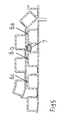
- the pipe coupling according to the invention comprises at least one pipe 1, 2, e.g. as a ribbed pipe, and a sleeve 3.
- the pipe coupling according to the invention comprises a second pipe 2 and a sleeve 3, which are connected to each other with the aid of the welding ring 7 media-tight.
- the sleeve 3 is to be formed as an end of a first tube 1, wherein the one end of the first tube 1 widens to the sleeve 3 ( Fig. 1 ).
- the sleeve 3 serves to receive the one end 4, here called spigot 4, the second tube 2.
- At least the inside 8 of the sleeve 3 of the first tube 1 is smooth-walled or smooth surface.
- the inner diameter or the clear width of the sleeve is greater than the outer diameter of the circumferential head ends 12 of the ribs 6 of the inserted spigot end of the second tube 2 in order to avoid tilting during insertion.
- the ribs 6 are hollow body-shaped to form a substantially quadrangular cavity 20.
- the ribs 6 extend in the circumferential direction and are equal to a distance A1 spaced apart.
- the ribs 6 are arranged annularly around the center longitudinal axis of the first tube 1 and the sleeve 3.
- the elastic abutment of the welding ring against the flanks 10 of the ribs 6 also prevents it from rotating about the center longitudinal axis, so that the connection lines of the device 7d remain in their position in a positionally secure manner with respect to a current source.
- This elastic locking makes it easier to connect the pipe coupling according to the invention to a power source while maintaining the alignment of the connection lines.
- the welding ring 7 is arranged between the rib 6b which follows over in the insertion direction of the spigot end 4 and the following, third-closest ribs 6c ( Fig. 2 ).
- the ribs 6, 6a, 6b, 6c are configured in such a way that the welding ring 7 rests elastically against the upper regions of the opposite flanks 10 of the ribs 6 facing away from the tube wall 18 of the second tube 2, in particular elastically by residual stress of the material.
- the Federkraftbeetzschung can also caused instead of the residual stress by the arranged in the welding ring 7 elastic heating wires 7 d or additionally support the residual stress of the welding ring 7.
- the welding ring 7 has a device as electrical resistance heater 7d.
- the device as electrical resistance heater 7 d is on both sides of the encapsulated thermoplastic plastic-like material.
- Connecting lines from the device 7d to a power source are provided in the gap 31 between the inside 8 of the sleeve 3 of the first tube 1 and the top ends 12 of the ribs 6 of FIG led out the second tube 2.
- the connecting leads can be connected to a power source to heat the thermoplastic plastic-like material and bring it to the welding or melting temperature ( Fig. 3 ).
- elevations 10 are formed in the transition region between the trough 14 and the flanks.
- the elevations extend in the circumferential direction.
- the elevations are aligned in a ring around the center longitudinal axis of the second tube 2.
- Each bumps has a shoulder against which the welding ring 7 elastically abuts to limit the penetration of the heated material of the welding ring 7 into the space 30 of adjacent ribs 6 in the direction of the tube wall 18 of the second tube 2.
- the shoulders are annularly aligned about the center longitudinal axis of the second tube 2; they run in the circumferential direction and are aligned parallel to each other and to the pipe wall 18 in longitudinal section.
- At the opposite flanks 10 of two adjacent ribs 6 are opposite shoulders of the surveys.
- the outer diameter A of the weld ring 7 corresponds to the average distance A1 of the opposite flanks 10 (Fig. Fig. 3 ). In a further embodiment, the outer diameter A of the welding ring 7 is greater than the distance A1 of the opposite flanks 10 or as the average distance A1.
- the outer diameter A of the welding ring 7 is greater than the extent of the circumference of the circumferentially extending annular Moreover, in another embodiment, the outer diameter A of the welding ring 7 may be greater than the extent of the circumference of the circumferentially extending annular corrugation 14 and less than the circumference of the periphery of the head end of a rib 6, particularly the ribs 6a receiving the welding ring. 6b, so that the welding ring 7 is arranged at half the height of the distance X.
- the mean distance A1 is the distance of the flanks 10 of the opposite, the welding ring 7 receiving ribs 6 understood at half the height of the distance X.
- the distance X corresponds to the distance of the head end 12 of the rib 6, 6a, 6b to the outer surface 5 of the tube wall 18 of the tube 1, 2 or to the trough 14.
- the shell thickness D1 of the outer shell 7a corresponds to the wall thickness D3 of the ribs 6, 6a, 6b.
- the shell thickness D2 of the inner shell 7c is equal to or greater than the shell thickness D1 of the outer shell 7a.
- the inner diameter J of the hollow-body-shaped ribs 6, 6a, 6b is 2 or 3 times greater than the outer diameter A of the welding ring 7.
- the plastic-like thermoplastic material of the welding ring 7 heats up to welding temperature and intimately connects with the thermoplastic plastic-like material of both the sleeve 3 and the ribs 6 of the second tube 2.
- the device as electrical resistance heating is a electric current conductive heating wire, which is arranged like a net or meandering in the welding ring in the circumferential direction in copper wire design.
- the welding ring 7 may be made of an outer casing 7a with a plastic-like thermoplastic material, an intermediate casing 7b with the device as electrical resistance heating 7d and an inner casing 7c with also a thermoplastic plastic-like material.
- the pipe coupling according to the invention comprises a second tube 2 with a spigot end and ribs 6 and a first tube 1, the end of which receives the spigot end of the second tube.
- the inner diameter or the clear width of the end of the second tube 2 may correspond to that of a sleeve, is greater than the outer diameter of the circumferential head ends 12 of the ribs of the inserted second tube to avoid tilting during insertion.
- the pipe coupling according to the invention comprises the sleeve 3 as a double socket, in the ends of which one end of the first rib-shaped tube 1 and the spigot end 4 of the second rib-shaped tube 2 is inserted on one side.
- the one end of the first tube 1 has at least one welding ring 7 between the annular ribs 6.
- the spigot 4 of the second tube 2 has at least one welding ring 7 between the ribs 6.
- the welding of the welding rings 7 with the sleeve 7 as a double socket and the tubes. 1 , 2 takes place as already stated above.
- the pipe coupling according to the invention enables a durable and resilient media-tight welding of the first pipe 1 to the second pipe 2.
- the welding point is sufficiently resistant by the pipe coupling according to the invention relative to forces acting perpendicular to the center longitudinal axis of the tubes, which are caused for example by traffic loads.
Landscapes
- Engineering & Computer Science (AREA)
- Mechanical Engineering (AREA)
- General Engineering & Computer Science (AREA)
- Lining Or Joining Of Plastics Or The Like (AREA)
- Branch Pipes, Bends, And The Like (AREA)
Applications Claiming Priority (1)
| Application Number | Priority Date | Filing Date | Title |
|---|---|---|---|
| DE102007018297A DE102007018297B4 (de) | 2007-04-15 | 2007-04-15 | Rohrkupplung mit dauerhafter, belastbarer mediendichter Verschweißung |
Publications (3)
| Publication Number | Publication Date |
|---|---|
| EP1998098A2 true EP1998098A2 (fr) | 2008-12-03 |
| EP1998098A3 EP1998098A3 (fr) | 2010-12-29 |
| EP1998098B1 EP1998098B1 (fr) | 2011-11-23 |
Family
ID=39744326
Family Applications (1)
| Application Number | Title | Priority Date | Filing Date |
|---|---|---|---|
| EP08007011A Not-in-force EP1998098B1 (fr) | 2007-04-15 | 2008-04-09 | Accouplement tubulaire doté d'une soudure pouvant être chargée, durable et étanche aux substances |
Country Status (3)
| Country | Link |
|---|---|
| EP (1) | EP1998098B1 (fr) |
| AT (1) | ATE534862T1 (fr) |
| DE (2) | DE102007018297B4 (fr) |
Cited By (1)
| Publication number | Priority date | Publication date | Assignee | Title |
|---|---|---|---|---|
| CN120521086A (zh) * | 2025-07-24 | 2025-08-22 | 贵州山盟新材料科技有限公司 | 一种双高筋增强聚乙烯缠绕管 |
Citations (1)
| Publication number | Priority date | Publication date | Assignee | Title |
|---|---|---|---|---|
| DE19611883A1 (de) | 1996-03-26 | 1997-10-02 | Bauku Troisdorfer Bau Und Kuns | Rohr, insbesondere Wickelrohr |
Family Cites Families (2)
| Publication number | Priority date | Publication date | Assignee | Title |
|---|---|---|---|---|
| CH685814A5 (de) * | 1992-07-02 | 1995-10-13 | Fischer Georg Rohrleitung | Verfahren zum Verschweissen von rohrförmigen Teilen und ein Schweisselement zur Durchführung des Verfahrens. |
| FI102636B (fi) * | 1996-03-05 | 1999-01-15 | Uponor Innovation Ab | Menetelmä muovimateriaalia olevien putkien liittämiseksi, menetelmässä käytettävä liitosrengas sekä muoviputkiliitos |
-
2007
- 2007-04-15 DE DE102007018297A patent/DE102007018297B4/de not_active Expired - Fee Related
-
2008
- 2008-04-09 DE DE202008018177U patent/DE202008018177U1/de not_active Expired - Lifetime
- 2008-04-09 AT AT08007011T patent/ATE534862T1/de active
- 2008-04-09 EP EP08007011A patent/EP1998098B1/fr not_active Not-in-force
Patent Citations (1)
| Publication number | Priority date | Publication date | Assignee | Title |
|---|---|---|---|---|
| DE19611883A1 (de) | 1996-03-26 | 1997-10-02 | Bauku Troisdorfer Bau Und Kuns | Rohr, insbesondere Wickelrohr |
Cited By (1)
| Publication number | Priority date | Publication date | Assignee | Title |
|---|---|---|---|---|
| CN120521086A (zh) * | 2025-07-24 | 2025-08-22 | 贵州山盟新材料科技有限公司 | 一种双高筋增强聚乙烯缠绕管 |
Also Published As
| Publication number | Publication date |
|---|---|
| EP1998098B1 (fr) | 2011-11-23 |
| ATE534862T1 (de) | 2011-12-15 |
| DE202008018177U1 (de) | 2011-12-08 |
| EP1998098A3 (fr) | 2010-12-29 |
| DE102007018297B4 (de) | 2009-04-23 |
| DE102007018297A1 (de) | 2008-10-16 |
Similar Documents
| Publication | Publication Date | Title |
|---|---|---|
| EP0531750B1 (fr) | Procédé pour le soudage de tuyaux en matière thermoplastique | |
| EP3093546B1 (fr) | Raccord a manchon pour tubes en matiere thermoplastique | |
| EP2304301B1 (fr) | Ensemble avec une ferrure, un elément de transmission de force et une bague coulissante, ensemble et procédé de fabrication d'une liaison de pièces non détachable | |
| EP0619176B1 (fr) | Procédé pour le soudage de tubes en matière plastique | |
| EP2132024B1 (fr) | Élément compensateur pour relier des éléments de construction | |
| DE3921075A1 (de) | Kunststoff-rohr zur kanalrohrsanierung | |
| EP0077898B1 (fr) | Procédé pour la pose par poussée d'une conduite tubulaire dans le sol et tuyau pour ce procédé | |
| EP0539844B1 (fr) | Raccord de serrage pour tuyaux rigides ou flexibles en matière polymère | |
| DE69709872T2 (de) | Elektroschweisskupplungsvorrichtung | |
| CH671819A5 (fr) | ||
| EP1375114B1 (fr) | Procédé pour la connection d'un premier et second tube en matière synthétique et tube | |
| DE69503756T2 (de) | Verfahren zum verbinden von langen hohlkörpern | |
| EP1998098B1 (fr) | Accouplement tubulaire doté d'une soudure pouvant être chargée, durable et étanche aux substances | |
| DE19543083C2 (de) | Verfahren zum Verbinden aus schweißfähigem Kunststoff bestehender Wellrohre | |
| DE19611883C2 (de) | Rohr, insbesondere Wickelrohr | |
| DE102005014339B3 (de) | Kunststoffrohr und Verfahren und Vorrichtung zum Fügen zweier Kunststoffrohre | |
| DE60010003T2 (de) | Elektroschweissmuffe und Verfahren zu ihrer Herstellung | |
| DE202014003776U1 (de) | Kunststoffrohr | |
| DE102009044595A1 (de) | Verfahren zur Ausbildung einer Verbindung zwischen zwei Rohren sowie Rohrverbindung | |
| DE20213972U1 (de) | Anschlußabschnitt eines Kunststoffrohres sowie Verbindungsanordnung mit einem Anschlußabschnitt und einem Verbindungsabschnitt | |
| DE69601273T2 (de) | Verbesserungen an oder bezüglich Rohrverbindungen | |
| EP0950846B1 (fr) | Système de tuyauterie | |
| DE102019115298A1 (de) | Kupplungsring, Schweiβring und Verbindungsmittel, um zwei Abwasserrohre aus thermoplastischem Material miteinander zu verbinden sowie Abwasserrohrkupplung | |
| DE3600156A1 (de) | Verfahren zur herstellung einer schweissverbindung zwischen kunststoffrohren, mittel zur durchfuehrung dieses verfahrens und rohrverbindung | |
| DE202007004606U1 (de) | Vorrichtung zur Herstellung eines Abzweigs an einer verlegten Rohrleitung |
Legal Events
| Date | Code | Title | Description |
|---|---|---|---|
| PUAI | Public reference made under article 153(3) epc to a published international application that has entered the european phase |
Free format text: ORIGINAL CODE: 0009012 |
|
| 17P | Request for examination filed |
Effective date: 20080422 |
|
| AK | Designated contracting states |
Kind code of ref document: A2 Designated state(s): AT BE BG CH CY CZ DE DK EE ES FI FR GB GR HR HU IE IS IT LI LT LU LV MC MT NL NO PL PT RO SE SI SK TR |
|
| AX | Request for extension of the european patent |
Extension state: AL BA MK RS |
|
| PUAL | Search report despatched |
Free format text: ORIGINAL CODE: 0009013 |
|
| AK | Designated contracting states |
Kind code of ref document: A3 Designated state(s): AT BE BG CH CY CZ DE DK EE ES FI FR GB GR HR HU IE IS IT LI LT LU LV MC MT NL NO PL PT RO SE SI SK TR |
|
| AX | Request for extension of the european patent |
Extension state: AL BA MK RS |
|
| GRAP | Despatch of communication of intention to grant a patent |
Free format text: ORIGINAL CODE: EPIDOSNIGR1 |
|
| RIC1 | Information provided on ipc code assigned before grant |
Ipc: F16L 47/03 20060101AFI20110325BHEP |
|
| GRAS | Grant fee paid |
Free format text: ORIGINAL CODE: EPIDOSNIGR3 |
|
| 17Q | First examination report despatched |
Effective date: 20110525 |
|
| AKX | Designation fees paid |
Designated state(s): AT BE BG CH CY CZ DE DK EE ES FI FR GB GR HR HU IE IS IT LI LT LU LV MC MT NL NO PL PT RO SE SI SK TR |
|
| GRAA | (expected) grant |
Free format text: ORIGINAL CODE: 0009210 |
|
| AK | Designated contracting states |
Kind code of ref document: B1 Designated state(s): AT BE BG CH CY CZ DE DK EE ES FI FR GB GR HR HU IE IS IT LI LT LU LV MC MT NL NO PL PT RO SE SI SK TR |
|
| REG | Reference to a national code |
Ref country code: GB Ref legal event code: FG4D Free format text: NOT ENGLISH |
|
| REG | Reference to a national code |
Ref country code: CH Ref legal event code: EP |
|
| REG | Reference to a national code |
Ref country code: IE Ref legal event code: FG4D Free format text: LANGUAGE OF EP DOCUMENT: GERMAN |
|
| REG | Reference to a national code |
Ref country code: DE Ref legal event code: R096 Ref document number: 502008005630 Country of ref document: DE Effective date: 20120126 |
|
| REG | Reference to a national code |
Ref country code: NL Ref legal event code: VDEP Effective date: 20111123 |
|
| LTIE | Lt: invalidation of european patent or patent extension |
Effective date: 20111123 |
|
| PG25 | Lapsed in a contracting state [announced via postgrant information from national office to epo] |
Ref country code: LT Free format text: LAPSE BECAUSE OF FAILURE TO SUBMIT A TRANSLATION OF THE DESCRIPTION OR TO PAY THE FEE WITHIN THE PRESCRIBED TIME-LIMIT Effective date: 20111123 Ref country code: NO Free format text: LAPSE BECAUSE OF FAILURE TO SUBMIT A TRANSLATION OF THE DESCRIPTION OR TO PAY THE FEE WITHIN THE PRESCRIBED TIME-LIMIT Effective date: 20120223 Ref country code: IS Free format text: LAPSE BECAUSE OF FAILURE TO SUBMIT A TRANSLATION OF THE DESCRIPTION OR TO PAY THE FEE WITHIN THE PRESCRIBED TIME-LIMIT Effective date: 20120323 |
|
| PG25 | Lapsed in a contracting state [announced via postgrant information from national office to epo] |
Ref country code: SE Free format text: LAPSE BECAUSE OF FAILURE TO SUBMIT A TRANSLATION OF THE DESCRIPTION OR TO PAY THE FEE WITHIN THE PRESCRIBED TIME-LIMIT Effective date: 20111123 Ref country code: SI Free format text: LAPSE BECAUSE OF FAILURE TO SUBMIT A TRANSLATION OF THE DESCRIPTION OR TO PAY THE FEE WITHIN THE PRESCRIBED TIME-LIMIT Effective date: 20111123 Ref country code: PT Free format text: LAPSE BECAUSE OF FAILURE TO SUBMIT A TRANSLATION OF THE DESCRIPTION OR TO PAY THE FEE WITHIN THE PRESCRIBED TIME-LIMIT Effective date: 20120323 Ref country code: NL Free format text: LAPSE BECAUSE OF FAILURE TO SUBMIT A TRANSLATION OF THE DESCRIPTION OR TO PAY THE FEE WITHIN THE PRESCRIBED TIME-LIMIT Effective date: 20111123 Ref country code: GR Free format text: LAPSE BECAUSE OF FAILURE TO SUBMIT A TRANSLATION OF THE DESCRIPTION OR TO PAY THE FEE WITHIN THE PRESCRIBED TIME-LIMIT Effective date: 20120224 Ref country code: LV Free format text: LAPSE BECAUSE OF FAILURE TO SUBMIT A TRANSLATION OF THE DESCRIPTION OR TO PAY THE FEE WITHIN THE PRESCRIBED TIME-LIMIT Effective date: 20111123 Ref country code: HR Free format text: LAPSE BECAUSE OF FAILURE TO SUBMIT A TRANSLATION OF THE DESCRIPTION OR TO PAY THE FEE WITHIN THE PRESCRIBED TIME-LIMIT Effective date: 20111123 |
|
| REG | Reference to a national code |
Ref country code: IE Ref legal event code: FD4D |
|
| PG25 | Lapsed in a contracting state [announced via postgrant information from national office to epo] |
Ref country code: CY Free format text: LAPSE BECAUSE OF FAILURE TO SUBMIT A TRANSLATION OF THE DESCRIPTION OR TO PAY THE FEE WITHIN THE PRESCRIBED TIME-LIMIT Effective date: 20111123 |
|
| PG25 | Lapsed in a contracting state [announced via postgrant information from national office to epo] |
Ref country code: CZ Free format text: LAPSE BECAUSE OF FAILURE TO SUBMIT A TRANSLATION OF THE DESCRIPTION OR TO PAY THE FEE WITHIN THE PRESCRIBED TIME-LIMIT Effective date: 20111123 Ref country code: DK Free format text: LAPSE BECAUSE OF FAILURE TO SUBMIT A TRANSLATION OF THE DESCRIPTION OR TO PAY THE FEE WITHIN THE PRESCRIBED TIME-LIMIT Effective date: 20111123 Ref country code: BG Free format text: LAPSE BECAUSE OF FAILURE TO SUBMIT A TRANSLATION OF THE DESCRIPTION OR TO PAY THE FEE WITHIN THE PRESCRIBED TIME-LIMIT Effective date: 20120223 Ref country code: SK Free format text: LAPSE BECAUSE OF FAILURE TO SUBMIT A TRANSLATION OF THE DESCRIPTION OR TO PAY THE FEE WITHIN THE PRESCRIBED TIME-LIMIT Effective date: 20111123 Ref country code: IE Free format text: LAPSE BECAUSE OF FAILURE TO SUBMIT A TRANSLATION OF THE DESCRIPTION OR TO PAY THE FEE WITHIN THE PRESCRIBED TIME-LIMIT Effective date: 20111123 Ref country code: EE Free format text: LAPSE BECAUSE OF FAILURE TO SUBMIT A TRANSLATION OF THE DESCRIPTION OR TO PAY THE FEE WITHIN THE PRESCRIBED TIME-LIMIT Effective date: 20111123 |
|
| PG25 | Lapsed in a contracting state [announced via postgrant information from national office to epo] |
Ref country code: IT Free format text: LAPSE BECAUSE OF FAILURE TO SUBMIT A TRANSLATION OF THE DESCRIPTION OR TO PAY THE FEE WITHIN THE PRESCRIBED TIME-LIMIT Effective date: 20111123 Ref country code: PL Free format text: LAPSE BECAUSE OF FAILURE TO SUBMIT A TRANSLATION OF THE DESCRIPTION OR TO PAY THE FEE WITHIN THE PRESCRIBED TIME-LIMIT Effective date: 20111123 Ref country code: RO Free format text: LAPSE BECAUSE OF FAILURE TO SUBMIT A TRANSLATION OF THE DESCRIPTION OR TO PAY THE FEE WITHIN THE PRESCRIBED TIME-LIMIT Effective date: 20111123 |
|
| PLBE | No opposition filed within time limit |
Free format text: ORIGINAL CODE: 0009261 |
|
| STAA | Information on the status of an ep patent application or granted ep patent |
Free format text: STATUS: NO OPPOSITION FILED WITHIN TIME LIMIT |
|
| 26N | No opposition filed |
Effective date: 20120824 |
|
| BERE | Be: lapsed |
Owner name: MAINCOR ANGER G.M.B.H. Effective date: 20120430 |
|
| PG25 | Lapsed in a contracting state [announced via postgrant information from national office to epo] |
Ref country code: MC Free format text: LAPSE BECAUSE OF NON-PAYMENT OF DUE FEES Effective date: 20120430 |
|
| REG | Reference to a national code |
Ref country code: CH Ref legal event code: PL |
|
| GBPC | Gb: european patent ceased through non-payment of renewal fee |
Effective date: 20120409 |
|
| REG | Reference to a national code |
Ref country code: DE Ref legal event code: R097 Ref document number: 502008005630 Country of ref document: DE Effective date: 20120824 |
|
| REG | Reference to a national code |
Ref country code: FR Ref legal event code: ST Effective date: 20121228 |
|
| PG25 | Lapsed in a contracting state [announced via postgrant information from national office to epo] |
Ref country code: GB Free format text: LAPSE BECAUSE OF NON-PAYMENT OF DUE FEES Effective date: 20120409 Ref country code: BE Free format text: LAPSE BECAUSE OF NON-PAYMENT OF DUE FEES Effective date: 20120430 Ref country code: CH Free format text: LAPSE BECAUSE OF NON-PAYMENT OF DUE FEES Effective date: 20120430 Ref country code: LI Free format text: LAPSE BECAUSE OF NON-PAYMENT OF DUE FEES Effective date: 20120430 |
|
| PG25 | Lapsed in a contracting state [announced via postgrant information from national office to epo] |
Ref country code: FR Free format text: LAPSE BECAUSE OF NON-PAYMENT OF DUE FEES Effective date: 20120430 |
|
| PG25 | Lapsed in a contracting state [announced via postgrant information from national office to epo] |
Ref country code: ES Free format text: LAPSE BECAUSE OF FAILURE TO SUBMIT A TRANSLATION OF THE DESCRIPTION OR TO PAY THE FEE WITHIN THE PRESCRIBED TIME-LIMIT Effective date: 20120305 |
|
| PG25 | Lapsed in a contracting state [announced via postgrant information from national office to epo] |
Ref country code: FI Free format text: LAPSE BECAUSE OF FAILURE TO SUBMIT A TRANSLATION OF THE DESCRIPTION OR TO PAY THE FEE WITHIN THE PRESCRIBED TIME-LIMIT Effective date: 20111123 |
|
| PG25 | Lapsed in a contracting state [announced via postgrant information from national office to epo] |
Ref country code: MT Free format text: LAPSE BECAUSE OF FAILURE TO SUBMIT A TRANSLATION OF THE DESCRIPTION OR TO PAY THE FEE WITHIN THE PRESCRIBED TIME-LIMIT Effective date: 20111123 |
|
| PG25 | Lapsed in a contracting state [announced via postgrant information from national office to epo] |
Ref country code: TR Free format text: LAPSE BECAUSE OF FAILURE TO SUBMIT A TRANSLATION OF THE DESCRIPTION OR TO PAY THE FEE WITHIN THE PRESCRIBED TIME-LIMIT Effective date: 20111123 |
|
| REG | Reference to a national code |
Ref country code: DE Ref legal event code: R082 Ref document number: 502008005630 Country of ref document: DE Representative=s name: GEHRKE, PETER PAUL, DIPL.-BIOL. DR. RER. NAT., DE |
|
| PG25 | Lapsed in a contracting state [announced via postgrant information from national office to epo] |
Ref country code: LU Free format text: LAPSE BECAUSE OF NON-PAYMENT OF DUE FEES Effective date: 20120409 |
|
| REG | Reference to a national code |
Ref country code: AT Ref legal event code: MM01 Ref document number: 534862 Country of ref document: AT Kind code of ref document: T Effective date: 20130409 |
|
| REG | Reference to a national code |
Ref country code: DE Ref legal event code: R082 Ref document number: 502008005630 Country of ref document: DE Representative=s name: GEHRKE, PETER PAUL, DIPL.-BIOL. DR. RER. NAT., DE Effective date: 20140523 Ref country code: DE Ref legal event code: R081 Ref document number: 502008005630 Country of ref document: DE Owner name: ANGER SYSTEMTECHNIK GMBH, DE Free format text: FORMER OWNER: MAINCOR ANGER GMBH, 45768 MARL, DE Effective date: 20140523 |
|
| PG25 | Lapsed in a contracting state [announced via postgrant information from national office to epo] |
Ref country code: HU Free format text: LAPSE BECAUSE OF FAILURE TO SUBMIT A TRANSLATION OF THE DESCRIPTION OR TO PAY THE FEE WITHIN THE PRESCRIBED TIME-LIMIT Effective date: 20080409 |
|
| PG25 | Lapsed in a contracting state [announced via postgrant information from national office to epo] |
Ref country code: AT Free format text: LAPSE BECAUSE OF NON-PAYMENT OF DUE FEES Effective date: 20130409 |
|
| PGFP | Annual fee paid to national office [announced via postgrant information from national office to epo] |
Ref country code: DE Payment date: 20150430 Year of fee payment: 8 |
|
| REG | Reference to a national code |
Ref country code: DE Ref legal event code: R119 Ref document number: 502008005630 Country of ref document: DE |
|
| PG25 | Lapsed in a contracting state [announced via postgrant information from national office to epo] |
Ref country code: DE Free format text: LAPSE BECAUSE OF NON-PAYMENT OF DUE FEES Effective date: 20161101 |