EP2000019B1 - Ensemble peigne fixe pour hacheur de paille - Google Patents
Ensemble peigne fixe pour hacheur de paille Download PDFInfo
- Publication number
- EP2000019B1 EP2000019B1 EP08157655.5A EP08157655A EP2000019B1 EP 2000019 B1 EP2000019 B1 EP 2000019B1 EP 08157655 A EP08157655 A EP 08157655A EP 2000019 B1 EP2000019 B1 EP 2000019B1
- Authority
- EP
- European Patent Office
- Prior art keywords
- knife
- assembly
- elements
- upper plate
- stationary
- Prior art date
- Legal status (The legal status is an assumption and is not a legal conclusion. Google has not performed a legal analysis and makes no representation as to the accuracy of the status listed.)
- Active
Links
Images




Classifications
-
- A—HUMAN NECESSITIES
- A01—AGRICULTURE; FORESTRY; ANIMAL HUSBANDRY; HUNTING; TRAPPING; FISHING
- A01F—PROCESSING OF HARVESTED PRODUCE; HAY OR STRAW PRESSES; DEVICES FOR STORING AGRICULTURAL OR HORTICULTURAL PRODUCE
- A01F12/00—Parts or details of threshing apparatus
- A01F12/40—Arrangements of straw crushers or cutters
-
- A—HUMAN NECESSITIES
- A01—AGRICULTURE; FORESTRY; ANIMAL HUSBANDRY; HUNTING; TRAPPING; FISHING
- A01F—PROCESSING OF HARVESTED PRODUCE; HAY OR STRAW PRESSES; DEVICES FOR STORING AGRICULTURAL OR HORTICULTURAL PRODUCE
- A01F29/00—Cutting apparatus specially adapted for cutting hay, straw or the like
- A01F29/09—Details
- A01F29/095—Mounting or adjusting of knives
Definitions
- This invention relates generally to agricultural harvesting machines and to straw and residue choppers therewith, and more particularly to the stationary knife assemblies of residue choppers, particularly to a counter knife bank or knife rank of a stationary knife assembly, which counter knife bank or knife rank includes a plurality of knife blades or elements that have two cutting edges and which counter knife bank or knife rank can be removed from the stationary knife assembly and reversibly reinstalled in the stationary knife assembly to permit subsequent use of the second cutting edges of the knife blades or elements.
- Straw and residue choppers have long been in use in or with agricultural combines for chopping into finer pieces for subsequent distribution over a field the crop residue, also referred to as material other than grain (MOG), resulting from a harvesting operation.
- Such choppers typically include a rotary element disposed laterally within a housing extending generally horizontally across the flow path of the crop residue through the housing, which rotary element has associated therewith about its periphery a number of knife blades or paddles, and a stationary knife assembly having a plurality of spaced blade elements therealong, which stationary knife assembly is positioned generally parallel to and spaced from the rotary element such that the knife blades or paddles of the rotary element cooperate with the blade elements of the stationary knife assembly to chop the crop residue as it passes between the rotary element and the stationary knife assembly.
- the rotary element typically includes a cylindrical tube or like member having a plurality of mounting locations distributed about its periphery, at which locations various knife blades or paddles may be mounted or affixed.
- the stationary knife assembly may have associated therewith an adjustment mechanism that is operable to vary the spacing between the rotary element and the stationary knife assembly, as may be desirable depending upon the crop being harvested.
- the stationary knife assembly includes a longitudinal knife mounting assembly that extends across the crop residue flow path and a plurality of individual knife blades or elements spaced from one another along the length of such knife mounting assembly and individually attached or affixed to or mounted on or to such knife mounting assembly.
- residue choppers have long been in use in or with agricultural combines.
- the flow of crop residue or MOG remaining after threshing is typically discharged into a crop residue distribution system located below and rearwardly of the rear end of the threshing system, which crop residue distribution system typically includes a primary rotary chopper or beater apparatus that chops or beats the residue into smaller pieces and propels the resultant crop residue further rearwardly within a rear end of the combine for either discharge from the combine through a rear opening onto a field, or into another secondary chopper and/or spreader mounted on the rear end operable for spreading the residue over a swath of a field.
- a primary rotary chopper or beater apparatus that chops or beats the residue into smaller pieces and propels the resultant crop residue further rearwardly within a rear end of the combine for either discharge from the combine through a rear opening onto a field, or into another secondary chopper and/or spreader mounted on the rear end operable for spreading the residue over a swath
- a the stationary knife assembly of a chopper construction comprising a counter knife bank or knife rank that allows for easy reversal of the double-sided knife blades or elements, and a method for reversing thereof, that achieves the advantages sought therefore while overcoming various problems associated with the use of double-sided knife blades and elements in previous chopper assembly constructions.
- Such counter knife bank or knife rank and method are especially useful with chopper assemblies for agricultural combines and like equipment, including combines which include an axially arranged threshing system having at least one rotor rotatable within a concave for moving crop residue along an internal rotor residue passage and discharging a flow of crop residue into and through a rearwardly located, generally downwardly facing discharge passage to a crop residue distribution system that includes the chopper assembly, but are not limited to use in such systems or applications.
- the chopper assembly typically includes a housing and a rotary element disposed laterally within the housing extending generally horizontally across the flow path of the crop residue through the housing, which rotary element has associated therewith about its periphery a number of knife blades or paddles, and a stationary knife assembly having a plurality of spaced blade elements therealong, which stationary knife assembly is positioned generally parallel to and spaced from the rotary element such that the knife blades or paddles of the rotary element cooperate with the blade elements of the stationary knife assembly to chop the crop residue as it passes between the rotary element and the stationary knife assembly.
- the rotary element includes a cylindrical tube or like member having a plurality of mounting locations distributed about its periphery, at which locations various knife blades or elements may be mounted or affixed, and the stationary knife assembly may have associated therewith an adjustment mechanism that is operable to vary the spacing between the rotary element and the stationary knife assembly, as may be desirable depending upon the crop being harvested.
- the stationary knife assembly has typically included a longitudinal knife mounting assembly that extends across the housing, generally parallel to the rotary element, and a plurality of knife blades or elements distributed along the length of the knife mounting assembly.
- Such knife blades or elements have typically been double-sided knife blades or elements with a base body portion and an upwardly projecting portion that terminates at its upper end in a central point with oppositely disposed lateral cutting surfaces depending outwardly from the such point, generally in like, tapered manners, to the base body portion.
- One typical stationary knife assembly that has been widely employed has employed a knife mounting assembly that has a longitudinal, generally flat, upper plate, end plates at the opposite ends of the upper plate, and depending side wall portions along the length of the upper plate generally at or near the sides of the upper plate and extending between the end plates.
- the upper plate has included spaced slots extending laterally across the upper plate between the sides thereof and along the length of the plate, through which slots upper portions of installed knife blades or elements may project when the knife blades or elements are positioned beneath the upper plate and the upper portions are inserted through the slots in the upper plate.
- the end plates have typically been attachable to the concave pan assembly in some fashion so as to maintain the knife mounting assembly in a position extending generally horizontal across the flow path of the crop residue through the chopper assembly.
- the end plates have included aligned sidewardly extending ear projections that have been associated with and have extended sidewardly beyond one of the side wall portions of the knife mounting assembly and have included connection openings therethrough for connecting the ear portions to the side members of the concave pan assembly.
- the connection points have defined an axis of rotation for the knife mounting assembly, which axis of rotation has extended generally horizontally between the outer side members of the concave pan assembly, generally parallel to the rotary member.
- the knife mounting assembly has been rotatable about such axis to vary the spacing between the rotary element and the portions of the knife blades or elements projecting from the spaced slots of the knife mounting assembly.
- One or both of the end plates have further typically included a depending portion connected to a positioning rod or other control member or assembly to control the rotation of the knife mounting assembly about the noted axis of rotation and the extent to which the knife blades or elements of the stationary knife assembly project into the flow passage adjacent to the rotary member.
- Typical of the knife blades or elements utilized with such a knife mounting assembly have been blade constructions that have included an upper portion that has the general shape of an isosceles triangle, the two like sides of which triangular portion have been sharpened to form cutting edges and extend to an upper point or apex area and the base side of which triangular portion forms the top of a generally rectangular base body portion that includes an opening therethrough, generally of a rectangular shape, cross-wise to the blade.
- such knife blades or elements have been individually positionable such that the upper points and cutting edges of the two like sides of the isosceles triangle portions of the knife blades or elements have projected through slots in the upper plate of the knife mounting assembly while the base body portions of such knife blades or elements have remained positioned below the upper plate of the knife mounting assembly.
- Such knife blades or elements have been held in place by one or more longitudinally extending mounting members that have included spaced tab or hook-like projections thereon to complementarily engage the openings in the base body portions of the knife blades or elements, with such mounting members being positioned beneath the upper plate of the knife mounting assembly and between the side walls thereof and also being connected to a side wall of the knife mounting assembly to hold such mounting members and the complementarily engaged knife blades or elements in place with respect to the knife mounting assembly.
- Reversal of the knife blades or elements of such constructions could, with effort and time, be accomplished by disconnecting the mounting members from the side wall of the knife mounting assembly, then disengaging the mounting members from the individual knife blades or elements, thereafter individually reversing each of the knife blades or elements, then re-engaging the mounting members with the individual, reversed knife blades or elements, and subsequently re-connecting the mounting members to the side wall of the knife mounting assembly.
- Such an operation has been both problemsome and time consuming.
- a stationary chopper assembly for straw and hay is shown in DE 823 061 .
- a rotor cooperates with a parallel knife bank that holds a series of parallel triangular knife blades, which are double-sided.
- the ends of the knife bank is detachably mounted to the chopper frame for removal, reversal and replacement of the knife bank.
- Each knife is mounted to a support plate having a protrusion that is inserted through an upright slot in the back plate of the knife bank.
- the knife supports are held in place by a single transverse rod extending along the rear wall of the back plate and through holes in the protrusions.
- BE 558 601 A more sturdy chopper arrangement is shown in BE 558 601 .
- This straw chopper has a set of stationary knives, mounted in pairs to supports, which in turn are mounted onto a transverse beam above the chopper rotor.
- the knives are secured to the supports by means of pins and the heads of a pair of bolts.
- the knives can be reversed relative to the supports.
- the supports themselves can be reversed too, but as such action would also involve the removal and replacement of the bolts that secure the knives, the operator will not be inclined to reverse the supports in order to use the other edges of the knives: it suffices to reverse each single knife.
- the process of reversing the double-sided knife blades or elements is significantly improved and the time required for such reversal is greatly shortened.
- the stationary knife assembly comprises at least one knife bank that comprises a support member, the spaced, double-sided knife elements and knife connector members for securing the knife elements to the support member; the support member being reversibly attached to the upper plate by means of support connector members.
- the knife elements have base body portions with aligned apertures and upper portions in the form of an isosceles triangle with the cutting edges; and the knife elements are secured to the support member by means of a spline connector that extends through the aligned apertures and knife connector members.
- the present invention requires only that the limited number of counter knife banks or knife ranks be reversed as a unit.
- a stationary knife assembly which comprises a plurality of knife banks.
- the knife mounting assembly preferably further comprises longitudinal, depending sidewall portions at or near the sides of the upper plate and along at least a portion of its length; and the support member preferably comprises side wall portions to reversibly attach the support member to the upper plate at at least one of the sidewall portions of the upper plate by means of the support connector members.
- the support member preferably has an inverted U-shaped cross section.
- Reversal of such counter knife bank or knife rank can be readily and quickly accomplished by removing the first knife bank as a unit from the stationary knife assembly by detaching its support member from the upper plate of the knife mounting assembly after releasing or removing the support connector members; reversing the orientation of the first knife bank relative to the knife mounting assembly in such a manner that the second cutting edges of the double sided knife elements are installed in substantially the same position as the position of the first cutting edges before detachment of the first knife bank; attaching the first knife bank as a unit to the stationary knife assembly by attaching its support member to the upper plate of the knife mounting assembly by fixing or inserting the support connector members; repeating the previous steps for every next knife bank of the stationary knife assembly.
- Such operation can be accomplished more expeditiously and more safely than the individual reversal of the plurality of knife blades or elements.
- Figures 1 and 2 depict a representative agricultural combine 20 that includes an axially arranged threshing system 22, a crop residue distribution system 24, and a crop residue spreader 26, all of well known construction and operation.
- threshing system 22 is axially arranged in that it includes a cylindrical rotor 28 conventionally supported and rotatable in a predetermined, typically clockwise direction, about a rotational axis 30 therethrough and within a concave 32, for conveying a flow of crop material in a helical flow path through a space 34 extending circumferentially around an outer cylindrical surface 35 of rotor 28 and an inner circumferential surface 38 of concave 32.
- the crop such as grain, legumes, or the like, will be loosened and separated from crop residue such as husk and pods, and carried away therefrom in the well known conventional manner.
- the crop residue will continue along a helical path through space 34, and will be expelled therefrom, as denoted by arrows B, into and through a discharge opening and passage 36, which comprises an extension of space 34 at the downstream end of rotor 28.
- the consistency of the flow of crop residue, volume thereof, and extent or pattern thereof, will typically vary, and be a function of a variety of conditions, including, but not limited to, a speed of rotation of rotor 28, crop type, plant maturity, moisture content, and weather conditions.
- rotor speeds can vary between just a few hundred rpm and over a thousand rpm.
- Wheat and other small grains will typically have relatively small crop residue components, whereas other grains, such as corn, will typically have larger components, such as thick stalk segments, cob fragments, and large leaves.
- crop residue distribution system 24 will typically include a rotary device, such as a chopper 46, having a rotary member 47 rotatable in a direction E above a concave pan assembly 48.
- Rotary element 47 typically rotates at a rapid speed, so as to be capable of accelerating and propelling a flow of crop residue rearwardly within the confines of the rear end of combine 20, as generally denoted by arrows F.
- Such rearward flow is typically guided and directed by internal panels or shields, generally denoted by shields 50 ( Figure 1 ), so as to either flow into a secondary crop residue chopper and/or spreader, such as chopper/spreader 26, or through a rear opening so as to be deposited directly onto a field.
- Figures 3 and 4 depict generally a portion of a chopper assembly 46 that includes a rotary member 47 that extends generally horizontally across the flow path of the crop residue above a concave pan assembly 48 that, in this instance, includes, as part of the stationary knife assembly, a knife mounting assembly 51 ( Figure 4 ) therewith, as will be further explained hereinafter.
- the rotary member 47 includes a plurality of knife blades or elements 52 mounted thereon or attached thereto, shown in Figure 3 in dotted outline only and in Figure 4 in a somewhat representational form. The exact form and configuration of such mounted or attached knife blades or elements is not considered critical to the present invention.
- Concave pan assembly 48 includes a floor portion 45 that has a plurality of spaced slots 49 therealong through which portions of aligned knife blades or elements 80 can be inserted to project into the flow passage 82 between rotary member 47 and concave pan assembly 48.
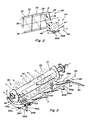
- a knife mounting assembly 51 as depicted in better detail in Figures 4-7 , and including one or more counter knife banks or knife ranks, can be provided to include knife blades or elements 80 so formed into aligned columnar arrangements to readily engage and project through the spaced slots 49 of floor portion 45 of concave pan assembly 48, as depicted in Figure 3 .
- the knife mounting assembly 51 includes a generally flat upper plate 54 positionable to extend generally horizontally across the flow path beneath floor portion 45 of the concave pan assembly 48, as illustrated in Figure 4 , end plates 56A and 56B at the opposite ends of the upper plate 54, and depending side wall portions 58A and 58B along the length of the upper plate 54 generally at or near the sides of the upper plate 54 and extending between the end plates 56A and 56B.
- connection members such as nut and bolt connectors 62
- connection members such as nut and bolt connectors 62
- connection members such as nut and bolt connectors 62
- lower portions 64A and 64B connected via positioning rods 66A and 66B to a lever assembly 68, to define a rotational axis extending through rotation points 60, the purpose and operation of which will be further addressed hereinafter.
- the upper plate 54 includes spaced slots 76 extending laterally across the upper plate 54 between the sides thereof and along the length thereof, through which slots 76 upper portions of installed knife blades or elements 80 project.
- the knife mounting assembly 51 is depicted in a normal, operational position, with knife blades or elements 80 extending through slots 76 in upper plate 54 and also through slots 49 in a floor portion 45 of concave pan assembly 48 into the flow passage 82 between rotary member 47 and the concave pan assembly 48.
- the knife blades or elements 52 of the rotary member 47 and the knife blades or elements 80 of knife mounting assembly 51 are so designed and installed relative to one another that they do not, under normal circumstances and operation, interfere with one another, but, rather, complement one another in chopping the residue passing between the rotary member 47 and the concave pan assembly 48 in flow passage 82.
- lever assembly 68 may be operated to effect, through the coupled movement of positioning rods 66A and 66B, a rotation of knife mounting assembly 51 about the axis of rotation through rotation points 60 ( Figure 4 ), the consequence of which is the retraction of the knife blades or elements 80 from the flow passage 82.
- Lever assembly 68 includes an operable lever 90 coupled at rotational axis 92 ( Figure 3 ) to a rotatable connecting rod 94 extending between sides 59A and 59B of concave pan assembly 48, which connecting rod 94 is attached to support links 96A and 96B.
- Support links 96A and 96B are respectively connected to positioning rods 66A and 66B.
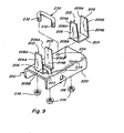
- FIGs 5-7 depict in greater detail further specifics of a preferred knife bank or knife rank construction 100 that can form a portion of the knife mounting assembly 51.
- Such knife bank or knife rank 100 includes a plurality of knife blades or elements 80 having base body portions 102 with apertures 104 therethrough and upper portions 106, shown here as having the form of an isosceles triangle, with cutting edges 108A and 108B.
- a spline connector 110 is provided and configured to extend through the aligned apertures 104 of a column of knife blades or elements 80 and to mate with such knife blades or elements so as to maintain the knife blades or elements in such column in an upright position at spaced intervals from one another.
- the spline connector 110 may take various forms, but is depicted in Figure 5 as comprising a pair of knife retainer members 112 that are of generally like design and configuration, sized and configured to be positionable side-by-side to one another within the apertures 104 in the base body portions 102 of the knife blades or elements 80.
- Such knife retainer members preferably include spaced lateral slits 114 along the bottom sides 116 thereof, which slits 114 are dimensioned to complementarily receive therein and to engage opposed side portions of the base body portions 102 of the knife blades or elements 80, adjacent to the apertures 104 therethrough, when the knife retainer members 112 are positioned extending through such apertures 104 and are moved into press-fit engagement with the knife blades or elements 80, with such engaged plurality of knife blades or elements and retainer members defining a knife formation.
- the slits 114 in the knife retainer members 112 are spaced to correspond to spacings 118 between slots 76 in the upper plate 54 of the knife mounting assembly 51, but there need not be a 1:1 correspondence between such slits 114 and slots 76, and knife blades or elements 80 need not be provided for every slot 76 in the upper plate 54 of the knife mounting assembly 51.
- the knife retainer members 112 will preferably fit snugly within the apertures 104 of the base body portions 102 of the knife blades or elements 80 when positioned side-by-side, and the knife retainer members 112 may therefore optionally be slightly tapered along at least portions of one or both sides thereof to facilitate the press fitting of such knife retainer members 112 into position.
- the preferred embodiment of the counter knife bank or knife rank 100 also includes a longitudinally extending support member 120 having an inverted U shape dimensioned to extend beneath and form a platform upon which the bases of the knife blades or elements 80 of the knife formation may rest and to which the knife formation is securely attached, such as preferably by, a plurality of U-bolt connectors 122 whose cross-pieces 124 extend laterally across the tops 126 of the retainer members 112, preferably within grooves 128 positioned along the tops 126 of the retainer members 112 to receive the cross-pieces 124 of the U-bolt connectors 122, and whose legs 130, which may be threaded, are attachable to the support member 120, such as through openings 132 in the support member 120 to underlying nuts 134 or other connection terminators.
- the sides 136A and 136B of the support member 120 preferably include a plurality of spaced openings 138 therealong registrable with openings 140 along the extent of at least one of the side wall portions 58A and 58B of the knife mounting assembly 51, through which registered openings 138, 140 bolts 142 or other connector members may be inserted to attach and secure the support member 120 to the knife mounting assembly 51.
- Such openings are preferably dimensioned to accept carriage bolts positioned therein from the interior sides of the legs 136A and 136B of the inverted U-shaped support member 120 and to prevent the rotation of such carriage bolts when washers 146 and nuts 148 are inserted on the projecting threaded ends of such carriage bolts 142 and tightened.
- the assembled counter knife bank or rank 100 can thus be easily installed as part of the knife mounting assembly 51 by positioning the knife blades or elements 80 of such assembled unit in registration with slots 76 in upper plate 54 of knife mounting assembly 51, by positioning openings 138 of the support member 120 in registration with openings 140 of side wall portions 58A and 58B, by inserting carriage bolts 142 through the respective aligned openings, and by tightening washers 146 and nuts 148 on the threaded ends of such carriage bolts to securely attach the assembled counter knife bank or knife rank 100 to knife mounting assembly 51.
- the assembled counter knife bank or knife rank 100 can be easily removed from the knife mounting assembly 51 by reversing the installation procedure, and the reversal of the cutting edges can be readily accomplished by reversing the orientation of the assembled counter knife bank or knife rank 100 relative to the knife mounting assembly 51 and re-installing such counter knife bank or knife rank 100 with such reversed orientation.
- the spline connector could have connector openings therethrough and be connected to the support member by one or more threaded members extending through the connector openings, such as by three nut and bolt connector pairs, two of which could be positioned at opposite ends of the spline connector and one of which could be intermediately positioned along the length of the spline connector, generally approximately centrally along the spline connector.
- the support member could have slits spaced along the length of the support member for receiving the base body portions of the knife blades or elements 80 and permitting positioning of the apertures in the base body portions below the top surface of the support member, and a spline connector could be installed through the apertures in such base body portions and beneath, rather than above, the top surface of the support member.
- the inserted spline connector could itself, because of a tight fit design, obviate the need for use of U-bolts or threaded members or other attachment members to secure the spline connector to the support member and/or to maintain the knife blades or elements of the counter knife bank or knife rank in a spaced, upright column.
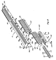
- one or more counter knife banks or knife ranks may be employed or required in order to span the entire length of the stationary knife assembly. If multiple knife banks or ranks are utilized, as shown in Figure 8 , such knife banks or knife ranks may be of the same or different lengths and configurations, and may include the same or differing numbers of knife blades or elements. For example, in the construction of Figure 8 , three counter knife bank or knife rank constructions are employed, two of which knife banks or knife ranks 100 are substantially identical and which include thirteen knife blades or elements 80. The third knife bank of knife rank 100' is highly similar to knife bank or knife rank 100, but includes fifteen knife blades or elements 80.
- lever assembly 68 is shown herein as being a manually operable assembly, it should be recognized and understood that other types of assemblies could be equally as well utilized, including constructions that are remotely controllable and actuatable and which may employ various types of motors or other actuator or drive members to effect desired operation.
- counter knife bank or knife rank constructions described hereinabove have been discussed primarily in relationship to and use with a combine that includes an axially arranged threshing system and a rotary chopper assembly as part of the crop residue distribution system for such combine, it should be understood and appreciated that the use of such counter knife bank or knife rank constructions is not limited to such systems and/or chopper assemblies or the chopper assembly positions addressed hereinabove and that such counter knife bank or knife rank constructions can be employed with other systems and chopper assemblies and with chopper assemblies located or positioned differently from what has been addressed hereinabove, including in or with non-integrated chopper assemblies and hood mount chopper systems.
Landscapes
- Life Sciences & Earth Sciences (AREA)
- Environmental Sciences (AREA)
- Harvester Elements (AREA)
- Threshing Machine Elements (AREA)
Claims (11)
- Ensemble couteau fixe pour un ensemble hacheur (46) d'une moissonneuse-batteuse agricole (20) comprenant :un ensemble de montage de couteau (51) comprenant une plaque supérieure longitudinale (54), généralement plate, comprenant des fentes (76) espacées le long de sa longueur, etune pluralité d'éléments de couteau (80) à double face comprenant des parties de corps de base (102) ayant des ouvertures alignées (104) et des parties supérieures (106) sous la forme d'un triangle isocèle avec une première arête de coupe (108A) et une seconde arête de coupe (108B), l'espacement entre les éléments de couteau (80) correspondant à l'espacement entre les fentes (76) dans la plaque supérieure (54),l'ensemble couteau fixe comprenant en plus au moins une barre de coupe (100, 100') qui comprend un élément de support (120), les éléments de couteau espacés à double face (80) et des organes d'assemblage de couteau (122, 128) pour fixer les éléments de couteau (80) à l'élément de support (120), etl'élément de support (120) étant fixé de façon réversible à la plaque supérieure (54) au moyen d'organes d'assemblage de support (142, 146, 148),caractérisé en ce que les organes d'assemblage de couteau (122, 128) comprennent un élément d'assemblage à rainure (128) qui s'étend au travers des ouvertures alignées (104).
- Ensemble couteau fixe selon la revendication 1, caractérisé en ce qu'il comprend une pluralité de barres de coupe (100, 100').
- Ensemble couteau fixe selon la revendications 1 ou 2, caractérisé en ce que l'ensemble de montage de couteau (51) comprend en plus des parties de paroi latérale longitudinales pendant vers le bas (58A, 58B) au niveau ou à côté des côtés de la plaque supérieure (54) et le long d'au moins une partie de sa longueur, et en ce que l'élément de support (120) comprend des parties de paroi latérale (136A, 136B) pour fixer de façon réversible l'élément de support (120) à la plaque supérieure (54) au niveau d'au moins une des parties de paroi latérale (58A, 58B) de la plaque supérieure (54) au moyen des organes d'assemblage de support (142, 146, 148)
- Ensemble couteau fixe selon l'une quelconque des revendications 1 à 3, caractérisé en ce que l'élément de support (120) a une section transversale en forme de U inversé.
- Ensemble couteau fixe selon l'une quelconque des revendications, caractérisé en ce que l'élément d'assemblage à rainure (110) est façonné sous la forme d'une paire d'éléments de retenue de couteau généralement semblables (112) comprenant :un côté inférieur (116) comportant une pluralité d'encoches latérales espacées (114) dimensionnées pour engager de façon complémentaire les sections de la partie de corps de base (102) des éléments de couteau (80) en dessous des ouvertures (104) dans un engagement en force, l'espacement entre les encoches latérales (114) correspondant à l'espacement entre les fentes (76) de la plaque supérieure (54) de l'ensemble de montage de couteau (51) ; et/ouun côté supérieur (126) comportant une pluralité de rainures espacées (128) pour coopérer avec des pièces transversales (124) des étriers en U (122) dotés de branches filetées (130) qui sont insérées dans des ouvertures pour raccord (132) de l'élément de support (120) et coopérer avec des écrous (134) afin de fixer les éléments de couteau (80) à l'élément de support (120).
- Ensemble couteau fixe selon l'une quelconque des revendications précédentes, caractérisé en ce que l'ensemble de montage de couteau (51) comprend des plaques latérales d'extrémité (56A, 56B) à des côtés opposés de la plaque supérieure (54).
- Ensemble hacheur (46) d'une moissonneuse-batteuse agricole (20) comprenant un organe rotatif (47),
un ensemble de carter concave (48) espacé en dessous de l'organe rotatif et s'étendant généralement parallèlement à l'organe rotatif (47) pour définir un passage d'écoulement de matière (82) entre l'organe rotatif (47) et l'ensemble de carter concave (48), l'ensemble de carter concave (48) comprenant des éléments latéraux (59A, 59B) sur les deux côtés du passage d'écoulement de matière (82),
caractérisé en ce que l'ensemble hacheur (46) comprend un ensemble couteau fixe selon la revendication 6 dont les plaques d'extrémité latérales (56A, 56B) sont accouplées aux membres latéraux (59A, 59B) de l'ensemble de carter concave au moyen d'organes d'assemblage (62) et qui peut être positionné de telle manière que les éléments de couteau (80/206) font saillie dans le passage d'écoulement de matière (82). - Ensemble hacheur selon la revendication 7, caractérisé en ce que :l'ensemble de carter concave (48) comprend en plus une partie de fond (45) s'étendant longitudinalement entre les deux éléments latéraux (59A, 59B), la partie de fond (45) comprenant des fentes latérales espacées (49), et l'espacement entre les fentes latérales (49) correspondant à l'espacement entre les fentes (76) de la plaque supérieure (54) de l'ensemble de montage de couteau (51), etl'ensemble couteau fixe peut être positionné par rapport à la partie de fond (45) de l'ensemble de carter concave (48) de telle manière que les éléments de couteau à double face (80/206) font saillie à travers les fentes latérales espacées (49) de la partie de fond.
- Ensemble hacheur selon la revendication 7 ou 8, caractérisé en ce que les organes d'assemblage (62) qui assemblent l'ensemble couteau fixe aux éléments latéraux (59A, 59B) de l'ensemble de carter concave (48) définissent deux points de rotation (60) et un axe de rotation associé pour que l'ensemble couteau fixe retire les éléments de couteau à double face (80/206) du passage d'écoulement de matière (82).
- Ensemble hacheur selon la revendication 9, caractérisé en ce qu'il comprend un mécanisme de commande (68) pour commander la rotation de l'ensemble couteau fixe autour de l'axe de rotation s'étendant au travers des points de rotation (60).
- Procédé pour inverser un ensemble couteau fixe selon l'une quelconque des revendications 1 à 6, le procédé consistant à :enlever la première barre de coupe (100, 100') d'un seul bloc de l'ensemble couteau fixe en détachant son élément de support (120) de la plaque supérieure (54) de l'ensemble de montage de couteau (51) après avoir desserré ou enlevé les organes d'assemblage de support (142, 146, 148),inverser l'orientation de la première barre de coupe (100, 100') par rapport à l'ensemble de montage de couteau de manière à ce que les secondes arêtes de coupe (108B) des éléments de couteau à double face (80) soient montées à sensiblement la même position que la position des premières arêtes de coupe (108A) avant le détachement de la première barre de coupe (100, 100'),fixer la première barre de coupe (100, 100') d'un seul bloc à l'ensemble couteau fixe en fixant son élément de support (120) à la plaque supérieure (54) de l'ensemble de montage de couteau (51) en fixant ou en insérant les organes d'assemblage de support (142, 146, 148), etrépéter les étapes précédentes pour chaque barre de coupe suivante (100, 100') de l'ensemble couteau fixe.
Applications Claiming Priority (1)
| Application Number | Priority Date | Filing Date | Title |
|---|---|---|---|
| US11/810,213 US7484350B2 (en) | 2007-06-05 | 2007-06-05 | Reversable counter knife bank |
Publications (2)
| Publication Number | Publication Date |
|---|---|
| EP2000019A1 EP2000019A1 (fr) | 2008-12-10 |
| EP2000019B1 true EP2000019B1 (fr) | 2015-12-23 |
Family
ID=39545041
Family Applications (1)
| Application Number | Title | Priority Date | Filing Date |
|---|---|---|---|
| EP08157655.5A Active EP2000019B1 (fr) | 2007-06-05 | 2008-06-05 | Ensemble peigne fixe pour hacheur de paille |
Country Status (2)
| Country | Link |
|---|---|
| US (1) | US7484350B2 (fr) |
| EP (1) | EP2000019B1 (fr) |
Cited By (1)
| Publication number | Priority date | Publication date | Assignee | Title |
|---|---|---|---|---|
| EP4494448A1 (fr) * | 2023-04-13 | 2025-01-22 | CNH Industrial America LLC | Contre-couteaux hacheur de paille avec lame entre le contre-couteau et le pivot du couteau |
Families Citing this family (23)
| Publication number | Priority date | Publication date | Assignee | Title |
|---|---|---|---|---|
| CA2678444C (fr) * | 2007-04-05 | 2012-05-29 | Iowa State University Research Foundation, Inc. | Dispositif de decoupe de materiau a double cisaillement |
| BRPI0818304A2 (pt) * | 2007-11-01 | 2014-09-23 | Univ Iowa State Res Found Inc | Unidade de movimento de ar para melhoria de desempenho de transporte, separação ou de máquina de ceifar e debulhar de biomassa. |
| US7867072B2 (en) * | 2009-03-13 | 2011-01-11 | Cnh America Llc | Rotor tine and rotary element configuration for crop residue treatment systems |
| DE102009030548B4 (de) * | 2009-06-25 | 2013-07-04 | Biso Schrattenecker Gmbh | Erntevorsatz für eine Erntemaschine |
| US8834244B2 (en) * | 2012-07-25 | 2014-09-16 | Cnh Industrial America Llc | Flow distribution system for controlling application width of residual crop material |
| US8920227B2 (en) | 2013-01-02 | 2014-12-30 | Cnh Industrial America Llc | Spring loaded counter knife bank assembly |
| EP2991471B1 (fr) * | 2013-05-01 | 2018-08-15 | CNH Industrial Belgium N.V. | Prévention contre les débris pour rangée de contre-lames |
| WO2014181171A1 (fr) * | 2013-05-10 | 2014-11-13 | Agco Corporation | Procédé et système de sortie de mog de crible |
| DE102013105836A1 (de) * | 2013-06-06 | 2014-12-11 | Claas Selbstfahrende Erntemaschinen Gmbh | Mähdrescher |
| DE102013108292A1 (de) * | 2013-08-01 | 2015-02-05 | Claas Selbstfahrende Erntemaschinen Gmbh | Mähdrescher mit einer Häckselvorrichtung |
| US9497903B2 (en) * | 2014-10-16 | 2016-11-22 | Agco Corporation | Combine harvester residue management system |
| US9913433B2 (en) * | 2015-01-30 | 2018-03-13 | Cnh Industrial America Llc | Selectable knife tray arrangement |
| BE1023152B1 (nl) | 2015-08-28 | 2016-12-02 | Cnh Industrial Belgium Nv | Oogstmachine met feedbackregeling van hakselparameters |
| US9743586B2 (en) * | 2015-09-17 | 2017-08-29 | Agco Corporation | Mounting arrangement for a straw chopper and chaff spreader in a combine harvester residue management system |
| US10225992B2 (en) | 2015-10-09 | 2019-03-12 | Cnh Industrial America Llc | Single fastener attachment for chopper knives |
| US10674671B2 (en) * | 2017-12-08 | 2020-06-09 | Cnh Industrial America Llc | Auxiliary processing system |
| US11154013B2 (en) * | 2019-06-27 | 2021-10-26 | Deere & Company | Rail interrupter |
| PL72623Y1 (pl) * | 2020-06-02 | 2022-07-04 | Batyra Henryk Masz Rolnicze | Wał tnący |
| PL72624Y1 (pl) * | 2020-06-02 | 2022-07-04 | Batyra Henryk Masz Rolnicze | Wał tnący |
| EP4445717B1 (fr) * | 2023-04-13 | 2025-12-17 | CNH Industrial America LLC | Hache-paille pour moissonneuse-batteuse |
| EP4445718B1 (fr) | 2023-04-13 | 2026-02-25 | CNH Industrial America LLC | Porte-couteaux concentriques à lame fixe pour moissonneuses agricoles |
| US20250194469A1 (en) | 2023-12-13 | 2025-06-19 | Cnh Industrial America Llc | Method for reduction of chopper recut |
| US20250295076A1 (en) | 2024-03-22 | 2025-09-25 | Cnh Industrial America Llc | Knife holder for counterknife bank assembly for combine harvester |
Family Cites Families (25)
| Publication number | Priority date | Publication date | Assignee | Title |
|---|---|---|---|---|
| BE558601A (fr) | ||||
| DE823061C (de) | 1950-05-23 | 1951-11-29 | Julius Lanvermeyer | Haeckselmaschine |
| DE832357C (de) * | 1950-10-29 | 1952-02-25 | Julius Lanvermeyer | Haeckselmaschine |
| DE923514C (de) * | 1953-05-17 | 1955-02-14 | Horstkoetter & Deppe | Messerhalter fuer Strohschneidemaschinen |
| US2842175A (en) * | 1955-10-24 | 1958-07-08 | Ernest S Thompson | Straw chopper for combine |
| DE1140774B (de) * | 1960-07-14 | 1962-12-06 | John Deere Lanz Ag | Vorrichtung zum Zerkleinern des aus dem Dreschwerk von Dreschmaschinen oder Maehdreschern anfallenden Strohes |
| SE368657B (fr) * | 1972-11-16 | 1974-07-15 | Groenbergs Giuteri & Kvarnfab | |
| CA1035657A (fr) * | 1976-01-23 | 1978-08-01 | Carl H. Kersey | Batteuse/hacheuse a elements sur supports distincts |
| DE3474248D1 (en) * | 1984-07-19 | 1988-11-03 | Deere & Co | Chopper device, especially for harvesting machines |
| US4637406A (en) * | 1984-08-09 | 1987-01-20 | Hesston Corporation | Chaff and straw spreading attachment for combines |
| NL8403377A (nl) * | 1984-11-06 | 1986-06-02 | Schuitemaker Mach Bv | Opraaploswagen. |
| DE9305838U1 (de) * | 1993-04-20 | 1993-06-17 | Doppstadt, Werner, 5620 Velbert | Zerkleinerungsmaschine mit Nachzerkleinerung für Müll |
| US5482508A (en) * | 1995-03-31 | 1996-01-09 | Redekop; Leo L. | Apparatus for chopping and discharging straw from a combine harvester |
| US5542883A (en) * | 1995-06-02 | 1996-08-06 | Dutch Industries Ltd. | Straw spreading system |
| DE19607915C2 (de) | 1996-03-01 | 1999-05-06 | Strautmann & Soehne | Schneivorrichtung für Halm- und Blattgut |
| US5833533A (en) * | 1996-05-09 | 1998-11-10 | Class Kgaa | Harvester thresher |
| DE19706429C1 (de) * | 1997-02-19 | 1998-04-16 | Fortschritt Erntemaschinen | Schneideinrichtung für landwirtschaftliche Erntemaschinen |
| DE19722793A1 (de) * | 1997-05-30 | 1998-12-03 | Claas Selbstfahr Erntemasch | Mähdrescher |
| DE19749338C2 (de) | 1997-11-07 | 2000-02-17 | Franz Schrattenecker | Häcksler zum Zerkleinern von Halmgut, vorzugsweise von Stroh |
| DE19832463C2 (de) * | 1998-07-18 | 2002-07-04 | Krone Bernhard Gmbh Maschf | Schneideinrichtung für landwirtschaftliche Erntemaschinen |
| US6298646B1 (en) * | 2000-03-01 | 2001-10-09 | Hay & Forage Industries | Square baler with infeed cutter |
| US6616528B2 (en) * | 2001-12-12 | 2003-09-09 | Case Corporation | Vertical crop residue chopper and spreader |
| US6769239B1 (en) * | 2003-03-07 | 2004-08-03 | New Holland North America, Inc. | Non-trash sensitive rotor knife guide plates |
| DE202004014704U1 (de) * | 2004-09-17 | 2004-11-18 | B. Strautmann & Söhne GmbH u. Co. KG | Schneidwerk für Erntemaschinen |
| US7544127B2 (en) | 2005-06-30 | 2009-06-09 | Deere & Company | Straw chopper for combine with adjustable stationary knife bank |
-
2007
- 2007-06-05 US US11/810,213 patent/US7484350B2/en active Active
-
2008
- 2008-06-05 EP EP08157655.5A patent/EP2000019B1/fr active Active
Cited By (1)
| Publication number | Priority date | Publication date | Assignee | Title |
|---|---|---|---|---|
| EP4494448A1 (fr) * | 2023-04-13 | 2025-01-22 | CNH Industrial America LLC | Contre-couteaux hacheur de paille avec lame entre le contre-couteau et le pivot du couteau |
Also Published As
| Publication number | Publication date |
|---|---|
| EP2000019A1 (fr) | 2008-12-10 |
| US20080305842A1 (en) | 2008-12-11 |
| US7484350B2 (en) | 2009-02-03 |
Similar Documents
| Publication | Publication Date | Title |
|---|---|---|
| EP2000019B1 (fr) | Ensemble peigne fixe pour hacheur de paille | |
| US8092286B2 (en) | Concave pan portion of an integral chopper assembly of a combine harvester | |
| US7677965B2 (en) | Combine harvester residue chopper active counter knife assembly | |
| US6494782B1 (en) | Threshing and separating unit of axial flow combines | |
| US7867072B2 (en) | Rotor tine and rotary element configuration for crop residue treatment systems | |
| US7104883B2 (en) | Straw chopper blade | |
| US6616528B2 (en) | Vertical crop residue chopper and spreader | |
| CA2119709C (fr) | Element pour l'insertion de la recolte dans une moissonneuse-batteuse a batteur axial | |
| US6783453B2 (en) | Mounting assembly for straw chopper blades | |
| EP2993968B1 (fr) | Installation de hacheur/ventilateur pour un organe de coupe utilisé sur une récolteuse agricole | |
| US7022013B1 (en) | Axial flow combine harvester with adaptable separating unit | |
| EP1754408B1 (fr) | Hache-paille avec un ventilateur | |
| US8187064B2 (en) | Combine chopper with overload protection | |
| US20020169011A1 (en) | Flail straw chopper blade | |
| EP1529435B1 (fr) | Moissonneuse-batteuse à écoulement axial avec dispositif de battage adaptable | |
| US11154013B2 (en) | Rail interrupter | |
| EP3345472B1 (fr) | Dissipateur de résidus de cultures pour moissonneuse-batteuse | |
| GB2407750A (en) | Axial flow combine harvester with adaptable separating unit |
Legal Events
| Date | Code | Title | Description |
|---|---|---|---|
| PUAI | Public reference made under article 153(3) epc to a published international application that has entered the european phase |
Free format text: ORIGINAL CODE: 0009012 |
|
| AK | Designated contracting states |
Kind code of ref document: A1 Designated state(s): AT BE BG CH CY CZ DE DK EE ES FI FR GB GR HR HU IE IS IT LI LT LU LV MC MT NL NO PL PT RO SE SI SK TR |
|
| AX | Request for extension of the european patent |
Extension state: AL BA MK RS |
|
| 17P | Request for examination filed |
Effective date: 20090610 |
|
| 17Q | First examination report despatched |
Effective date: 20090717 |
|
| AKX | Designation fees paid |
Designated state(s): AT BE BG CH CY CZ DE DK EE ES FI FR GB GR HR HU IE IS IT LI LT LU LV MC MT NL NO PL PT RO SE SI SK TR |
|
| RAP1 | Party data changed (applicant data changed or rights of an application transferred) |
Owner name: CNH INDUSTRIAL BELGIUM NV |
|
| GRAP | Despatch of communication of intention to grant a patent |
Free format text: ORIGINAL CODE: EPIDOSNIGR1 |
|
| RIC1 | Information provided on ipc code assigned before grant |
Ipc: A01F 12/40 20060101AFI20150610BHEP Ipc: A01F 29/09 20100101ALI20150610BHEP |
|
| INTG | Intention to grant announced |
Effective date: 20150629 |
|
| GRAS | Grant fee paid |
Free format text: ORIGINAL CODE: EPIDOSNIGR3 |
|
| GRAA | (expected) grant |
Free format text: ORIGINAL CODE: 0009210 |
|
| AK | Designated contracting states |
Kind code of ref document: B1 Designated state(s): AT BE BG CH CY CZ DE DK EE ES FI FR GB GR HR HU IE IS IT LI LT LU LV MC MT NL NO PL PT RO SE SI SK TR |
|
| REG | Reference to a national code |
Ref country code: GB Ref legal event code: FG4D |
|
| REG | Reference to a national code |
Ref country code: CH Ref legal event code: EP |
|
| REG | Reference to a national code |
Ref country code: IE Ref legal event code: FG4D |
|
| REG | Reference to a national code |
Ref country code: AT Ref legal event code: REF Ref document number: 766091 Country of ref document: AT Kind code of ref document: T Effective date: 20160115 |
|
| REG | Reference to a national code |
Ref country code: DE Ref legal event code: R096 Ref document number: 602008041639 Country of ref document: DE |
|
| REG | Reference to a national code |
Ref country code: FR Ref legal event code: PLFP Year of fee payment: 9 |
|
| REG | Reference to a national code |
Ref country code: LT Ref legal event code: MG4D |
|
| REG | Reference to a national code |
Ref country code: NL Ref legal event code: MP Effective date: 20151223 |
|
| PG25 | Lapsed in a contracting state [announced via postgrant information from national office to epo] |
Ref country code: LT Free format text: LAPSE BECAUSE OF FAILURE TO SUBMIT A TRANSLATION OF THE DESCRIPTION OR TO PAY THE FEE WITHIN THE PRESCRIBED TIME-LIMIT Effective date: 20151223 Ref country code: NO Free format text: LAPSE BECAUSE OF FAILURE TO SUBMIT A TRANSLATION OF THE DESCRIPTION OR TO PAY THE FEE WITHIN THE PRESCRIBED TIME-LIMIT Effective date: 20160323 Ref country code: HR Free format text: LAPSE BECAUSE OF FAILURE TO SUBMIT A TRANSLATION OF THE DESCRIPTION OR TO PAY THE FEE WITHIN THE PRESCRIBED TIME-LIMIT Effective date: 20151223 |
|
| REG | Reference to a national code |
Ref country code: AT Ref legal event code: MK05 Ref document number: 766091 Country of ref document: AT Kind code of ref document: T Effective date: 20151223 |
|
| PG25 | Lapsed in a contracting state [announced via postgrant information from national office to epo] |
Ref country code: LV Free format text: LAPSE BECAUSE OF FAILURE TO SUBMIT A TRANSLATION OF THE DESCRIPTION OR TO PAY THE FEE WITHIN THE PRESCRIBED TIME-LIMIT Effective date: 20151223 Ref country code: SE Free format text: LAPSE BECAUSE OF FAILURE TO SUBMIT A TRANSLATION OF THE DESCRIPTION OR TO PAY THE FEE WITHIN THE PRESCRIBED TIME-LIMIT Effective date: 20151223 Ref country code: GR Free format text: LAPSE BECAUSE OF FAILURE TO SUBMIT A TRANSLATION OF THE DESCRIPTION OR TO PAY THE FEE WITHIN THE PRESCRIBED TIME-LIMIT Effective date: 20160324 Ref country code: NL Free format text: LAPSE BECAUSE OF FAILURE TO SUBMIT A TRANSLATION OF THE DESCRIPTION OR TO PAY THE FEE WITHIN THE PRESCRIBED TIME-LIMIT Effective date: 20151223 Ref country code: FI Free format text: LAPSE BECAUSE OF FAILURE TO SUBMIT A TRANSLATION OF THE DESCRIPTION OR TO PAY THE FEE WITHIN THE PRESCRIBED TIME-LIMIT Effective date: 20151223 |
|
| PG25 | Lapsed in a contracting state [announced via postgrant information from national office to epo] |
Ref country code: CZ Free format text: LAPSE BECAUSE OF FAILURE TO SUBMIT A TRANSLATION OF THE DESCRIPTION OR TO PAY THE FEE WITHIN THE PRESCRIBED TIME-LIMIT Effective date: 20151223 Ref country code: ES Free format text: LAPSE BECAUSE OF FAILURE TO SUBMIT A TRANSLATION OF THE DESCRIPTION OR TO PAY THE FEE WITHIN THE PRESCRIBED TIME-LIMIT Effective date: 20151223 |
|
| PG25 | Lapsed in a contracting state [announced via postgrant information from national office to epo] |
Ref country code: EE Free format text: LAPSE BECAUSE OF FAILURE TO SUBMIT A TRANSLATION OF THE DESCRIPTION OR TO PAY THE FEE WITHIN THE PRESCRIBED TIME-LIMIT Effective date: 20151223 Ref country code: RO Free format text: LAPSE BECAUSE OF FAILURE TO SUBMIT A TRANSLATION OF THE DESCRIPTION OR TO PAY THE FEE WITHIN THE PRESCRIBED TIME-LIMIT Effective date: 20151223 Ref country code: PL Free format text: LAPSE BECAUSE OF FAILURE TO SUBMIT A TRANSLATION OF THE DESCRIPTION OR TO PAY THE FEE WITHIN THE PRESCRIBED TIME-LIMIT Effective date: 20151223 Ref country code: SK Free format text: LAPSE BECAUSE OF FAILURE TO SUBMIT A TRANSLATION OF THE DESCRIPTION OR TO PAY THE FEE WITHIN THE PRESCRIBED TIME-LIMIT Effective date: 20151223 Ref country code: PT Free format text: LAPSE BECAUSE OF FAILURE TO SUBMIT A TRANSLATION OF THE DESCRIPTION OR TO PAY THE FEE WITHIN THE PRESCRIBED TIME-LIMIT Effective date: 20160426 Ref country code: IS Free format text: LAPSE BECAUSE OF FAILURE TO SUBMIT A TRANSLATION OF THE DESCRIPTION OR TO PAY THE FEE WITHIN THE PRESCRIBED TIME-LIMIT Effective date: 20160423 Ref country code: AT Free format text: LAPSE BECAUSE OF FAILURE TO SUBMIT A TRANSLATION OF THE DESCRIPTION OR TO PAY THE FEE WITHIN THE PRESCRIBED TIME-LIMIT Effective date: 20151223 |
|
| REG | Reference to a national code |
Ref country code: DE Ref legal event code: R097 Ref document number: 602008041639 Country of ref document: DE |
|
| PLBE | No opposition filed within time limit |
Free format text: ORIGINAL CODE: 0009261 |
|
| STAA | Information on the status of an ep patent application or granted ep patent |
Free format text: STATUS: NO OPPOSITION FILED WITHIN TIME LIMIT |
|
| PG25 | Lapsed in a contracting state [announced via postgrant information from national office to epo] |
Ref country code: DK Free format text: LAPSE BECAUSE OF FAILURE TO SUBMIT A TRANSLATION OF THE DESCRIPTION OR TO PAY THE FEE WITHIN THE PRESCRIBED TIME-LIMIT Effective date: 20151223 |
|
| 26N | No opposition filed |
Effective date: 20160926 |
|
| PG25 | Lapsed in a contracting state [announced via postgrant information from national office to epo] |
Ref country code: MC Free format text: LAPSE BECAUSE OF FAILURE TO SUBMIT A TRANSLATION OF THE DESCRIPTION OR TO PAY THE FEE WITHIN THE PRESCRIBED TIME-LIMIT Effective date: 20151223 |
|
| REG | Reference to a national code |
Ref country code: CH Ref legal event code: PL |
|
| PG25 | Lapsed in a contracting state [announced via postgrant information from national office to epo] |
Ref country code: SI Free format text: LAPSE BECAUSE OF FAILURE TO SUBMIT A TRANSLATION OF THE DESCRIPTION OR TO PAY THE FEE WITHIN THE PRESCRIBED TIME-LIMIT Effective date: 20151223 |
|
| REG | Reference to a national code |
Ref country code: IE Ref legal event code: MM4A |
|
| REG | Reference to a national code |
Ref country code: FR Ref legal event code: PLFP Year of fee payment: 10 |
|
| PG25 | Lapsed in a contracting state [announced via postgrant information from national office to epo] |
Ref country code: LI Free format text: LAPSE BECAUSE OF NON-PAYMENT OF DUE FEES Effective date: 20160630 Ref country code: CH Free format text: LAPSE BECAUSE OF NON-PAYMENT OF DUE FEES Effective date: 20160630 |
|
| PG25 | Lapsed in a contracting state [announced via postgrant information from national office to epo] |
Ref country code: IE Free format text: LAPSE BECAUSE OF NON-PAYMENT OF DUE FEES Effective date: 20160605 |
|
| REG | Reference to a national code |
Ref country code: FR Ref legal event code: PLFP Year of fee payment: 11 |
|
| PG25 | Lapsed in a contracting state [announced via postgrant information from national office to epo] |
Ref country code: HU Free format text: LAPSE BECAUSE OF FAILURE TO SUBMIT A TRANSLATION OF THE DESCRIPTION OR TO PAY THE FEE WITHIN THE PRESCRIBED TIME-LIMIT; INVALID AB INITIO Effective date: 20080605 Ref country code: CY Free format text: LAPSE BECAUSE OF FAILURE TO SUBMIT A TRANSLATION OF THE DESCRIPTION OR TO PAY THE FEE WITHIN THE PRESCRIBED TIME-LIMIT Effective date: 20151223 |
|
| PG25 | Lapsed in a contracting state [announced via postgrant information from national office to epo] |
Ref country code: MT Free format text: LAPSE BECAUSE OF NON-PAYMENT OF DUE FEES Effective date: 20160630 Ref country code: TR Free format text: LAPSE BECAUSE OF FAILURE TO SUBMIT A TRANSLATION OF THE DESCRIPTION OR TO PAY THE FEE WITHIN THE PRESCRIBED TIME-LIMIT Effective date: 20151223 Ref country code: LU Free format text: LAPSE BECAUSE OF NON-PAYMENT OF DUE FEES Effective date: 20160605 |
|
| PG25 | Lapsed in a contracting state [announced via postgrant information from national office to epo] |
Ref country code: BG Free format text: LAPSE BECAUSE OF FAILURE TO SUBMIT A TRANSLATION OF THE DESCRIPTION OR TO PAY THE FEE WITHIN THE PRESCRIBED TIME-LIMIT Effective date: 20151223 |
|
| REG | Reference to a national code |
Ref country code: DE Ref legal event code: R082 Ref document number: 602008041639 Country of ref document: DE Representative=s name: MEISSNER BOLTE PATENTANWAELTE RECHTSANWAELTE P, DE |
|
| PGFP | Annual fee paid to national office [announced via postgrant information from national office to epo] |
Ref country code: GB Payment date: 20200620 Year of fee payment: 13 Ref country code: BE Payment date: 20200620 Year of fee payment: 13 |
|
| REG | Reference to a national code |
Ref country code: DE Ref legal event code: R084 Ref document number: 602008041639 Country of ref document: DE |
|
| GBPC | Gb: european patent ceased through non-payment of renewal fee |
Effective date: 20210605 |
|
| REG | Reference to a national code |
Ref country code: BE Ref legal event code: MM Effective date: 20210630 |
|
| PG25 | Lapsed in a contracting state [announced via postgrant information from national office to epo] |
Ref country code: GB Free format text: LAPSE BECAUSE OF NON-PAYMENT OF DUE FEES Effective date: 20210605 |
|
| PG25 | Lapsed in a contracting state [announced via postgrant information from national office to epo] |
Ref country code: BE Free format text: LAPSE BECAUSE OF NON-PAYMENT OF DUE FEES Effective date: 20210630 |
|
| PGFP | Annual fee paid to national office [announced via postgrant information from national office to epo] |
Ref country code: IT Payment date: 20230612 Year of fee payment: 16 |
|
| PG25 | Lapsed in a contracting state [announced via postgrant information from national office to epo] |
Ref country code: IT Free format text: LAPSE BECAUSE OF NON-PAYMENT OF DUE FEES Effective date: 20240605 |
|
| PGFP | Annual fee paid to national office [announced via postgrant information from national office to epo] |
Ref country code: DE Payment date: 20250626 Year of fee payment: 18 |
|
| PGFP | Annual fee paid to national office [announced via postgrant information from national office to epo] |
Ref country code: FR Payment date: 20250624 Year of fee payment: 18 |