EP2000212A1 - Dispositif de prévention d'obturation - Google Patents
Dispositif de prévention d'obturation Download PDFInfo
- Publication number
- EP2000212A1 EP2000212A1 EP07109553A EP07109553A EP2000212A1 EP 2000212 A1 EP2000212 A1 EP 2000212A1 EP 07109553 A EP07109553 A EP 07109553A EP 07109553 A EP07109553 A EP 07109553A EP 2000212 A1 EP2000212 A1 EP 2000212A1
- Authority
- EP
- European Patent Office
- Prior art keywords
- prevention device
- milling
- plugging prevention
- cup
- plugging
- Prior art date
- Legal status (The legal status is an assumption and is not a legal conclusion. Google has not performed a legal analysis and makes no representation as to the accuracy of the status listed.)
- Withdrawn
Links
Images

Classifications
-
- B—PERFORMING OPERATIONS; TRANSPORTING
- B02—CRUSHING, PULVERISING, OR DISINTEGRATING; PREPARATORY TREATMENT OF GRAIN FOR MILLING
- B02C—CRUSHING, PULVERISING, OR DISINTEGRATING IN GENERAL; MILLING GRAIN
- B02C18/00—Disintegrating by knives or other cutting or tearing members which chop material into fragments
- B02C18/06—Disintegrating by knives or other cutting or tearing members which chop material into fragments with rotating knives
- B02C18/062—Disintegrating by knives or other cutting or tearing members which chop material into fragments with rotating knives with rotor elements extending axially in close radial proximity of a concentrically arranged slotted or perforated ring
Definitions
- the present invention relates to a plugging prevention device according to the preamble of independent claim 1 and more particularly to a mill according to independent claim 9.
- Such plugging prevention devices can be used for improving milling processes of mills having a hollow body closed by a milling cup in which a rotor is rotatably arranged wherein the milling cup has a bottom part and a side-wall part with openings.
- processes include milling of various goods and substances.
- a source material is often mixed with a binder in a mixer.
- wet mills can be used for milling said mixture previous of drying the mixture, e.g. in a fluidized-bed dryer.
- Such wet mills can comprise a hollow body, for example having the shape of a hollow cylinder, which is closed at its bottom end by a milling cup.
- the milling cup usually has a side-wall part with a plurality of openings and a bottom part closing the milling cup in a downward direction.
- a rotator is mounted inside the milling cup .
- the mill can additionally have a housing surrounding the milling cup in which a drive can be arranged for rotating the rotator wherein the drive is connected to the rotator.
- the milling good can be fed into the hollow body at a top part of the wet mill. There starting, the milling good flows down into the direction of the milling cup typically by means of gravitation. Then, the rotating rotator moves the milling good onto the side-wall part of the milling cup having openings such that it is pressed through the openings of the side-wall part. The milling good being pressed through the openings can be gathered inside the housing and transferred to following processing steps such as for example to the fluidized-bed dryer.
- plugging can occur in the mill reducing the efficiency of the milling wherein such plugging effects depend on the properties of the milling good and the arrangement of the mill.
- lumps of milling good are often built in such mills. Lumps can enhance plugging effects in mills such that the milling efficiency is additionally reduced.
- the milling good including its lumps can be retained by the bottom part of the milling cup before being pressed through the openings of the side-wall part of the milling cup by the rotator. This can cause an accumulation of the milling good inside the mill until the mill is more or less completely stuck. At this stage the rotator moves parts of the accumulated milling good around the milling cup without substantially pressing any milling good out of the openings of the side-wall part of the milling cup.
- the invention deals with a plugging prevention device for a mill, in particular a wet mill, having a hollow body closed by a milling cup in which a rotor is rotatably arranged wherein the milling cup has a bottom part and a side-wall part with openings.
- the plugging prevention device comprises a striking section and interconnecting means wherein the plugging prevention device is arrangeable in the mill such that the striking section at least partly covers the bottom part of the milling cup and such that the plugging prevention device is torque proofly connected with the rotor via the interconnecting means.
- cover in this context relates to covering with respect to the regular direction of flow of the milling good such that, in use of the plugging prevention device, a milling good can not directly move onto the bottom part of the milling cup. It also includes covering the bottom part of the milling cup only while the striking section is rotating such that the striking section can also be shaped in such a manner that its geometric area of rotation covers the bottom part of the milling cup.
- such a plugging prevention device being arranged inside a mill rotates together with the rotator due to its torque proof connection with the rotator.
- Such rotation can for example be performed at about seven hundred rounds per minute.
- the milling good moving, for example flowing, into the direction of the bottom part of the milling cup hits onto the rotating striking section of the plugging prevention device.
- centrifugal forces are transmitted to the milling good such that it is moved into direction of the side-wall part of the milling cup.
- the rotator is affected by the rotator and pressed through the openings of the side-wall part of the milling cup.
- lumps of milling good can be fractured such that essentially no lumps are present in the milling good while being pressed though the side-wall part of the milling cup by the rotator.
- the striking section of the plugging prevention device can be provided with a coarse surface facing the milling good such that the centrifugal forces can efficiently be transmitted to the milling good. Further, the surface facing the milling good of striking section of the plugging prevention device can be provided with cutting tools for improving the fracturing of lumps.
- the striking section completely covers the bottom part of the milling cup.
- Such a striking section allows essentially to prevent a movement of milling good onto the bottom part of the milling cup even if the rotator rotates at a comparable low speed.
- the interconnecting means preferably comprises a profiled receiver.
- a receiver With such a receiver the torque proof connection between the plugging prevention device and the rotator can easily be provided.
- the receiver can be shaped as a squared through hole such that the squared through hole can be mounted on a corresponding squared part of a rotational axle.
- the striking section comprises a circular disk.
- a striking section provides a comparably large area where the milling good can hit on such that fracturing of lumps in the milling good can be optimized. Further, such a plugging prevention device is comparably easy to manufacture.
- the disk has through holes such as for example four equally distributed circular through holes.
- Such through holes improve accessibility of the space between the plugging prevention device and the milling cup while the plugging prevention device is not rotating. This can for example be an advantage for cleaning the mill, in particular for exhausting milling good out of the space between the plugging prevention device and the milling cup.
- the disk preferably has recesses at its outer edge projecting into the direction of the center of the disk. Such recesses can further improve accessibility of the space between the plugging prevention device and the milling cup.
- the striking section comprises a circular cone wherein the tip of the cone preferably faces away from the bottom part of the milling cup.
- the milling good hitting the striking section can additionally be moved towards the side-wall part of the milling cup.
- the striking section comprises a circular truncated cone.
- a second aspect of the invention deals with a mill, such as for example a wet mill, having a hollow body closed by a milling cup in which a rotor is rotatably arranged wherein the milling cup has a bottom part and a side-wall part with openings.
- a plugging prevention device as described above is arranged such that the striking section of the plugging prevention device at least partly covers the bottom part of the milling cup and such that the plugging prevention device is torque proofly connected with the rotor via the interconnecting means.
- the rotor is connected with further interconnecting means corresponding to the interconnecting means of the plugging prevention device and the further interconnecting means are interlocked with the interconnecting means of the plugging prevention device.
- the further interconnecting means can be arranged at a rotational axle.
- the plugging prevention device is preferably arranged inside the milling cup. Thereby, a compact arrangement of the mill according to the invention is possible.
- the plugging prevention device is arranged spaced from the bottom part of the milling cup.
- the arrangement of the mill can be optimized with respect to the properties of the milling good and the application of the mill.
- the side-wall part of the milling cup is usually conically shaped, the striking section can be enlarged with increasing distance from the bottom part of the milling cup.
- the distance can be optimized such that size of the striking section can be as large as possible without essentially covering the side-wall part of the milling cup.
- Fig. 1 shows a cross sectional side view of a mill according to the invention with a first embodiment of a plugging prevention device according to the invention
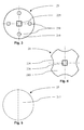
- Fig. 2 shows a top view on the plugging prevention device from of the mill from Fig. 1 ;
- Fig. 3 shows a top view on a second embodiment of a plugging prevention device according to the invention
- Fig. 4 shows a top view on a third embodiment of a plugging prevention device according to the invention.
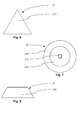
- Fig. 5 shows a top view on a fourth embodiment of a plugging prevention device according to the invention.
- Fig. 6 shows a side view on the plugging prevention device from Fig. 5 ;
- Fig. 7 shows a top view on a fifth embodiment of a plugging prevention device according to the invention.
- Fig. 8 shows a side view on the plugging prevention device from Fig. 7 .
- a lower section of a wet mill 1 having a hollow body 8 being connected to a housing 5 at its lower end.
- the housing 5 comprises a cylindrical body portion 51 having a horizontal engine adapter 52 at its lower end region.
- the engine adapter 52 is connected to horizontal engine connecting means 53 to which an engine is connected for driving the wet mill 1.
- the housing 5 has a frame adapter 54 wherein the housing 5 is connected to a bottom frame 72 via the frame adapter 54.
- the connection between the housing 5 and the hollow body 8 is arranged by means of an annular top frame 71.
- Inside the body portion 51 of the housing 5 a milling cup 4 is additionally connected to the hollow body 8 by means of a mounting ring 9 such that the milling cup 4 lies centrally below the hollow body 8.
- the milling cup 4 has a conical side-wall part 41 with a plurality of openings (not shown in Fig. 1 ) and horizontally arranged flat bottom part 42.
- a pivot bearing 6 is centrally arranged inside the body portion 51 of the housing 5.
- the pivot bearing 6 is connected to the engine such that the engine rotates the pivot bearing 6 when operating.
- the pivot bearing 6 comprises a bottom 62 and a central section 61 wherein the central section 61 centrally extends through the bottom part 42 of the milling cup 4.
- the central section 61 is fixedly and sealingly connected to the bottom part 42 of the milling cup 4.
- a rotor 3 is arranged being bracket-shaped corresponding to the side-wall part 41 and the bottom part 42 of the milling cup 4 such that the rotor 3 lies slightly spaced from the side-wall part 41 and the bottom part 42.
- a rotating adapter 63 of the pivot bearing 6 is torque proofly mounted wherein the rotating adapter 63 is arranged on top of the central section 61 of the pivot bearing 6 inside the milling cup 4.
- a plugging prevention device 2 is arranged wherein the plugging prevention device 2 is torque proofly connected to the rotating adapter 63 and thereby also to the rotor 3.
- the plugging prevention device 2 is fixedly mounted on the rotating adapter 63 by means of a fixation 64.
- the plugging prevention device 2 comprises a circular disk 21 as striking section having a centrally arranged receiver 22 as interconnecting means.
- the receiver 22 is shaped as a squared through hole being arranged on an rotational axle (not visible in the Figs.) of the pivot bearing 6 being shaped correspondingly squared.
- a milling good is fed into the wet mill 1 such that it vertically flows top-down through the hollow body 8.
- the milling good either flows directly on the side-wall part 41 of the milling cup 4 or it flows onto the disk 21 of the plugging prevention device 2 as indicated by arrows A.
- the rotor 3 together with the plugging prevention device 2 are rotated by means of the engine via the pivot bearing 6 as indicated by arrow B.
- the part of the milling good directly flowing to the side-wall part 41 of the milling cup 4 is pressed through the through holes of the side-wall part 41 by means of the rotating rotor 3.
- lumps being formed in the milling good are fractured when hitting the disk 21 of the plugging prevention device 2 such that the rotor 3 is capable of efficiently pressing essentially all milling good through the openings of the side-wall part 41 of the milling cup 4. After being pressed through the openings of the side-wall part 41 of the milling cup 4, the milling good is gathered and transferred downwardly out of the wet mill 1.
- Fig. 3 shows a plugging prevention device 29 comprising a circular disk 219 as striking section having a centrally arranged receiver 229 as interconnecting means.
- the receiver 229 is shaped as a squared through hole being arrangeable on a corresponding rotational axle (not shown in the Figs.) of the pivot bearing 6 of the wet mill 1.
- the disk 219 has four circular through holes 239 being equally distributed over the disk 219.
- Such through holes 239 allow an efficient cleaning of the milling cup 4 of the wet mill 1 after being used.
- milling good being arranged between the bottom part 42 of the milling cup 4 and the disk 219 of the plugging prevention device 29 can easily be accessed, for example by exhausting. Anyhow, since the disk 219 is rotating during milling, essentially no milling good can flow through the through holes 239 in the space between the bottom part 42 of the milling cup 4 and the disk 219 of the plugging prevention device 29.
- FIG. 4 Another arrangement of a plugging prevention device 28 having a similar effect with respect to cleaning is shown in Fig. 4 .
- the plugging prevention device 28 has a disk 218 and a centrally arranged receiver 228 being shaped as a squared through hole.
- the disk 21 further comprises four recesses 238 at its outer edge projecting into the direction of the center of the disk 218. Similar as described above, such recesses 238 allow an efficient cleaning of the milling cup 4 of the wet mill 1 after being used.
- a plugging prevention device 27 having a circular cone 217 as striking section. Being arranged in the wet mill 1, the plugging prevention device 27 is preferably arranged such that the tip of the circular cone 217 extends upwardly. Thereby, the slanted area of the cone 217 assists the milling good to be moved towards the side-wall part 41 of the milling cup 4. Thus, with such plugging prevention device 27 the centrifugal movement of the milling good starting at the plugging prevention device 27 can be improved.
- Fig. 7 and Fig. 8 show a plugging prevention device 26 having a centrally arranged receiver 226 being shaped as a squared through hole and a striking section.
- the striking section comprises an inner disk section 226 surrounded by an outer circular truncated cone section 216 wherein the receiver 236 is centrally arranged at the disk section 226.
Landscapes
- Engineering & Computer Science (AREA)
- Food Science & Technology (AREA)
- Adjustment And Processing Of Grains (AREA)
Priority Applications (1)
| Application Number | Priority Date | Filing Date | Title |
|---|---|---|---|
| EP07109553A EP2000212A1 (fr) | 2007-06-04 | 2007-06-04 | Dispositif de prévention d'obturation |
Applications Claiming Priority (1)
| Application Number | Priority Date | Filing Date | Title |
|---|---|---|---|
| EP07109553A EP2000212A1 (fr) | 2007-06-04 | 2007-06-04 | Dispositif de prévention d'obturation |
Publications (1)
| Publication Number | Publication Date |
|---|---|
| EP2000212A1 true EP2000212A1 (fr) | 2008-12-10 |
Family
ID=38543949
Family Applications (1)
| Application Number | Title | Priority Date | Filing Date |
|---|---|---|---|
| EP07109553A Withdrawn EP2000212A1 (fr) | 2007-06-04 | 2007-06-04 | Dispositif de prévention d'obturation |
Country Status (1)
| Country | Link |
|---|---|
| EP (1) | EP2000212A1 (fr) |
Cited By (2)
| Publication number | Priority date | Publication date | Assignee | Title |
|---|---|---|---|---|
| CN112934120A (zh) * | 2021-02-24 | 2021-06-11 | 姚杨 | 一种工业用油污清洁剂的生产机 |
| CN114762860A (zh) * | 2022-01-18 | 2022-07-19 | 张满 | 环氧聚酯粉末涂料生产设备及环氧聚酯粉末涂料生产工艺 |
Citations (6)
| Publication number | Priority date | Publication date | Assignee | Title |
|---|---|---|---|---|
| US2688448A (en) * | 1950-12-19 | 1954-09-07 | Dudley Kebow Inc | Pepper mill |
| US2856977A (en) * | 1956-03-07 | 1958-10-21 | Alvin W Hughes | Meat chopping apparatus |
| US3230991A (en) * | 1961-11-27 | 1966-01-25 | Belder Trust Reg | Food-comminuting machine |
| US5330113A (en) * | 1993-03-29 | 1994-07-19 | Quadro Engineering Inc. | Underdriven size reduction machine |
| US5505392A (en) * | 1992-11-11 | 1996-04-09 | Kemutec Group, Ltd. | Mill having a rotary drive coupling |
| US5544821A (en) * | 1995-06-22 | 1996-08-13 | Gupta; Rajendra P. | Energy efficient centrifugal grinder |
-
2007
- 2007-06-04 EP EP07109553A patent/EP2000212A1/fr not_active Withdrawn
Patent Citations (6)
| Publication number | Priority date | Publication date | Assignee | Title |
|---|---|---|---|---|
| US2688448A (en) * | 1950-12-19 | 1954-09-07 | Dudley Kebow Inc | Pepper mill |
| US2856977A (en) * | 1956-03-07 | 1958-10-21 | Alvin W Hughes | Meat chopping apparatus |
| US3230991A (en) * | 1961-11-27 | 1966-01-25 | Belder Trust Reg | Food-comminuting machine |
| US5505392A (en) * | 1992-11-11 | 1996-04-09 | Kemutec Group, Ltd. | Mill having a rotary drive coupling |
| US5330113A (en) * | 1993-03-29 | 1994-07-19 | Quadro Engineering Inc. | Underdriven size reduction machine |
| US5544821A (en) * | 1995-06-22 | 1996-08-13 | Gupta; Rajendra P. | Energy efficient centrifugal grinder |
Cited By (3)
| Publication number | Priority date | Publication date | Assignee | Title |
|---|---|---|---|---|
| CN112934120A (zh) * | 2021-02-24 | 2021-06-11 | 姚杨 | 一种工业用油污清洁剂的生产机 |
| CN114762860A (zh) * | 2022-01-18 | 2022-07-19 | 张满 | 环氧聚酯粉末涂料生产设备及环氧聚酯粉末涂料生产工艺 |
| CN114762860B (zh) * | 2022-01-18 | 2023-07-28 | 佛山臻彩新材料有限公司 | 环氧聚酯粉末涂料生产设备及环氧聚酯粉末涂料生产工艺 |
Similar Documents
| Publication | Publication Date | Title |
|---|---|---|
| US8167480B2 (en) | Processing unit | |
| RU2555915C2 (ru) | Динамический элемент для разделительного узла шаровой мельницы с мешалкой | |
| EP2293877B1 (fr) | Appareil de réduction conique | |
| US8721167B2 (en) | Kneading and granulating machine | |
| EP2916702B1 (fr) | Mixeur | |
| CN1293548A (zh) | 用于家用设备特别是手动搅拌器或手动混合器的钟状护罩 | |
| JP3628559B2 (ja) | ビーズミル | |
| EP1245936A3 (fr) | Dispositif pour la pesée combinatoire | |
| JP2011245415A (ja) | 撹拌翼及び撹拌造粒装置 | |
| GB2414428A (en) | Auxiliary agitator for a flotation device | |
| JP5754994B2 (ja) | 攪拌装置 | |
| JP2006239577A (ja) | メディア攪拌型湿式粉砕機 | |
| US20060231654A1 (en) | Apparatus for mechanically processing dried material | |
| CN105615700B (zh) | 一种精磨组件及使用该精磨组件的设备 | |
| CN206526872U (zh) | 一种撞击研磨精粉机 | |
| CN210159687U (zh) | 双转子立轴冲击式破碎机 | |
| CN106732969B (zh) | 一种撞击研磨精粉机及其工作方法 | |
| CN211432560U (zh) | 一种粉碎效果好的食品加工机 | |
| CN214483153U (zh) | 一种坚果压碎装置 | |
| CN106955658A (zh) | 一种生物质反应釜 | |
| CA2735322A1 (fr) | Dispositif automatique servant a extraire le caoutchouc en continu a partir d'une substance vegetale contenant du caoutchouc | |
| CN220559385U (zh) | 一种混凝土破碎分离装置 | |
| WO2024042252A1 (fr) | Broyeur humide | |
| CN1765518A (zh) | 粉碎机 | |
| JP2004016864A (ja) | 脱泡攪拌機 |
Legal Events
| Date | Code | Title | Description |
|---|---|---|---|
| PUAI | Public reference made under article 153(3) epc to a published international application that has entered the european phase |
Free format text: ORIGINAL CODE: 0009012 |
|
| AK | Designated contracting states |
Kind code of ref document: A1 Designated state(s): AT BE BG CH CY CZ DE DK EE ES FI FR GB GR HU IE IS IT LI LT LU LV MC MT NL PL PT RO SE SI SK TR |
|
| AX | Request for extension of the european patent |
Extension state: AL BA HR MK RS |
|
| AKX | Designation fees paid | ||
| REG | Reference to a national code |
Ref country code: DE Ref legal event code: 8566 |
|
| STAA | Information on the status of an ep patent application or granted ep patent |
Free format text: STATUS: THE APPLICATION IS DEEMED TO BE WITHDRAWN |
|
| 18D | Application deemed to be withdrawn |
Effective date: 20090611 |