EP2000266A1 - Machine-outil electrique motorisé à batterie - Google Patents
Machine-outil electrique motorisé à batterie Download PDFInfo
- Publication number
- EP2000266A1 EP2000266A1 EP07011089A EP07011089A EP2000266A1 EP 2000266 A1 EP2000266 A1 EP 2000266A1 EP 07011089 A EP07011089 A EP 07011089A EP 07011089 A EP07011089 A EP 07011089A EP 2000266 A1 EP2000266 A1 EP 2000266A1
- Authority
- EP
- European Patent Office
- Prior art keywords
- battery
- hand tool
- housing part
- electric hand
- tool device
- Prior art date
- Legal status (The legal status is an assumption and is not a legal conclusion. Google has not performed a legal analysis and makes no representation as to the accuracy of the status listed.)
- Granted
Links
Images

Classifications
-
- B—PERFORMING OPERATIONS; TRANSPORTING
- B25—HAND TOOLS; PORTABLE POWER-DRIVEN TOOLS; MANIPULATORS
- B25F—COMBINATION OR MULTI-PURPOSE TOOLS NOT OTHERWISE PROVIDED FOR; DETAILS OR COMPONENTS OF PORTABLE POWER-DRIVEN TOOLS NOT PARTICULARLY RELATED TO THE OPERATIONS PERFORMED AND NOT OTHERWISE PROVIDED FOR
- B25F5/00—Details or components of portable power-driven tools not particularly related to the operations performed and not otherwise provided for
- B25F5/02—Construction of casings, bodies or handles
-
- H—ELECTRICITY
- H01—ELECTRIC ELEMENTS
- H01M—PROCESSES OR MEANS, e.g. BATTERIES, FOR THE DIRECT CONVERSION OF CHEMICAL ENERGY INTO ELECTRICAL ENERGY
- H01M50/00—Constructional details or processes of manufacture of the non-active parts of electrochemical cells other than fuel cells, e.g. hybrid cells
- H01M50/20—Mountings; Secondary casings or frames; Racks, modules or packs; Suspension devices; Shock absorbers; Transport or carrying devices; Holders
- H01M50/247—Mountings; Secondary casings or frames; Racks, modules or packs; Suspension devices; Shock absorbers; Transport or carrying devices; Holders specially adapted for portable devices, e.g. mobile phones, computers, hand tools or pacemakers
-
- Y—GENERAL TAGGING OF NEW TECHNOLOGICAL DEVELOPMENTS; GENERAL TAGGING OF CROSS-SECTIONAL TECHNOLOGIES SPANNING OVER SEVERAL SECTIONS OF THE IPC; TECHNICAL SUBJECTS COVERED BY FORMER USPC CROSS-REFERENCE ART COLLECTIONS [XRACs] AND DIGESTS
- Y02—TECHNOLOGIES OR APPLICATIONS FOR MITIGATION OR ADAPTATION AGAINST CLIMATE CHANGE
- Y02E—REDUCTION OF GREENHOUSE GAS [GHG] EMISSIONS, RELATED TO ENERGY GENERATION, TRANSMISSION OR DISTRIBUTION
- Y02E60/00—Enabling technologies; Technologies with a potential or indirect contribution to GHG emissions mitigation
- Y02E60/10—Energy storage using batteries
Definitions
- the invention relates to a battery-operated electric hand tool device with a machine housing part, wherein the battery housing part via a sliding seat receptacle in an operating position on the machine housing part can be pushed and locked by a locking device in this operating position, wherein the locking device comprises a manual actuator for releasing.
- Battery-operated electric hand tool devices are known. They usually include a machine housing part and a battery housing part. For this purpose, the battery housing part is often pushed over a sliding seat receptacle on the machine housing part and in an operating position on the Machine housing part locked. The locking of the battery housing part with the machine housing part is ensured by a locking device. In this case, for example, a latching element of the battery housing part engages in a receptacle of the machine housing part so that the battery housing part is secured against slipping out of the sliding seat receptacle.
- a game between the parts of the locking device is never completely avoid and the battery housing part in the sliding seat "wobbles", which leads to noise.
- the invention has for its object to propose a battery-powered electric hand tool, in which the problems do not exist.
- a battery-powered electric hand tool device is proposed to solve this problem, which is characterized in that the locking device comprises a latching element and the latching element is associated with a first spring element which biases the latching element in the locking direction and that the manual actuating member is associated with a second spring element which Actuator biased in an unactuated end position.
- the spring elements press by the spring force both the actuator and the locking element against a stop.
- the locking element By biasing the locking element in the locking direction of the battery housing part by the first spring element, the locking element is subjected to force against the battery housing part. Thereby the rechargeable battery housing part is pressed into the push seat receptacle and thus prevented from wobbling.
- the sliding seat receptacle is formed on a handle of the machine housing part.
- the arrangement of the sliding seat receptacle on the handle allows the battery housing part for the user is simply pushed into the operating position.
- a further embodiment of the battery-operated electric hand tool device provides that the sliding seat receptacle extends at the lower end of the handle and substantially transversely to its handle axis.
- An advantage of this arrangement of the sliding seat receptacle is that the battery housing part can be pushed onto the handle while the user holds the electric hand tool device on the handle. Due to the arrangement at the lower end of the handle, a common center of gravity of the machine housing part and the battery housing part is displaced downwards. This makes it much easier for a user to run the battery-operated electric hand tool.
- the sliding seat receptacle extends substantially parallel to the handle axis, so that the battery casing can be pushed parallel to the handle axis. It can be shaped so that it supports the function of the handle in its feel.
- An advantage of this embodiment is that the battery-operated electric hand tool device is particularly compact in this combination of machine housing part and battery housing part.
- an embodiment of the battery-operated power hand tool device which is characterized distinguishes that the manual actuator and the locking element are arranged in the handle.
- the battery housing part can be designed so very compact.
- an embodiment of the battery-operated electric hand tool device is proposed, which is characterized in that one of the locking device in the operating position of the battery housing part facing top of the battery case part has a recess into which engages the locking element in the locked state. It is advantageous that can be used in the locking on a simple recess transverse to the Aufschiebeides.
- the recess can be made in a production of the battery housing part as an injection molded part in a simple manner.
- the recess has an inclined first side surface. It is particularly advantageous that the locking element engaging in the recess thereby presses the battery housing part into the sliding seat receptacle by pressure on the inclined surface. This ensures that the spring force is transmitted to the battery housing part so that it is pressed in the receiving direction in the sliding seat receptacle, thereby preventing wobbling.
- an embodiment of the battery-operated electric hand tool device which is characterized in that the latching element and / or the manual actuator contact surfaces over which the latching element and the manual actuator contact each other, wherein the contact surfaces are formed as wedge surfaces.
- the contact surfaces are formed as wedge surfaces.
- both can Be inclined contact surfaces and probably so that the actuator and locking element surface contact.
- a particular advantage of the inclined surfaces is that, for example, upon a force of the actuator on the locking element, a deflection of the force takes place. By the force deflection is a movement of the locking element transverse to the direction of adjustment of the actuator possible.
- an embodiment of the battery-operated electric hand tool device which is characterized in that the latching element has an opening into which engages the manual actuator, at least when unlocking.
- the opening may be provided so that upon actuation of the manual actuator, the resulting movement of the locking element is guided transversely to the direction of adjustment of the actuator.
- the machine housing part has at least one opening through which the manual actuator is guided to the outside.
- the manual actuator can protrude from the opening until it reaches a stop. The movement of the manual actuator is guided through the opening.
- an embodiment of the battery-operated electric hand tool device is proposed, which is characterized in that the manual actuator is substantially disc-shaped, which means a simple production.
- the first spring element is a compression spring and / or the second spring element is a leg spring.
- an embodiment of the battery-operated electric hand tool device which is characterized in that the direction of movement of the manual actuating member extends substantially transversely to the direction of movement of the latching element.
- an embodiment of the battery-powered electric hand tool device which is characterized in that the actuating member transversely to its direction of movement has a recess, in which engages the second spring element.
- the advantage here is that the second spring element can be provided on the inside of the handle.
- an embodiment of the battery-operated electric hand tool device which is characterized in that the actuating member has a first substantially planar portion, which merges into a second with respect to the first portion inclined portion.
- the advantage here is that the inclined second portion forms a wedge surface which can cooperate with the locking element. In particular, by this training can be achieved that when unlocking the locking element against the spring preload and thus can be moved in unlocking.
- an embodiment of the battery-powered electric hand tool device which is characterized in that the actuating member and / or the latching element are arranged longitudinally displaceable via guide means.
- the advantage here is that is guided by the nut and spring-like guide means wobbling of actuator and / or locking element at one by force, for example by the spring elements or the user, and a wobbling or rolling is prevented in the course of the movement process.
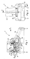
- a part of a battery-powered electric hand tool device 1 with a handle 3 of a machine housing part 5 and with a cover 7 of a battery housing part 9 can be seen.
- Cover 7 of the battery housing part 9 and handle 3 of the machine housing part 5 are connected to one another via a locking device 11.
- the battery housing part 9 is pushed over a sliding seat receptacle 10 in an operating position at the lower end of the handle 3 on the handle 3.
- a locking element 13 of the locking device 11 arranged in the handle 3 engages in a recess 15 of the cover 7 of the battery housing part 9.
- the battery housing part 9 has on the side facing away from the handle 3 joining elements 17. About this it is possible to connect the lid 7 with a lower shell of the battery housing part 9, not shown.
- grooves 19 On the handle 3 facing side of the lid 7 of the battery case part 9 grooves 19 can be seen.
- the grooves 19 are open in a receiving direction 21 and inwardly towards the inside.
- the grooves 19 are arranged on both sides of the cover 7 of the battery housing part 9 so that they form the sliding seat receptacle 10 with webs or rails 23 of the handle 3 extending in the receiving direction 21.
- the already mentioned recess 15 of the cover 7 is located on the handle 3 facing the upper side of the battery housing part 9.
- the recess 15 is bounded by an inclined first side surface 25. This is so inclined to the receiving direction 21, that the locking element 13 presses the battery housing part 9 in the sliding seat receptacle 10 in the receiving direction 21 when the battery housing part 9 is in its operating position. The locking element 13 is then under bias against the inclined side surface 25 at.
- the locking device 11 has an actuating member 27.
- the actuator 27 protrudes with a pusher 29 from an opening 30 of the handle 3 to the outside.
- a flat portion 31 connects, which is substantially disc-shaped.
- This is followed in the direction of the locking element 13, an inclined portion 33 which is inclined with respect to the receiving direction 21 in a clockwise direction.
- This inclined portion 33 passes through an opening 45 in the locking element 13
- a contact surface 35 of the inclined portion 33 of the actuator 27 contacts a contact surface 37 of the locking element 13.
- the actuator 27 is guided in the interior of the handle 3 in the sliding direction 21 longitudinally displaceable.
- the actuator 27 has a recess 39 into which a leg spring 41 engages.
- the leg spring 41 is supported with one of its legs in a receptacle 43 of the handle 3, and with its other end on the pusher 29 of the actuator 27 from. In this case, the leg spring 41 exerts a force on the actuating member 27 in the receiving direction 21 so that the pusher 29 protrudes outward from the handle 3.
- the actuator 27 engages with its inclined portion 33 in an opening 45 of the locking element 13 so that the contact surface 35 of the inclined portion 33 is in contact with the contact surface 37 of the opening 45.
- the contact surface 47 of the opening 45 is inclined with respect to the receiving direction 21.
- the locking element 13 Transverse to the receiving direction 21, the locking element 13 has a region 49 which is disposed within a compression spring 51.
- the compression spring 51 is supported with one of its ends on the locking element 13 and from its other end in a receptacle 53 of the handle 3 from.
- the receptacle 53 and the receptacle 43 are integrally formed with the handle 3 in the embodiment shown in the figures. They are designed so that on the one hand the leg spring 41 and on the other hand the compression spring 51 provide a leading receptacle.
- the compression spring 51 acts on the locking element 13 in the locking direction.
- the locking element 13 has a projecting portion 55 whose surface is inclined to cooperate with the inclined first side surface 25 of the recess 15 of the battery housing part 9.
- the battery housing part 9 is pushed in the receiving direction 21 on the handle 3.
- the webs or Rails 23 of the handle 3 in the grooves 19 of the lid 7 of the battery housing part 9 a. Grooves 19 and rails 23 thereby form the sliding seat receptacle 10th
- the locking element 13 Under the action of the compression spring 51, the locking element 13 is always loaded in the locking direction.
- the battery housing part 9 is pressed in the receiving direction 21 in the sliding seat receptacle 10. The battery housing part 9 is thus locked in the handle 3 in an operating position.
- the actuator 27 is pressed against the receiving direction 21 manually.
- the inclined portion 33 of the actuating member 27 is pushed into the opening 45 of the locking element 13. Due to the inclination of the inclined contact surfaces 35 and 37 while the locking element 13 is displaced in the unlocking, so that it is released from the recess 15 of the battery housing part.
- the projecting portion 55 of the locking element 13 is moved out of the recess 15 of the lid 7 of the battery housing part 9.
Landscapes
- Engineering & Computer Science (AREA)
- Life Sciences & Earth Sciences (AREA)
- Biophysics (AREA)
- Computer Hardware Design (AREA)
- Chemical & Material Sciences (AREA)
- Chemical Kinetics & Catalysis (AREA)
- Electrochemistry (AREA)
- General Chemical & Material Sciences (AREA)
- Mechanical Engineering (AREA)
- Battery Mounting, Suspending (AREA)
- Portable Power Tools In General (AREA)
- Power Steering Mechanism (AREA)
Priority Applications (4)
| Application Number | Priority Date | Filing Date | Title |
|---|---|---|---|
| DE502007001912T DE502007001912D1 (de) | 2007-06-06 | 2007-06-06 | Akkubetriebenes Elektrohandwerkzeuggerät |
| EP07011089A EP2000266B1 (fr) | 2007-06-06 | 2007-06-06 | Machine-outil electrique motorisé à batterie |
| ES07011089T ES2333269T3 (es) | 2007-06-06 | 2007-06-06 | Maquina herramienta electrica manual alimentada por bateria. |
| AT07011089T ATE447466T1 (de) | 2007-06-06 | 2007-06-06 | Akkubetriebenes elektrohandwerkzeuggerät |
Applications Claiming Priority (1)
| Application Number | Priority Date | Filing Date | Title |
|---|---|---|---|
| EP07011089A EP2000266B1 (fr) | 2007-06-06 | 2007-06-06 | Machine-outil electrique motorisé à batterie |
Publications (2)
| Publication Number | Publication Date |
|---|---|
| EP2000266A1 true EP2000266A1 (fr) | 2008-12-10 |
| EP2000266B1 EP2000266B1 (fr) | 2009-11-04 |
Family
ID=38222096
Family Applications (1)
| Application Number | Title | Priority Date | Filing Date |
|---|---|---|---|
| EP07011089A Not-in-force EP2000266B1 (fr) | 2007-06-06 | 2007-06-06 | Machine-outil electrique motorisé à batterie |
Country Status (4)
| Country | Link |
|---|---|
| EP (1) | EP2000266B1 (fr) |
| AT (1) | ATE447466T1 (fr) |
| DE (1) | DE502007001912D1 (fr) |
| ES (1) | ES2333269T3 (fr) |
Cited By (2)
| Publication number | Priority date | Publication date | Assignee | Title |
|---|---|---|---|---|
| US11539163B2 (en) | 2019-03-12 | 2022-12-27 | Milwaukee Electric Tool Corporation | Electric device including a housing for receiving a battery pack and a latching mechanism |
| DE102023136656A1 (de) * | 2023-12-22 | 2025-06-26 | Festool Gmbh | Werkzeugmaschine, insbesondere Handwerkzeugmaschine |
Families Citing this family (1)
| Publication number | Priority date | Publication date | Assignee | Title |
|---|---|---|---|---|
| EP2875910B1 (fr) | 2013-10-15 | 2016-06-08 | Sparky Eltos Ad | Dispositif destiné à verrouiller des batteries d'un outil électrique |
Citations (4)
| Publication number | Priority date | Publication date | Assignee | Title |
|---|---|---|---|---|
| GB2303018A (en) * | 1995-06-30 | 1997-02-05 | Nec Corp | Battery case mounting mechanism incorporates electrical contacts |
| EP1463274A1 (fr) * | 2003-03-25 | 2004-09-29 | LG Electronics Inc. | Mécanisme de verrouillage |
| EP1683608A1 (fr) * | 2005-01-24 | 2006-07-26 | Techtronic Industries Co., Ltd. | Mécanisme d'éjection de batterie du type coulisseau |
| EP1744386A2 (fr) * | 2001-11-09 | 2007-01-17 | Milwaukee Electric Tool Corporation | Dispositif combiné comprenant un radio, dispositif audio et un chargeur de batterie. |
-
2007
- 2007-06-06 ES ES07011089T patent/ES2333269T3/es active Active
- 2007-06-06 DE DE502007001912T patent/DE502007001912D1/de active Active
- 2007-06-06 EP EP07011089A patent/EP2000266B1/fr not_active Not-in-force
- 2007-06-06 AT AT07011089T patent/ATE447466T1/de active
Patent Citations (4)
| Publication number | Priority date | Publication date | Assignee | Title |
|---|---|---|---|---|
| GB2303018A (en) * | 1995-06-30 | 1997-02-05 | Nec Corp | Battery case mounting mechanism incorporates electrical contacts |
| EP1744386A2 (fr) * | 2001-11-09 | 2007-01-17 | Milwaukee Electric Tool Corporation | Dispositif combiné comprenant un radio, dispositif audio et un chargeur de batterie. |
| EP1463274A1 (fr) * | 2003-03-25 | 2004-09-29 | LG Electronics Inc. | Mécanisme de verrouillage |
| EP1683608A1 (fr) * | 2005-01-24 | 2006-07-26 | Techtronic Industries Co., Ltd. | Mécanisme d'éjection de batterie du type coulisseau |
Cited By (3)
| Publication number | Priority date | Publication date | Assignee | Title |
|---|---|---|---|---|
| US11539163B2 (en) | 2019-03-12 | 2022-12-27 | Milwaukee Electric Tool Corporation | Electric device including a housing for receiving a battery pack and a latching mechanism |
| US12347968B2 (en) | 2019-03-12 | 2025-07-01 | Milwaukee Electric Tool Corporation | Locking mechanism for a battery pack on a portable electric device |
| DE102023136656A1 (de) * | 2023-12-22 | 2025-06-26 | Festool Gmbh | Werkzeugmaschine, insbesondere Handwerkzeugmaschine |
Also Published As
| Publication number | Publication date |
|---|---|
| ATE447466T1 (de) | 2009-11-15 |
| DE502007001912D1 (de) | 2009-12-17 |
| EP2000266B1 (fr) | 2009-11-04 |
| ES2333269T3 (es) | 2010-02-18 |
Similar Documents
| Publication | Publication Date | Title |
|---|---|---|
| DE2355497C2 (de) | Verschluß für Sicherheitsgurte | |
| EP1491295B1 (fr) | Boulon pour la fixation d'un élément d'outil sur un outil de sertissage hydraulique | |
| EP2279317B1 (fr) | Serrure de porte de véhicule à levier de déblocage intérieur | |
| DE102006009976A1 (de) | Radialverstellmechanismus zur Anwendung in einer Fahrzeugsitzbaugruppe | |
| EP2245963B1 (fr) | Élément constitué d'une première et seconde pièce de meuble étant connectées et ajustables par un dispositif de connexion | |
| DE102008050477A1 (de) | Kochgeschirr mit abnehmbarem Griff- oder Stielelement | |
| EP2000266B1 (fr) | Machine-outil electrique motorisé à batterie | |
| WO2012104056A1 (fr) | Appareil médical | |
| DE19928729B4 (de) | Fenstergriffschloß | |
| EP1528194A1 (fr) | Ferrure, notamment ferrure de fenêtre | |
| DE202009007599U1 (de) | Akkubetriebenes Elektrohandwerkzeuggerät | |
| EP2056318B1 (fr) | Interrupteur, notamment interrupteur de lève-vitre | |
| DE102019115157B4 (de) | Schaltervorrichtung für ein Gargerät mit einem durch eine Tür verschließbaren Garraum und Gargerät | |
| EP1249570A1 (fr) | Dispositif de fermeture | |
| EP1174892A2 (fr) | Dispositif de verrouillage mécanique pour les positions marche et arrêt d'un interrupteur à bouton-poussoir | |
| EP2354386B1 (fr) | Dispositif de pêne retour de sangle à carter | |
| EP3686908A1 (fr) | Appareil d'installation électrique pourvu de douille de socle | |
| EP3819422B1 (fr) | Articulation et séchoir à linge doté d'une telle articulation | |
| DE3417726C2 (fr) | ||
| AT389915B (de) | Schloss mit selbstspannender nuss | |
| DE102008018667A1 (de) | Verriegelungsvorrichtung | |
| EP2808847B1 (fr) | Clé électronique | |
| DE202012104751U1 (de) | Schraubenschlüssel | |
| DE102005007225B4 (de) | Deckel für Sicherungs-Lasttrennschalter mit verstellbarem Griff | |
| DE4331091C1 (de) | Handbetätigter Schalter mit einer Verriegelung |
Legal Events
| Date | Code | Title | Description |
|---|---|---|---|
| PUAI | Public reference made under article 153(3) epc to a published international application that has entered the european phase |
Free format text: ORIGINAL CODE: 0009012 |
|
| AK | Designated contracting states |
Kind code of ref document: A1 Designated state(s): AT BE BG CH CY CZ DE DK EE ES FI FR GB GR HU IE IS IT LI LT LU LV MC MT NL PL PT RO SE SI SK TR |
|
| AX | Request for extension of the european patent |
Extension state: AL BA HR MK RS |
|
| 17P | Request for examination filed |
Effective date: 20090319 |
|
| RIN1 | Information on inventor provided before grant (corrected) |
Inventor name: CONG, PHAM Inventor name: SCHWARZ, STEFAN, DIPL.ING.(FH) Inventor name: DAESCHLER, ARTTU Inventor name: FISCHER, WERNER |
|
| GRAP | Despatch of communication of intention to grant a patent |
Free format text: ORIGINAL CODE: EPIDOSNIGR1 |
|
| AKX | Designation fees paid |
Designated state(s): AT BE BG CH CY CZ DE DK EE ES FI FR GB GR HU IE IS IT LI LT LU LV MC MT NL PL PT RO SE SI SK TR |
|
| GRAS | Grant fee paid |
Free format text: ORIGINAL CODE: EPIDOSNIGR3 |
|
| GRAA | (expected) grant |
Free format text: ORIGINAL CODE: 0009210 |
|
| AK | Designated contracting states |
Kind code of ref document: B1 Designated state(s): AT BE BG CH CY CZ DE DK EE ES FI FR GB GR HU IE IS IT LI LT LU LV MC MT NL PL PT RO SE SI SK TR |
|
| REG | Reference to a national code |
Ref country code: GB Ref legal event code: FG4D Free format text: NOT ENGLISH |
|
| REG | Reference to a national code |
Ref country code: CH Ref legal event code: EP |
|
| REG | Reference to a national code |
Ref country code: IE Ref legal event code: FG4D |
|
| REF | Corresponds to: |
Ref document number: 502007001912 Country of ref document: DE Date of ref document: 20091217 Kind code of ref document: P |
|
| REG | Reference to a national code |
Ref country code: ES Ref legal event code: FG2A Ref document number: 2333269 Country of ref document: ES Kind code of ref document: T3 |
|
| LTIE | Lt: invalidation of european patent or patent extension |
Effective date: 20091104 |
|
| PG25 | Lapsed in a contracting state [announced via postgrant information from national office to epo] |
Ref country code: PT Free format text: LAPSE BECAUSE OF FAILURE TO SUBMIT A TRANSLATION OF THE DESCRIPTION OR TO PAY THE FEE WITHIN THE PRESCRIBED TIME-LIMIT Effective date: 20100304 Ref country code: SE Free format text: LAPSE BECAUSE OF FAILURE TO SUBMIT A TRANSLATION OF THE DESCRIPTION OR TO PAY THE FEE WITHIN THE PRESCRIBED TIME-LIMIT Effective date: 20091104 Ref country code: LT Free format text: LAPSE BECAUSE OF FAILURE TO SUBMIT A TRANSLATION OF THE DESCRIPTION OR TO PAY THE FEE WITHIN THE PRESCRIBED TIME-LIMIT Effective date: 20091104 Ref country code: IS Free format text: LAPSE BECAUSE OF FAILURE TO SUBMIT A TRANSLATION OF THE DESCRIPTION OR TO PAY THE FEE WITHIN THE PRESCRIBED TIME-LIMIT Effective date: 20100304 Ref country code: FI Free format text: LAPSE BECAUSE OF FAILURE TO SUBMIT A TRANSLATION OF THE DESCRIPTION OR TO PAY THE FEE WITHIN THE PRESCRIBED TIME-LIMIT Effective date: 20091104 |
|
| REG | Reference to a national code |
Ref country code: IE Ref legal event code: FD4D |
|
| PG25 | Lapsed in a contracting state [announced via postgrant information from national office to epo] |
Ref country code: CY Free format text: LAPSE BECAUSE OF FAILURE TO SUBMIT A TRANSLATION OF THE DESCRIPTION OR TO PAY THE FEE WITHIN THE PRESCRIBED TIME-LIMIT Effective date: 20091104 Ref country code: SI Free format text: LAPSE BECAUSE OF FAILURE TO SUBMIT A TRANSLATION OF THE DESCRIPTION OR TO PAY THE FEE WITHIN THE PRESCRIBED TIME-LIMIT Effective date: 20091104 Ref country code: LV Free format text: LAPSE BECAUSE OF FAILURE TO SUBMIT A TRANSLATION OF THE DESCRIPTION OR TO PAY THE FEE WITHIN THE PRESCRIBED TIME-LIMIT Effective date: 20091104 Ref country code: PL Free format text: LAPSE BECAUSE OF FAILURE TO SUBMIT A TRANSLATION OF THE DESCRIPTION OR TO PAY THE FEE WITHIN THE PRESCRIBED TIME-LIMIT Effective date: 20091104 |
|
| PG25 | Lapsed in a contracting state [announced via postgrant information from national office to epo] |
Ref country code: BG Free format text: LAPSE BECAUSE OF FAILURE TO SUBMIT A TRANSLATION OF THE DESCRIPTION OR TO PAY THE FEE WITHIN THE PRESCRIBED TIME-LIMIT Effective date: 20100204 Ref country code: EE Free format text: LAPSE BECAUSE OF FAILURE TO SUBMIT A TRANSLATION OF THE DESCRIPTION OR TO PAY THE FEE WITHIN THE PRESCRIBED TIME-LIMIT Effective date: 20091104 Ref country code: RO Free format text: LAPSE BECAUSE OF FAILURE TO SUBMIT A TRANSLATION OF THE DESCRIPTION OR TO PAY THE FEE WITHIN THE PRESCRIBED TIME-LIMIT Effective date: 20091104 Ref country code: IE Free format text: LAPSE BECAUSE OF FAILURE TO SUBMIT A TRANSLATION OF THE DESCRIPTION OR TO PAY THE FEE WITHIN THE PRESCRIBED TIME-LIMIT Effective date: 20091104 Ref country code: DK Free format text: LAPSE BECAUSE OF FAILURE TO SUBMIT A TRANSLATION OF THE DESCRIPTION OR TO PAY THE FEE WITHIN THE PRESCRIBED TIME-LIMIT Effective date: 20091104 |
|
| PG25 | Lapsed in a contracting state [announced via postgrant information from national office to epo] |
Ref country code: SK Free format text: LAPSE BECAUSE OF FAILURE TO SUBMIT A TRANSLATION OF THE DESCRIPTION OR TO PAY THE FEE WITHIN THE PRESCRIBED TIME-LIMIT Effective date: 20091104 Ref country code: CZ Free format text: LAPSE BECAUSE OF FAILURE TO SUBMIT A TRANSLATION OF THE DESCRIPTION OR TO PAY THE FEE WITHIN THE PRESCRIBED TIME-LIMIT Effective date: 20091104 |
|
| PLBE | No opposition filed within time limit |
Free format text: ORIGINAL CODE: 0009261 |
|
| STAA | Information on the status of an ep patent application or granted ep patent |
Free format text: STATUS: NO OPPOSITION FILED WITHIN TIME LIMIT |
|
| 26N | No opposition filed |
Effective date: 20100805 |
|
| PG25 | Lapsed in a contracting state [announced via postgrant information from national office to epo] |
Ref country code: GR Free format text: LAPSE BECAUSE OF FAILURE TO SUBMIT A TRANSLATION OF THE DESCRIPTION OR TO PAY THE FEE WITHIN THE PRESCRIBED TIME-LIMIT Effective date: 20100205 |
|
| BERE | Be: lapsed |
Owner name: METABOWERKE G.M.B.H. Effective date: 20100630 |
|
| REG | Reference to a national code |
Ref country code: NL Ref legal event code: V1 Effective date: 20110101 |
|
| PG25 | Lapsed in a contracting state [announced via postgrant information from national office to epo] |
Ref country code: MC Free format text: LAPSE BECAUSE OF NON-PAYMENT OF DUE FEES Effective date: 20100630 |
|
| PG25 | Lapsed in a contracting state [announced via postgrant information from national office to epo] |
Ref country code: MT Free format text: LAPSE BECAUSE OF FAILURE TO SUBMIT A TRANSLATION OF THE DESCRIPTION OR TO PAY THE FEE WITHIN THE PRESCRIBED TIME-LIMIT Effective date: 20091104 |
|
| PG25 | Lapsed in a contracting state [announced via postgrant information from national office to epo] |
Ref country code: NL Free format text: LAPSE BECAUSE OF NON-PAYMENT OF DUE FEES Effective date: 20110101 |
|
| PG25 | Lapsed in a contracting state [announced via postgrant information from national office to epo] |
Ref country code: BE Free format text: LAPSE BECAUSE OF NON-PAYMENT OF DUE FEES Effective date: 20100630 |
|
| REG | Reference to a national code |
Ref country code: ES Ref legal event code: FD2A Effective date: 20110715 |
|
| PG25 | Lapsed in a contracting state [announced via postgrant information from national office to epo] |
Ref country code: ES Free format text: LAPSE BECAUSE OF NON-PAYMENT OF DUE FEES Effective date: 20110705 |
|
| PG25 | Lapsed in a contracting state [announced via postgrant information from national office to epo] |
Ref country code: ES Free format text: LAPSE BECAUSE OF NON-PAYMENT OF DUE FEES Effective date: 20100607 |
|
| PGFP | Annual fee paid to national office [announced via postgrant information from national office to epo] |
Ref country code: CH Payment date: 20120622 Year of fee payment: 6 |
|
| PG25 | Lapsed in a contracting state [announced via postgrant information from national office to epo] |
Ref country code: HU Free format text: LAPSE BECAUSE OF FAILURE TO SUBMIT A TRANSLATION OF THE DESCRIPTION OR TO PAY THE FEE WITHIN THE PRESCRIBED TIME-LIMIT Effective date: 20100505 Ref country code: LU Free format text: LAPSE BECAUSE OF NON-PAYMENT OF DUE FEES Effective date: 20100606 |
|
| PG25 | Lapsed in a contracting state [announced via postgrant information from national office to epo] |
Ref country code: TR Free format text: LAPSE BECAUSE OF FAILURE TO SUBMIT A TRANSLATION OF THE DESCRIPTION OR TO PAY THE FEE WITHIN THE PRESCRIBED TIME-LIMIT Effective date: 20091104 |
|
| PGFP | Annual fee paid to national office [announced via postgrant information from national office to epo] |
Ref country code: AT Payment date: 20120620 Year of fee payment: 6 |
|
| REG | Reference to a national code |
Ref country code: CH Ref legal event code: PL |
|
| REG | Reference to a national code |
Ref country code: AT Ref legal event code: MM01 Ref document number: 447466 Country of ref document: AT Kind code of ref document: T Effective date: 20130606 |
|
| PG25 | Lapsed in a contracting state [announced via postgrant information from national office to epo] |
Ref country code: LI Free format text: LAPSE BECAUSE OF NON-PAYMENT OF DUE FEES Effective date: 20130630 Ref country code: CH Free format text: LAPSE BECAUSE OF NON-PAYMENT OF DUE FEES Effective date: 20130630 |
|
| PG25 | Lapsed in a contracting state [announced via postgrant information from national office to epo] |
Ref country code: AT Free format text: LAPSE BECAUSE OF NON-PAYMENT OF DUE FEES Effective date: 20130606 |
|
| REG | Reference to a national code |
Ref country code: DE Ref legal event code: R082 Ref document number: 502007001912 Country of ref document: DE Representative=s name: LORENZ & KOLLEGEN PATENTANWAELTE PARTNERSCHAFT, DE |
|
| REG | Reference to a national code |
Ref country code: FR Ref legal event code: PLFP Year of fee payment: 10 |
|
| REG | Reference to a national code |
Ref country code: FR Ref legal event code: PLFP Year of fee payment: 11 |
|
| REG | Reference to a national code |
Ref country code: FR Ref legal event code: PLFP Year of fee payment: 12 |
|
| PGFP | Annual fee paid to national office [announced via postgrant information from national office to epo] |
Ref country code: IT Payment date: 20210630 Year of fee payment: 15 Ref country code: FR Payment date: 20210621 Year of fee payment: 15 |
|
| PGFP | Annual fee paid to national office [announced via postgrant information from national office to epo] |
Ref country code: GB Payment date: 20210623 Year of fee payment: 15 |
|
| GBPC | Gb: european patent ceased through non-payment of renewal fee |
Effective date: 20220606 |
|
| PG25 | Lapsed in a contracting state [announced via postgrant information from national office to epo] |
Ref country code: FR Free format text: LAPSE BECAUSE OF NON-PAYMENT OF DUE FEES Effective date: 20220630 |
|
| PG25 | Lapsed in a contracting state [announced via postgrant information from national office to epo] |
Ref country code: GB Free format text: LAPSE BECAUSE OF NON-PAYMENT OF DUE FEES Effective date: 20220606 |
|
| PGFP | Annual fee paid to national office [announced via postgrant information from national office to epo] |
Ref country code: DE Payment date: 20230620 Year of fee payment: 17 |
|
| REG | Reference to a national code |
Ref country code: DE Ref legal event code: R119 Ref document number: 502007001912 Country of ref document: DE |
|
| PG25 | Lapsed in a contracting state [announced via postgrant information from national office to epo] |
Ref country code: DE Free format text: LAPSE BECAUSE OF NON-PAYMENT OF DUE FEES Effective date: 20250101 |
|
| PG25 | Lapsed in a contracting state [announced via postgrant information from national office to epo] |
Ref country code: IT Free format text: LAPSE BECAUSE OF NON-PAYMENT OF DUE FEES Effective date: 20220606 |