EP2000314A1 - Appareil d'enregistrement à jet d'encre - Google Patents
Appareil d'enregistrement à jet d'encre Download PDFInfo
- Publication number
- EP2000314A1 EP2000314A1 EP08009739A EP08009739A EP2000314A1 EP 2000314 A1 EP2000314 A1 EP 2000314A1 EP 08009739 A EP08009739 A EP 08009739A EP 08009739 A EP08009739 A EP 08009739A EP 2000314 A1 EP2000314 A1 EP 2000314A1
- Authority
- EP
- European Patent Office
- Prior art keywords
- recording medium
- recording
- inkjet
- scanning direction
- color
- Prior art date
- Legal status (The legal status is an assumption and is not a legal conclusion. Google has not performed a legal analysis and makes no representation as to the accuracy of the status listed.)
- Withdrawn
Links
Images


Classifications
-
- B—PERFORMING OPERATIONS; TRANSPORTING
- B41—PRINTING; LINING MACHINES; TYPEWRITERS; STAMPS
- B41J—TYPEWRITERS; SELECTIVE PRINTING MECHANISMS, i.e. MECHANISMS PRINTING OTHERWISE THAN FROM A FORME; CORRECTION OF TYPOGRAPHICAL ERRORS
- B41J11/00—Devices or arrangements of selective printing mechanisms, e.g. ink-jet printers or thermal printers, for supporting or handling copy material in sheet or web form
- B41J11/0015—Devices or arrangements of selective printing mechanisms, e.g. ink-jet printers or thermal printers, for supporting or handling copy material in sheet or web form for treating before, during or after printing or for uniform coating or laminating the copy material before or after printing
Definitions
- This invention relates to an inkjet recording apparatus for recording images on a recording medium by moving the recording medium in a secondary scanning direction with a recording medium transport mechanism, and moving a recording head in a primary scanning direction perpendicular to the secondary scanning direction.
- a known inkjet recording apparatus is described in Japanese Unexamined Patent Publication No. 2006-51773 , for example.
- a background-color ink e.g. white ink
- color inks such as Y, M, C and K.
- background-color inkjet heads for discharging background-color ink must be arranged at opposite sides, in the primary scanning direction or secondary scanning direction, of a plurality of color inkjet heads arranged in the primary scanning direction for discharging the different color inks.
- the object of this invention is to provide an inkjet recording apparatus, simple in construction and entailing no increase in the cost of the apparatus, and yet capable of performing both the process for printing in background-color ink first, and then printing in color inks, and the process for printing in color inks first, and then printing in background-color ink, without lowering productivity.
- an inkjet recording apparatus for recording images on a recording medium by moving the recording medium in a secondary scanning direction with a recording medium transport mechanism, and moving a recording head in a primary scanning direction perpendicular to the secondary scanning direction
- the recording head includes a plurality of color inkjet heads arranged in an array in the primary scanning direction for discharging different color inks, and a background-color inkjet head for discharging background-color ink, the background-color inkjet head being disposed in a position different from the array of the color inkjet heads with respect to the secondary scanning direction, and adjacent one of a forward end and a rearward end of the array
- the recording medium transport mechanism is constructed to transport the recording medium selectively in a first direction in which the background-color inkjet head is located upstream with respect to the secondary scanning direction, and in a second direction in which the color inkjet heads are located upstream with respect to the secondary scanning direction.
- Such an inkjet recording apparatus is simple in construction entailing no increase in the cost of the apparatus, and yet is capable of selectively performing both a process for printing in background-color ink first, and then printing in color inks, and a process for printing in color inks first, and then printing in background-color ink.
- the inkjet recording apparatus can transport the recording medium effectively whether it is a long sheet-like material or a hard, plate-like material.
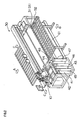
- Fig. 1 is a schematic front view of an inkjet recording apparatus according to this invention
- Fig. 2 is a perspective view of the apparatus.
- This inkjet recording apparatus records images on an elongate recording medium S by moving the recording medium S in a secondary scanning direction indicated by an arrow A or B in Figs. 1 and 2 , and moving a recording head 10 with a recording head moving mechanism 30 in a primary scanning direction, indicated by arrows C in Fig. 2 , perpendicular to the secondary scanning direction.
- a porous endless belt 51 is wound around a pair of rollers 53 and 54.
- the endless belt 51 defines an upper running portion and a lower running portion.
- the surface of the upper running portion which contacts the recording medium S can hold the recording medium S by suction applied by a suction mechanism not shown.
- At least one of the rollers 53 and 54 is connected to a reversible motor, to be able to move the upper running portion of the endless belt 51 in both the direction of arrow A (first direction) and the direction of arrow B (second direction).
- the recording medium S is unwound from a first roller 61 rotatable by drive of a motor 65, to move through a tension adjusting mechanism 63 and onward as held by suction on the upper running portion of the porous endless belt 51.
- the recording medium S moves further through a tension adjusting mechanism 64 to be wound on a second roller 62 rotatable by drive of a motor 66.
- the recording medium S moves in the direction of arrow A (first direction) shown in Figs. 1 and 2 .
- the recording medium S is unwound from the second roller 62, to move through the tension adjusting mechanism 64 and onward as held by suction on the upper running portion of the porous endless belt 51.
- the recording medium S moves further through the tension adjusting mechanism 63 to be wound on the first roller 61.
- the recording medium S moves in the direction of arrow B (second direction) shown in Figs. 1 and 2 .
- first roller 61, second roller 62 and endless belt 51 constitute a recording medium transport mechanism for transporting the recording medium S in both the first direction and second direction.
- This inkjet recording apparatus can record also on a hard, plate-like recording medium instead of the elongate, soft recording medium S.
- an auxiliary table 52 shown in Fig. 2 is used in holding the hard, plate-like recording medium by suction on the endless belt 51.
- the auxiliary table 52 is adjusted to have an upper surface thereof located on the same plane as the upper running portion of the endless belt 51. Since at least one of the rollers 53 and 54 is connected to the reversible motor as noted above, the drive of this motor may be utilized to move the hard, plate-like recording medium in the secondary scanning direction as held by suction on the endless belt 51.
- This inkjet recording apparatus carries out multicolor printing using yellow, magenta, cyan, black, light cyan, light magenta and white inks.
- this inkjet recording apparatus includes a yellow ink tank 44, magenta ink tank 43, cyan ink tank 42, black ink tank 41, light cyan ink tank 46, light magenta ink tank 45 white ink tank 47, and cleaning solution tank 48.
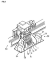
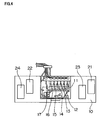
- Fig. 3 is a perspective view of the recording head 10, and Fig. 4 is a plan view thereof.
- Fig. 5 is an explanatory view schematically showing an arrangement of inkjet heads 11, 12, 13, 14, 15, 16 and 17.
- This recording head 10 includes an inkjet head 11 for light magenta ink, an inkjet head 12 for yellow ink, an inkjet head 13 for cyan ink, an inkjet head 14 for black ink, an inkjet head 15 for magenta ink, an inkjet head 16 for light cyan ink and an inkjet head 17 for white ink.
- inkjet head 11 for light magenta ink inkjet head 12 for yellow ink, inkjet head 13 for cyan ink, inkjet head 14 for black ink, inkjet head 15 for magenta ink and inkjet head 16 for light cyan are arranged in the primary scanning direction (i.e. the direction of arrow C shown in Fig. 5 ).
- the inkjet head 17 for white ink is disposed in a position different from the inkjet heads 11, 12, 13, 14, 15 and 16 with respect to the secondary scanning direction (i.e. the direction of arrow A or B shown in Fig. 5 ), and either forward or rearward of the inkjet heads 11, 12, 13, 14, 15 and 16 with respect to the primary scanning direction. That is, the inkjet heads 11, 12, 13, 14, 15 and 16, and the inkjet head 17 for white ink, are staggered from each other in the secondary scanning direction.
- a pair of UV lamps 21 and 22 are arranged at opposite sides of the group of inkjet heads 11, 12, 13, 14, 15 and 16 (i.e. in the same positions as the inkjet heads 11, 12, 13, 14, 15 and 16 with respect to the secondary scanning direction) for drying the color inks discharged from the inkjet heads 11, 12, 13, 14, 15 and 16.
- Another pair of UV lamps 23 and 24 are arranged at opposite sides of the inkjet head 17 for white ink (i.e. the same position as the inkjet head 17 for white ink with respect to the secondary scanning direction) for drying the white ink discharged from the inkjet head 17.
- Fig. 6 is an explanatory view illustrating the image recording operations.
- Fig. 6 depicts the elongate recording medium S as being in sheet form.
- this inkjet recording apparatus When this inkjet recording apparatus records an image in the pre-white process in which the image is printed in the white ink first and then in the color inks, the inks are discharged from the inkjet heads 11, 12, 13, 14, 15, 16 and 17 in response to image signals while moving the recording head 10 in the primary scanning direction.
- the recording head 10 When the recording head 10 has moved to a stroke end in the primary scanning direction, the recording medium S is moved in the direction of arrow A shown in Figs. 1 , 2 , 5 and 6 (i.e. in the first direction of the secondary scanning direction), by a distance corresponding to one scan of the recording head 10.
- the recording medium S is unwound from the first roller 61, moved as held by suction on the porous endless belt 51, and then wound on the second roller 62.
- the recording head 10 is moved in the direction opposite to the above image-recording direction, back to the opposite stroke end in the primary scanning direction.
- the image is recorded on the recording medium S by the inkjet head 17 for white ink and by the plurality of inkjet heads 11, 12, 13, 14, 15 and 16 for color inks.
- the recording medium S is transported in the first direction in which the inkjet head 17 for white ink is located upstream, with respect to the secondary scanning direction, of the plurality of inkjet heads 11, 12, 13, 14, 15 and 16 for color inks.
- printing is done in the pre-white process in which the image is printed in the white ink first and then in the color inks.
- this inkjet recording apparatus records an image in the post-white process in which the image is printed in the color inks first and then in the white ink, again, the inks are discharged from the inkjet heads 11, 12, 13, 14, 15, 16 and 17 in response to image signals while moving the recording head 10 in the primary scanning direction.
- the recording head 10 has moved to a stroke end in the primary scanning direction, the recording medium S is moved in the direction of arrow B shown in Figs. 1 , 2 , 5 and 6 (i.e. in the second direction), by a distance corresponding to one scan of the recording head 10.
- the recording medium S is unwound from the second roller 62, moved as held by suction on the porous endless belt 51, and then wound on the first roller 61.
- the recording head 10 is moved in the direction opposite to the above image-recording direction, back to the opposite stroke end in the primary scanning direction.
- the image is recorded on the recording medium S by the inkjet head 17 for white ink and by the plurality of inkjet heads 11, 12, 13, 14, 15 and 16 for color inks.
- the recording medium S is transported in the second direction in which the plurality of inkjet heads 11, 12, 13, 14, 15 and 16 for color inks become upstream, with respect to the secondary scanning direction, of the inkjet head 17 for white ink.
- printing is done in the post-white process in which the image is printed in the color inks first and then in the white ink.
- an image is recorded only when the recording head 10 moves in one direction from one end to the other end, and not when the recording head 10 moves in the opposite direction. Instead, the image may be recorded all through the reciprocating movement of the recording head 10.
- This invention is applicable also where the moving distance in the direction of arrow A or B of the recording medium S is set to what is the distance corresponding to one scan divided by an integer. Such a setting may be made in order to increase ink quantity or improve resolution.
- a recording medium may be coated all over with a liquid such as varnish for improving ink absorbency of the recording medium, or an agent for improving durability of the recording medium.
- a liquid such as varnish for improving ink absorbency of the recording medium, or an agent for improving durability of the recording medium.
- This invention is applicable also where the recording medium is coated with such a liquid before or after image-recording inks are applied to the recording medium.
Landscapes
- Ink Jet (AREA)
Applications Claiming Priority (1)
| Application Number | Priority Date | Filing Date | Title |
|---|---|---|---|
| JP2007148147A JP2008296548A (ja) | 2007-06-04 | 2007-06-04 | インクジェット記録装置 |
Publications (1)
| Publication Number | Publication Date |
|---|---|
| EP2000314A1 true EP2000314A1 (fr) | 2008-12-10 |
Family
ID=39615718
Family Applications (1)
| Application Number | Title | Priority Date | Filing Date |
|---|---|---|---|
| EP08009739A Withdrawn EP2000314A1 (fr) | 2007-06-04 | 2008-05-28 | Appareil d'enregistrement à jet d'encre |
Country Status (3)
| Country | Link |
|---|---|
| US (1) | US20080297581A1 (fr) |
| EP (1) | EP2000314A1 (fr) |
| JP (1) | JP2008296548A (fr) |
Families Citing this family (1)
| Publication number | Priority date | Publication date | Assignee | Title |
|---|---|---|---|---|
| CN102529359B (zh) * | 2010-12-14 | 2014-11-12 | 精工爱普生株式会社 | 流体喷射装置和流体喷射方法 |
Citations (3)
| Publication number | Priority date | Publication date | Assignee | Title |
|---|---|---|---|---|
| EP1155870A2 (fr) * | 2000-05-16 | 2001-11-21 | Hewlett-Packard Company | Amélioration par surimpression de la résistance à l'eau d'images imprimées par jet d'encre |
| JP2006051773A (ja) | 2004-08-16 | 2006-02-23 | Konica Minolta Medical & Graphic Inc | インクジェット記録装置 |
| EP1754610A1 (fr) * | 2005-08-16 | 2007-02-21 | Mimaki Engineering Co., Ltd. | Tête à jet d'encre, imprimante l'utilisant et pocédé d'impression |
Family Cites Families (1)
| Publication number | Priority date | Publication date | Assignee | Title |
|---|---|---|---|---|
| JP2002103598A (ja) * | 2000-07-26 | 2002-04-09 | Olympus Optical Co Ltd | プリンタ |
-
2007
- 2007-06-04 JP JP2007148147A patent/JP2008296548A/ja active Pending
-
2008
- 2008-05-28 EP EP08009739A patent/EP2000314A1/fr not_active Withdrawn
- 2008-05-28 US US12/153,929 patent/US20080297581A1/en not_active Abandoned
Patent Citations (3)
| Publication number | Priority date | Publication date | Assignee | Title |
|---|---|---|---|---|
| EP1155870A2 (fr) * | 2000-05-16 | 2001-11-21 | Hewlett-Packard Company | Amélioration par surimpression de la résistance à l'eau d'images imprimées par jet d'encre |
| JP2006051773A (ja) | 2004-08-16 | 2006-02-23 | Konica Minolta Medical & Graphic Inc | インクジェット記録装置 |
| EP1754610A1 (fr) * | 2005-08-16 | 2007-02-21 | Mimaki Engineering Co., Ltd. | Tête à jet d'encre, imprimante l'utilisant et pocédé d'impression |
Also Published As
| Publication number | Publication date |
|---|---|
| JP2008296548A (ja) | 2008-12-11 |
| US20080297581A1 (en) | 2008-12-04 |
Similar Documents
| Publication | Publication Date | Title |
|---|---|---|
| JP4032360B2 (ja) | インクジェット記録装置及び吐出不良検出方法 | |
| JP3838251B2 (ja) | インクジェット記録装置及び吐出不良検出方法 | |
| JP2008036968A (ja) | 画像記録装置及び画像記録方法 | |
| US7614734B2 (en) | Inkjet recording apparatus and method | |
| JP2010076102A (ja) | 印字装置及び印字方法 | |
| US9248678B2 (en) | Information processing apparatus, and method for controlling image forming apparatus | |
| JP2006218860A (ja) | インクジェット記録装置 | |
| US7654635B2 (en) | Media print system | |
| JP2005096447A (ja) | インクジェット記録装置及び吐出不良検出方法 | |
| US7306311B2 (en) | Color ink deposition order determination method, and image forming method and apparatus | |
| US6899030B2 (en) | Lithographic plate imaging system to minimize plate misregistration for multicolor printing applications | |
| JP2004505801A (ja) | インクジェットプリンタ及びインクジェットプリンタ内で画材を印刷する方法 | |
| EP2000314A1 (fr) | Appareil d'enregistrement à jet d'encre | |
| US20090033694A1 (en) | Printer control system and method for artifact free and borderless printing | |
| JP2005088242A (ja) | 画像形成装置及び画像形成方法 | |
| JP2004188655A (ja) | インクジェットプリンタ | |
| WO2019058744A1 (fr) | Appareil d'impression et procédé d'impression | |
| JPWO2005097510A1 (ja) | 印刷装置 | |
| JP2007007899A (ja) | 印刷装置、印刷方法、および画像処理方法 | |
| JP2005096137A (ja) | 画像記録装置 | |
| WO2010061501A1 (fr) | Dispositif d’enregistrement d’une image par jet d’encre | |
| JP2002036530A (ja) | インクジェットプリンタ | |
| EP2767399B1 (fr) | Imprimante à jet d'encre | |
| JP7789011B2 (ja) | 画像形成装置及び印刷物の製造方法 | |
| US7252372B2 (en) | Liquid ejection apparatus and ejection control method |
Legal Events
| Date | Code | Title | Description |
|---|---|---|---|
| PUAI | Public reference made under article 153(3) epc to a published international application that has entered the european phase |
Free format text: ORIGINAL CODE: 0009012 |
|
| AK | Designated contracting states |
Kind code of ref document: A1 Designated state(s): AT BE BG CH CY CZ DE DK EE ES FI FR GB GR HR HU IE IS IT LI LT LU LV MC MT NL NO PL PT RO SE SI SK TR |
|
| AX | Request for extension of the european patent |
Extension state: AL BA MK RS |
|
| AKX | Designation fees paid |
Designated state(s): AT BE BG CH CY CZ DE DK EE ES FI FR GB GR HR HU IE IS IT LI LT LU LV MC MT NL NO PL PT RO SE SI SK TR |
|
| STAA | Information on the status of an ep patent application or granted ep patent |
Free format text: STATUS: THE APPLICATION IS DEEMED TO BE WITHDRAWN |
|
| 18D | Application deemed to be withdrawn |
Effective date: 20090611 |