EP1754610A1 - Tête à jet d'encre, imprimante l'utilisant et pocédé d'impression - Google Patents
Tête à jet d'encre, imprimante l'utilisant et pocédé d'impression Download PDFInfo
- Publication number
- EP1754610A1 EP1754610A1 EP06291309A EP06291309A EP1754610A1 EP 1754610 A1 EP1754610 A1 EP 1754610A1 EP 06291309 A EP06291309 A EP 06291309A EP 06291309 A EP06291309 A EP 06291309A EP 1754610 A1 EP1754610 A1 EP 1754610A1
- Authority
- EP
- European Patent Office
- Prior art keywords
- ground
- image
- ink
- medium
- color
- Prior art date
- Legal status (The legal status is an assumption and is not a legal conclusion. Google has not performed a legal analysis and makes no representation as to the accuracy of the status listed.)
- Granted
Links
Images


Classifications
-
- B—PERFORMING OPERATIONS; TRANSPORTING
- B41—PRINTING; LINING MACHINES; TYPEWRITERS; STAMPS
- B41J—TYPEWRITERS; SELECTIVE PRINTING MECHANISMS, i.e. MECHANISMS PRINTING OTHERWISE THAN FROM A FORME; CORRECTION OF TYPOGRAPHICAL ERRORS
- B41J3/00—Typewriters or selective printing or marking mechanisms characterised by the purpose for which they are constructed
- B41J3/407—Typewriters or selective printing or marking mechanisms characterised by the purpose for which they are constructed for marking on special material
-
- B—PERFORMING OPERATIONS; TRANSPORTING
- B41—PRINTING; LINING MACHINES; TYPEWRITERS; STAMPS
- B41J—TYPEWRITERS; SELECTIVE PRINTING MECHANISMS, i.e. MECHANISMS PRINTING OTHERWISE THAN FROM A FORME; CORRECTION OF TYPOGRAPHICAL ERRORS
- B41J11/00—Devices or arrangements of selective printing mechanisms, e.g. ink-jet printers or thermal printers, for supporting or handling copy material in sheet or web form
- B41J11/0015—Devices or arrangements of selective printing mechanisms, e.g. ink-jet printers or thermal printers, for supporting or handling copy material in sheet or web form for treating before, during or after printing or for uniform coating or laminating the copy material before or after printing
- B41J11/002—Curing or drying the ink on the copy materials, e.g. by heating or irradiating
-
- B—PERFORMING OPERATIONS; TRANSPORTING
- B41—PRINTING; LINING MACHINES; TYPEWRITERS; STAMPS
- B41J—TYPEWRITERS; SELECTIVE PRINTING MECHANISMS, i.e. MECHANISMS PRINTING OTHERWISE THAN FROM A FORME; CORRECTION OF TYPOGRAPHICAL ERRORS
- B41J2/00—Typewriters or selective printing mechanisms characterised by the printing or marking process for which they are designed
- B41J2/005—Typewriters or selective printing mechanisms characterised by the printing or marking process for which they are designed characterised by bringing liquid or particles selectively into contact with a printing material
- B41J2/01—Ink jet
- B41J2/21—Ink jet for multi-colour printing
- B41J2/2107—Ink jet for multi-colour printing characterised by the ink properties
- B41J2/2114—Ejecting specialized liquids, e.g. transparent or processing liquids
- B41J2/2117—Ejecting white liquids
-
- B—PERFORMING OPERATIONS; TRANSPORTING
- B41—PRINTING; LINING MACHINES; TYPEWRITERS; STAMPS
- B41J—TYPEWRITERS; SELECTIVE PRINTING MECHANISMS, i.e. MECHANISMS PRINTING OTHERWISE THAN FROM A FORME; CORRECTION OF TYPOGRAPHICAL ERRORS
- B41J11/00—Devices or arrangements of selective printing mechanisms, e.g. ink-jet printers or thermal printers, for supporting or handling copy material in sheet or web form
- B41J11/0015—Devices or arrangements of selective printing mechanisms, e.g. ink-jet printers or thermal printers, for supporting or handling copy material in sheet or web form for treating before, during or after printing or for uniform coating or laminating the copy material before or after printing
- B41J11/002—Curing or drying the ink on the copy materials, e.g. by heating or irradiating
- B41J11/0022—Curing or drying the ink on the copy materials, e.g. by heating or irradiating using convection means, e.g. by using a fan for blowing or sucking air
-
- B—PERFORMING OPERATIONS; TRANSPORTING
- B41—PRINTING; LINING MACHINES; TYPEWRITERS; STAMPS
- B41J—TYPEWRITERS; SELECTIVE PRINTING MECHANISMS, i.e. MECHANISMS PRINTING OTHERWISE THAN FROM A FORME; CORRECTION OF TYPOGRAPHICAL ERRORS
- B41J11/00—Devices or arrangements of selective printing mechanisms, e.g. ink-jet printers or thermal printers, for supporting or handling copy material in sheet or web form
- B41J11/0015—Devices or arrangements of selective printing mechanisms, e.g. ink-jet printers or thermal printers, for supporting or handling copy material in sheet or web form for treating before, during or after printing or for uniform coating or laminating the copy material before or after printing
- B41J11/002—Curing or drying the ink on the copy materials, e.g. by heating or irradiating
- B41J11/0024—Curing or drying the ink on the copy materials, e.g. by heating or irradiating using conduction means, e.g. by using a heated platen
Definitions
- the present invention relates to an ink-jet printer, a printing method and an ink-jet head.
- a color image for advertisement or the like is printed on such a medium as a transparent window glass or a transparent film by using an ink jet printer, it is impossible to directly print an image including the color image on the medium with ink droplets jetted from an ink jet head.
- a ground-color layer of, for example, white is first printed on the transparent medium with ink droplets for printing a ground-color layer jetted from an ink jet head.
- an image is printed over the front surface of the ground-color layer with ink droplets for printing an image jetted from another ink jet head. That is, printing is performed twice on the medium, with the ground-color layer and the image printed over each other.
- an image including a color image is printed on a transparent medium with the interposition of a ground-color layer, with the image printed over the ground-color layer.
- high-brightness intermediate colors of the image such as gray other than high-density colors such as red, blue, yellow, and black, for example, are disturbed by lights infiltrating in the image through the transparent medium and thus are not precisely expressed.
- a color image for advertisement or the like is printed on the back surface of a transparent medium
- an image is printed on the back surface of the medium with ink droplets for printing an image jetted from an ink jet head, and thereafter a ground-color layer of, for example, white is printed over the back surface of the image printed on the medium.
- the ground-color layer is printed over the back surface of the image including a color image, which has been printed on the medium.
- an image-fixing undercoat layer is printed on the medium with ink droplets for printing an undercoat layer jetted from an ink jet head, and thereafter an image is printed over the front surface of the undercoat layer with ink droplets for printing an image jetted from another ink jet head. That is, printing is performed twice on the medium, with the undercoat layer and the image printed over each other.
- an image is printed on such a medium as a metal plate or leather which is difficult to be stably fixed and printed with an image including a color image
- the image is printed on the medium with ink droplets for printing an image jetted from an ink jet head, and thereafter an overcoat layer is printed over the front surface of the image, which has been printed on the medium, with ink droplets for printing an overcoat layer jetted from another ink jet head.
- the overcoat layer covers and protects the front surface of the image to prevent the image from being scraped off from scrubbing or to prevent the image from having color fading under ultraviolet light.
- the ink jet printer includes a main ink jet head for jetting ink droplets for printing an image, and also a sub ink jet head for jetting ink droplets of, for example, white for printing a ground-color layer, with the two ink jet heads aligned with each other.
- a ground-color layer is printed on the front surface of the transparent medium with the ink droplets jetted from the sub ink jet head, and thereafter an image is printed over the front surface of the ground-color layer with the ink droplets jetted from the main ink jet head.
- an image is printed on the back surface of the transparent medium with the ink droplets jetted from the main ink jet head, and thereafter a ground-color layer is printed over the back surface of the image, which has been printed on the medium, with the ink droplets jetted from the sub ink jet head.
- an ink jet printer for printing an image on such a medium as a metal plate or leather which is difficult to be stably fixed and printed with an image including a color image, an ink jet printer includes a main ink jet head for jetting ink droplets for printing an image, and also a sub ink jet head for jetting ink droplets for printing an overcoat layer, with the two ink jet heads aligned with each other.
- an image is printed on the medium, which is difficult to be fixed with an image, with the ink droplets jetted from the main ink jet head, and thereafter an overcoat layer is printed over the front surface of the image, which has been printed on the medium, with the ink droplets jetted from the sub ink jet head.
- the overcoat layer covers and protects the front surface of the image to prevent the image from being scraped off from scrubbing.
- the ink jet printer which includes the sub ink j et head in addition to the main ink jet head, with the two ink j et heads aligned with each other, is used for printing an image on a transparent medium with the interposition of a ground-color layer, for printing an image on a medium which is difficult to be directly printed with an image, with the interposition of an undercoat layer, for printing a ground-color layer over the back surface of an image printed on the medium, and for printing an overcoat layer over the front surface of an image printed on the medium, as described above, the sub ink jet head which jets the ink droplets for printing a ground-color layer or an undercoat layer is caused to perform a reciprocating movement along a line Y parallel to the horizontal direction, and the medium is sent forth and moved on a platen by sending unit in the front direction of an X direction.
- the main ink jet head which jets the ink droplets for printing an image is caused to perform a reciprocating movement along the line Y corresponding to the horizontal direction, and the medium is sent forth and moved on the platen by the sending unit in the rear direction of the X direction.
- the ground-color layer, the undercoat layer, or the image is printed at a desired position on the medium.
- a part of the medium placed on the platen is nipped between a grid roller and a pinch roller of the sending unit, and the grid roller is rotated in the reverse direction.
- the medium is moved and returned on the platen by the sending unit in the direction opposite to the X direction corresponding to the direction of sending forth the medium.
- the main ink jet head which jets ink for printing an image is positioned above the ground-color layer or the undercoat layer previously printed on the medium
- the sub ink jet head which jets ink for printing a ground-color layer or an overcoat layer is positioned above the image previously printed on the medium.
- the ink droplets for printing an image are jetted from the main ink jet head, or the ink droplets for printing a ground-color layer, an undercoat layer, or an overcoat layer are jetted from the sub ink jet head.
- the pinch roller of the sending unit is pressed to contact the front surface of the ground-color layer, the front surface of the undercoat layer, or the back surface of the image, which has been previously printed on the medium
- the pinch roller is rolled and moved on the ground-color layer, the undercoat layer, or the image to return in the direction opposite to the direction of sending forth the medium. Therefore, a trace of the pinch roller is left on the ground-color layer, the undercoat layer, or the image, and thus the quality of the image printed over the surface of the ground-color layer or the undercoat layer and the image printed on the medium is substantially deteriorated.
- Japanese Unexamined Patent Application Publication No. 2002-205381 discloses an ink jet printer which includes a monochromatic print unit for ejecting ink drops of one color from a plurality of nozzles arranged in an ink jet head, and an overlap printing unit for moving and resetting the ink jet head above the print start part on the surface of a recording medium printed with a specified sectional length of a drawing or character every time when the specified sectional length of a monochromatic drawing or character is printed in the X direction on the surface of the recording medium by the monochromatic print unit and printing a monochromatic diagram or a character of a different color from a previously printed drawing or character on the surface of the recording medium printed with the specified sectional length of a drawing or character by the monochromatic print unit and dried not to cause any blur.
- the contents of this publication are incorporated by reference in their entirety.
- an ink-jet printer includes an ink-jet head.
- the ink-jet head has an image printing head and a ground-color-layer printing head.
- the image printing head is configured to print an image on a medium and has at least one image printing ink discharge port.
- the ground-color-layer printing head is configured to print a ground-color-layer on the medium and has at least one ground-color-layer printing ink discharge port.
- the medium and the ink-jet head are configured to relatively move parallel to a first line and along a second direction substantially perpendicular to the first line. A position of the ground-color-layer printing ink discharge port is displaced from a position of the at least one image printing ink discharge port along the first line and the second direction.
- an ink-jet printer has an ink-jet head and a jetting controller.
- the ink-jet head has an image printing head and a ground-color-layer printing head.
- the image printing head is configured to print an image on a medium and has a plurality of image printing ink discharge ports.
- the ground-color-layer printing head is configured to print a ground-color-layer on the medium and has a plurality of ground-color-layer printing ink discharge ports.
- the medium and the ink-jet head are configured to relatively move parallel to a first line and along a second direction substantially perpendicular to the first line.
- a position of a part of the plurality of ground-color-layer printing ink discharge ports is displaced from a position of a part of the plurality of image printing ink discharge ports along the first line and the second direction.
- the jetting controller is configured to jet from the part of the plurality of ground-color-layer printing ink discharge ports and the part of the plurality of image printing ink discharge ports.
- a printing method includes printing a ground-color-layer on a medium using an ink-jet head, and printing an image on the ground-color-layer printed on the medium using the ink-jet head which includes an image printing head and a ground-color-layer printing head.
- the image printing head has at least one image printing ink discharge port.
- the ground-color-layer printing head has at least one ground-color-layer printing ink discharge port.
- the medium and the ink-jet head are configured to relatively move parallel to a first line and along a second direction substantially perpendicular to the first line. A position of the at least one ground-color-layer printing ink discharge port is displaced from a position of the at least one image printing ink discharge port along the first line and the second direction.
- an ink-jet head includes an image printing head and a ground-color-layer printing head.
- the image printing head is configured to print an image on a medium and has at least one image printing ink discharge port.
- the ground-color-layer printing head is configured to print a ground-color-layer on the medium and has at least one ground-color-layer printing ink discharge port.
- the medium and the ink-jet head are configured to relatively move parallel to a first line and along a second direction substantially perpendicular to the first line. A position of the at least one ground-color-layer printing ink discharge port is displaced from a position of the at least one image printing ink discharge port along the first line and the second direction.
- Figs. 1 to 3 illustrate a printer according to an embodiment of the present invention.
- Fig. 1 is a perspective view illustrating a schematic structure of the printer.
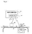
- Fig. 2 is a sectional side view of the printer.
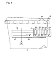
- Fig. 3 is a view for explaining the structure of the printer.
- the printer includes a ground-color-layer printing sub head 32a, in which a plurality of ink discharge ports for jetting ink droplets of, for example, white for printing a ground-color layer are aligned, and image printing sub heads 32b, 32c, 32d, and 32e, in which a plurality of ink discharge ports for jetting ink droplets of, for example, black, magenta, cyan, and yellow for printing an image are aligned.
- the sub head 32a, 32b, 32c, 32d, and 32e are aligned parallel to a line Y in an ink jet head 30 which is caused to perform a reciprocating movement, above a medium 10 placed on a platen 20, along the line Y parallel to a scanning direction.
- Portions of the image printing sub heads 32b, 32c, 32d, and 32e, in which the plurality of ink discharge ports for jetting the ink droplets for printing an image are aligned, are positioned at a front part in an X direction of the ink jet head 30 corresponding to the direction of sending forth and moving the medium 10 on the platen 20 by the sending unit 40.
- a portion of the ground-color-layer printing sub head 32a, in which the plurality of ink discharge ports for jetting the ink droplets for printing a ground-color layer are aligned is positioned at a rear part in the X direction of the ink jet head 30 corresponding to the direction of sending forth and moving the medium 10 on the platen 20 by the sending unit 40.
- the above-described portion of the ground-color-layer printing sub head 32a is positioned to be displaced in the X direction from the portions of the image printing sub heads 32b, 32c, 32d, and 32e, in which the plurality of ink discharge ports for jetting the ink droplets for printing an image are aligned, so as not to coincide in the line Y with the above-described portions of the image printing sub heads 32b, 32c, 32d, and 32e.
- the image printing sub heads 32b, 32c, 32d, and 32e which are aligned in the line Y in the ink jet head 30, and in which the plurality of ink discharge ports for jetting the ink droplets for printing an image are aligned, are positioned at the front part in the X direction of the ink jet head 30 corresponding to the direction of sending forth and moving the medium 10 on the platen 20 by the sending unit 40.
- the ground-color-layer printing sub head 32a which is aligned in the line Y in the ink jet head 30, and in which the plurality of ink discharge ports for jetting the ink droplets for printing a ground-color layer are aligned, is positioned at the rear part in the X direction of the ink jet head 30 corresponding to the direction of sending forth and moving the medium 10 on the platen 20 by the sending unit 40.
- the above-described portion of the ground-color-layer printing sub head 32a is positioned to be displaced by a predetermined distance or more in the X direction from the portions of the image printing sub heads 32b, 32c, 32d, and 32e, in which the plurality of ink discharge ports for jetting the ink droplets for printing an image are aligned, so as not to coincide in the line Y with the above-described portions of the image printing sub heads 32b, 32c, 32d, and 32e.
- Figs. 1 to 3 The printer illustrated in Figs. 1 to 3 is structured as described above. A printing method according to an embodiment of the present invention will now be described.
- the ink jet head 30 is caused to perform a reciprocating movement above the medium 10 in the line Y parallel to the scanning direction, and a ground-color layer 50 is printed into a belt shape along the line Y on the medium 10 placed on the platen 20, with the ink droplets of, for example, white jetted from the plurality of ink discharge ports which jet the ink droplets for printing a ground-color layer, and which are aligned on the ground-color-layer printing sub head 32a of the ink jet head 30.
- a grid roller 42 of the sending unit 40 is rotated by a predetermined angle in the X direction.
- the medium 10, a part of which has been nipped between the grid roller 42 and pinch rollers 44 is sent forth and moved on the platen 20 in the X direction corresponding to the direction of sending forth the medium 10.
- step (B) of the method the step (A) of keeping performing the continuous printing of the ground-color layer 50 on the medium 10 in the X direction continues to be performed, and the medium 10 is sent forth and moved on the platen 20 by the sending unit 40 more than a predetermined number of times in the X direction corresponding to the direction of sending forth the medium 10.
- an image 60 is printed along the line Y over the front surface of the ground-color layer 50, which has been previously and continuously printed on the medium 10 in the X direction, with the ink droplets jetted from the plurality of ink discharge ports which jet the ink droplets for printing an image, and which are aligned on the image printing sub heads 32b, 32c, 32d, and 32e of the ink jet head 30 that is caused to perform the reciprocating movement along the line Y.
- the medium 10 is sent forth and moved on the platen 20 by the sending unit 40 in the X direction corresponding to the direction of sending forth the medium 10.
- the following operation is removed in which the pinch rollers 44 of the sending unit 40 are rolled and returned on the ground-color layer 50 printed on the medium 10 to return in the direction opposite to the direction of sending forth the medium 10, while the pinch rollers 44 are pressed to contact the front surface of the ground-color layer 50.
- the ground-color layer 50 is prevented from having traces of the pinch rollers 44.
- the quality of the image 60 printed over the front surface of the ground-color layer 50 is prevented from being deteriorated.
- step (C) of the method the following operation included in the step (B) is halted in which the continuous printing of the ground-color layer 50 is kept performed on the medium 10 in the X direction with the ink droplets of, for example, white jetted from the plurality of ink discharge ports which jet the ink droplets for printing a ground-color layer, and which are aligned on the ground-color-layer printing sub head 32a of the ink jet head 30 that is caused to perform the reciprocating movement along the line Y.
- the ink droplets of, for example, white jetted from the plurality of ink discharge ports which jet the ink droplets for printing a ground-color layer, and which are aligned on the ground-color-layer printing sub head 32a of the ink jet head 30 that is caused to perform the reciprocating movement along the line Y.
- the following operation continues to be preformed in which the continuous printing of the image 60 is kept performed in the X direction over the front surface of the ground-color layer 50, which has been previously printed on the medium 10, with the ink droplets of, for example, black, magenta, cyan, and yellow jetted from the plurality of ink discharge ports which jet the ink droplets for printing an image, and which are aligned on the image printing sub heads 32b, 32c, 32d, and 32e of the ink jet head 30 that is caused to perform the reciprocating movement along the line Y.
- the above operation continues until an edge portion of the image 60 reaches either an edge portion of the ground-color layer 50, which has been previously and continuously printed on the medium 10 in the X direction, or a position inside the edge portion of the ground-color layer 50.
- the image 60 is continuously printed in the X direction over the front surface of the ground-color layer 50, which has been continuously printed on the medium 10 in the X direction, with the edge portion of the image 60 reaching either the edge portion of the ground-color layer 50 or the position inside the edge portion of the ground-color layer 50.
- the printing method using the printer as illustrated in Figs. 1 and 3 includes the above-described steps (A) to (C).
- Figs. 4 and 5 illustrate a printer according to another embodiment of the present invention.
- Fig. 4 is a view for explaining the structure of the printer.
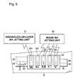
- Fig. 5 is a partially enlarged view of the printer for explaining the structure of the printer. The present printer will be described below.
- the present printer includes the sub head 32a which jets the ink droplets of, for example, white for printing a ground-color layer, and the sub heads 32b, 32c, 32d, and 32e which jet the ink droplets of, for example, black, magenta, cyan, and yellow for printing an image.
- the sub head 32a, 32b, 32c, 32d, and 32e are aligned in the line Y in the ink jet head 30 which is caused to perform the reciprocating movement, above the medium 10 placed on the a platen 20, along the line Y parallel to the scanning direction.
- the image printing sub heads 32b, 32c, 32d, and 32e and the ground-color-layer printing sub head 32a are aligned in the line Y, with no displacement in the X direction, so as to coincide with one another along the line Y.
- the plurality of ink discharge ports which jet the ink droplets for printing an image are aligned at front parts in an X direction of the sub heads (i.e., front half parts of the sub heads indicated by two-headed arrows in Fig. 5) corresponding to the direction of sending forth and moving the medium 10 on the platen 20 by the sending unit 40.
- the plurality of ink discharge ports which jet the ink droplets for printing a ground-color layer are aligned at a rear part in the X direction of the sub head (i.e., a rear half part of the sub head indicated by a two-headed arrow in Fig. 5) corresponding to the direction of sending forth and moving the medium 10 on the platen 20 by the sending unit 40.
- the present printer includes image ink jetting unit 80 which jets the ink droplets for printing an image from the plurality of ink discharge ports aligned at the front parts in the X direction of the image printing sub heads 32b, 32c, 32d, and 32e, and ground-color-layer ink jetting unit 70 which jets the ink droplets for printing a ground-color layer from the plurality of ink discharge ports aligned at the rear part in the X direction of the ground-color-layer printing sub head 32a.
- the image ink jetting unit 80 and the ground-color-layer ink jetting unit 70 are formed by, for example, an electric control circuit of a host computer 100 which drives the printer.
- the printer illustrated in Figs. 4 and 5 is structured as described above. A printing method according to an embodiment of the present invention will now be described.
- the ink jet head 30 is caused to perform the reciprocating movement along the line Y parallel to the scanning direction, and a ground-color layer 50 is printed into a belt shape on the medium 10 along the line Y with the ink droplets of, for example, white jetted by the ground-color-layer ink jetting unit 70 from the plurality of ink discharge ports aligned at the rear part in the X direction of the ground-color-layer printing sub head 32a of the ink jet head 30.
- the medium 10 is sent forth and moved on the platen 20 by the sending unit 40 in the X direction corresponding to the direction of sending forth the medium 10.
- the above-described operations are repeated to keep performing the continuous printing of the ground-color layer 50 on the medium 10 in the X direction.
- the step (A) of keeping performing the continuous printing of the ground-color layer 50 on the medium 10 in the X direction continues to be performed, and the medium 10 is sent forth and moved on the platen 20 by the sending unit 40 more than a predetermined number of times in the X direction corresponding to the direction of sending forth the medium 10.
- the front parts in the X direction of the image printing sub heads 32b, 32c, 32d, and 32e of the ink jet head 30, in which the plurality of ink discharge ports for jetting the ink droplets for printing an image are aligned reach respective positions above the ground-color layer 50, which has been previously and continuously printed on the medium 10 in the X direction.
- an image 60 is printed along the line Y over the front surface of the ground-color layer 50, which has been previously printed on the medium 10, with the ink droplets of, for example, black, magenta, cyan, and yellow jetted by the image ink jetting unit 80 from the plurality of ink discharge ports aligned at the front parts in the X direction of the image printing sub heads 32b, 32c, 32d, and 32e of the ink jet head 30 that is caused to perform the reciprocating movement along the line Y.
- the medium 10 is sent forth and moved on the platen 20 by the sending unit 40 in the X direction corresponding to the direction of sending forth the medium 10.
- the above-described operations are repeated to keep performing the continuous printing of the ground-color layer 50 on the medium 10 in the X direction, and to keep performing the continuous printing of the image 60 in the X direction over the front surface of the ground-color layer 50, which has been previously and continuously printed 50 on the medium 10 in the X direction.
- the image 60 is printed over the front surface of the ground-color layer 50, which has been previously printed on the medium 10, there is no need to move and return the medium 10, on which the ground-color layer 50 has been printed, in the direction opposite to the direction of sending forth the medium 10. Further, the following operation is removed in which the pinch rollers 44 of the sending unit 40 are rolled and moved on the ground-color layer 50 printed on the medium 10 to return in the direction opposite to the direction of sending forth the medium 10, while the pinch rollers 44 are pressed to contact the front surface of the ground-color layer 50.
- the ground-color layer 50 is prevented from having the traces of the pinch rollers 44. Thereby, the quality of the image 60 printed over the front surface of the ground-color layer 50 is prevented from being deteriorated.
- step (C) of the method the following operation included in the step (B) is halted in which the continuous printing of the ground-color layer 50 is kept performed on the medium 10 in the X direction with the ink droplets of, for example, white jetted by the ground-color-layer ink jetting unit 70 from the plurality of ink discharge ports aligned at the rear part in the X direction of the ground-color-layer printing sub head 32a of the ink jet head 30 that is caused to perform the reciprocating movement along the line Y.
- the following operation continues to be preformed in which the continuous printing of the image 60 is kept performed in the X direction over the front surface of the ground-color layer 50, which has been previously and continuously printed on the medium 10 in the X direction, with the ink droplets of, for example, black, magenta, cyan, and yellow jetted by the image ink jetting unit 80 from the plurality of ink discharge ports aligned at the front parts in the X direction of the image printing sub heads 32b, 32c, 32d, and 32e of the ink jet head 30 that is caused to perform the reciprocating movement along the line Y.
- the above operation continues until an edge portion of the image 60 reaches either an edge portion of the ground-color layer 50, which has been continuously printed on the medium 10 in the X direction, or a position inside the edge portion of the ground-color layer 50.
- the image 60 is continuously printed in the X direction over the front surface of the ground-color layer 50, which has been continuously printed on the medium 10 in the X direction, with the edge portion of the image 60 reaching either the edge portion of the ground-color layer 50 or the position inside the edge portion of the ground-color layer 50.
- the printing method using the printer as illustrated in Figs. 4 and 5 includes the above-described steps (A) to (C).
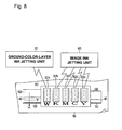
- Fig. 6 illustrates a printer according to an embodiment of the present invention.
- Fig. 6 is a view for explaining the structure of the printer. The present printer will be described below.
- the portion of the ground-color-layer printing sub head 32a which is aligned along the line Y in the ink jet head 30 of the printer, and in which the plurality of ink discharge ports for jetting the ink droplets of, for example, white for printing a ground-color layer are aligned, is positioned at a front part in the X direction of the ink jet head 30 corresponding to the direction of sending forth and moving the medium 10 on the platen 20 by the sending unit 40.
- the portions of the image printing sub heads 32b, 32c, 32d, and 32e, which are aligned along the line Y in the ink jet head 30 of the printer, and in which the plurality of ink discharge ports for jetting the ink droplets of, for example, black, magenta, cyan, and yellow for printing an image are aligned, are positioned at a rear part in the X direction of the ink jet head 30 corresponding to the direction of sending forth and moving the medium 10 on the platen 20 by the sending unit 40.
- the above-described portions of the image printing sub heads 32b, 32c, 32d, and 32e are positioned to be displaced in the X direction from the portion of the ground-color-layer printing sub head 32a, in which the plurality of ink discharge ports for jetting the ink droplets for printing a ground-color layer are aligned, so as not to coincide along the line Y with the above-described portions of the ground-color-layer printing sub head 32a.
- the ground-color-layer printing sub head 32a which is aligned along the line Y in the ink jet head 30, and in which the plurality of ink discharge ports for jetting the ink droplets for printing a ground-color layer are aligned, is positioned at the front part in the X direction of the ink jet head 30 corresponding to the direction of sending forth and moving the medium 10 on the platen 20 by the sending unit 40.
- the image printing sub heads 32b, 32c, 32d, and 32e which are aligned along the line Y in the ink jet head 30, and in which the plurality of ink discharge ports for jetting the ink droplets for printing an image are aligned, are positioned at the rear part in the X direction of the ink jet head 30 corresponding to the direction of sending forth and moving the medium 10 on the platen 20 by the sending unit 40.
- the image printing sub heads 32b, 32c, 32d, and 32e are positioned to be displaced by a predetermined distance or more in the X direction from the portion of the ground-color-layer printing sub head 32a, in which the plurality of ink discharge ports for jetting the ink droplets for printing a ground-color layer are aligned, so as not to coincide along the line Y with the above-described portion of the ground-color-layer printing sub head 32a.
- the present printer is similar in structure to the printer illustrated in Figs. 1 to 3 except for the point described above. A printing method according to an embodiment of the present invention will now be described.
- the ink jet head 30 is caused to perform the reciprocating movement above the medium 10 along the line Y parallel to the scanning direction, and an image 60 is printed along the line Y on the medium 10 placed on the platen 20 with the ink droplets of, for example, black, magenta, cyan, and yellow jetted from the plurality of ink discharge ports which jet the ink droplets for printing an image, and which are aligned on the image printing sub heads 32b, 32c, 32d, and 32e of the ink jet head 30 of the printer.
- the grid roller 42 of the sending unit 40 is rotated by a predetermined angle in the X direction.
- the medium 10, a part of which has been nipped between the grid roller 42 and the pinch rollers 44 is send forth and moved on the platen 20 in the X direction corresponding to the direction of sending the medium 10.
- step (B) of the method the step (A) of keeping performing the continuous printing of the image 60 on the medium 10 in the X direction continues to be performed, and the medium 10 is sent forth and moved on the platen 20 by the sending unit 40 more than a predetermined number of times in the X direction corresponding to the direction of sending forth the medium 10.
- the portion of the ground-color-layer printing sub head 32a in which the plurality of ink discharge ports for jetting the ink droplets for printing a ground-color layer are aligned, and which is positioned to at the front part in the X direction of the ink jet head 30 corresponding to the direction of sending forth the medium 10, to be displaced from the image printing sub heads 32b, 32c, 32d, and 32e, reaches a position above the image 60, which has been previously and continuously printed on the medium 10 in the X direction.
- a ground-color layer 50 is printed along the line Y over the back surface of the image 60, which has been previously and continuously printed on the medium 10 in the X direction, with the ink droplets of, for example, white jetted from the plurality of ink discharge ports which jet the ink droplets for printing a ground-color layer, and which are aligned on the ground-color-layer printing sub head 32a of the ink jet head 30 that is caused to perform the reciprocating movement along the line Y.
- the medium 10 is sent forth and moved on the platen 20 by the sending unit 40 in the X direction corresponding to the direction of sending forth the medium 10.
- the ground-color layer 50 is printed over the back surface of the image 60, which has been previously printed on the medium 10, there is no need to move and return the medium 10, on which the image 60 has been printed, on the platen 20 in the direction opposite to the direction of sending forth the medium 10.
- the following operation is removed in which the pinch rollers 44 of the sending unit 40 are rolled and moved on the image 60 printed on the medium 10 to return in the direction opposite to the direction of sending forth the medium 10, while the pinch rollers 44 are pressed to contact the back surface of image 60.
- the image 60 is prevented from having the traces of the pinch rollers 44.
- the quality of the image 60 is prevented from being deteriorated.
- step (C) of the method the following operation included in the step (B) is halted in which the continuous printing of the image 60 is kept performed on the medium 10 in the X direction with the ink droplets of, for example, black, magenta, cyan, and yellow jetted from the plurality of ink discharge ports which jet the ink droplets for printing an image, and which are included in the image printing sub heads 32b, 32c, 32d, and 32e of the ink jet head 30 that is caused to perform the reciprocating movement along the line Y.
- the ink droplets of, for example, black, magenta, cyan, and yellow jetted from the plurality of ink discharge ports which jet the ink droplets for printing an image, and which are included in the image printing sub heads 32b, 32c, 32d, and 32e of the ink jet head 30 that is caused to perform the reciprocating movement along the line Y.
- the following operation continues to be preformed in which the continuous printing of the ground-color layer 50 is kept performed in the X direction over the back surface of the image 60, which has been previously printed on the medium 10, with the ink droplets of, for example, white jetted from the plurality of ink discharge ports which jet the ink droplets for printing a ground-color layer, and which are included in the ground-color-layer printing sub head 32a of the ink jet head 30 that is caused to perform the reciprocating movement along the line Y.
- the above operation continues until an edge portion of the ground-color layer 50 reaches either an edge portion of the image 60, which has been previously and continuously printed on the medium 10 in the X direction, or a position outside the edge portion of the image 60.
- the ground-color layer 50 is continuously printed in the X direction over the back surface of the image 60, which has been continuously printed on the medium 10 in the X direction, with the edge portion of the ground-color layer 50 reaching either the edge portion of the image 60 or the position outside the edge portion of the image 60.
- the printing method using the printer as illustrated in Fig. 6 includes the above-described steps (A) to (C).
- Fig. 7 illustrates another printer according to an embodiment of the present invention.
- Fig. 7 is a partially enlarged view of the printer for explaining the structure of the printer. The present printer will be described below.
- the image printing sub heads 32b, 32c, 32d, and 32e and the ground-color-layer printing sub head 32a are aligned in the line Y in the ink jet head 30 so as to coincide with one another along the line Y.
- the plurality of ink discharge ports which jet the ink droplets of, for example, black, magenta, cyan, and yellow for printing an image are aligned at rear parts in the X direction of the sub heads (i.e., rear parts of the sub heads indicated by two-headed arrows in Fig. 7) corresponding to the direction of sending forth and moving the medium 10 on the platen 20 by the sending unit 40.
- the plurality of ink discharge ports which jet the ink droplets of, for example, white for printing a ground-color layer are aligned at a front part in the X direction of the sub head (i.e., a front part of the sub head indicated by a two-headed arrow in Fig. 7) corresponding to the direction of sending forth and moving the medium 10 on the platen 20 by the sending unit 40.
- the present printer includes the image ink jetting unit 80 which jets the ink droplets for printing an image from the plurality of ink discharge ports aligned at the rear parts in the X direction of the image printing sub heads 32b, 32c, 32d, and 32e, and the ground-color-layer ink jetting unit 70 which jets the ink droplets for printing a ground-color layer from the plurality of ink discharge ports aligned at the front part in the X direction of the ground-color-layer printing sub head 32a.
- the ground-color-layer ink jetting unit 70 and the image ink jetting unit 80 are formed by, for example, the electric control circuit of the host computer 100 which drives the printer.
- the present printer is similar in structure to the printer illustrated in Figs. 4 and 5 except for the point described above. A printing method according to an embodiment of the present invention will now be described.
- the ink jet head 30 is caused to perform the reciprocating movement along the line Y parallel to the scanning direction, and an image 60 is printed on the medium 10 in the X direction with the ink droplets of, for example, black, magenta, cyan, and yellow jetted by the image ink jetting unit 80 from the plurality of ink discharge ports aligned at the rear parts in the X direction of the image printing sub heads 32b, 32c, 32d, and 32e of the ink jet head 30. Thereafter, the medium 10 is sent forth and moved on the platen 20 by the sending unit 40 in the X direction corresponding to the direction of sending forth the medium 10. The above-described operations are repeated to keep performing the continuous printing of the image 60 on the medium 10 in the X direction.
- a step (B) of the method the step (A) of keeping performing the continuous printing of the image 60 on the medium 10 in the X direction continues to be performed, and the medium 10 is sent forth and moved on the platen 20 by the sending unit 40 more than a predetermined number of times in the X direction corresponding to the direction of sending forth the medium 10. Then, the front part in the X direction of the ground-color-layer printing sub head 32a of the ink jet head 30, in which the plurality of ink discharge ports for jetting the ink droplets for printing a ground-color layer are aligned, reaches a position above the image 60, which has been printed on the medium 10.
- a ground-color layer 50 is printed along the line Y over the back surface of the image 60, which has been previously printed on the medium 10, with the ink droplets of, for example, white jetted by the ground-color-layer ink jetting unit 70 from the plurality of ink discharge ports which jet the ink droplets for printing a ground-color layer, and which are aligned at the front part in the X direction of the ground-color-layer printing sub head 32a of the ink jet head 30 that is caused to perform the reciprocating movement along the line Y.
- the medium 10 is sent forth and moved on the platen 20 by the sending unit 40 in the X direction corresponding to the direction of sending forth the medium 10.
- the above-described operations are repeated to keep performing the continuous printing of the image 60 on the medium 10 in the X direction, and to keep performing the continuous printing of the ground-color layer 50 in the X direction over the back surface of the image 60, which has been previously and continuously printed on the medium 10 in the X direction.
- the ground-color layer 50 is printed over the back surface of the image 60, which has been previously printed on the medium 10, there is no need to move and return the medium 10, on which the image 60 has been printed, in the direction opposite to the direction of sending forth the medium 10.
- the following operation is removed in which the pinch rollers 44 of the sending unit 40 are rolled and moved on the image 60 printed on the medium 10 to return in the direction opposite to the direction of sending forth the medium 10, while the pinch rollers 44 are pressed to contact the back surface of the image 60.
- the image 60 is prevented from having the traces of the pinch rollers 44.
- the quality of the image 60 is prevented from being deteriorated.
- step (C) of the method the following operation included in the step (B) is halted in which the continuous printing of the image 60 is kept performed on the medium 10 in the X direction with the ink droplets jetted by the image ink jetting unit 80 from the plurality of ink discharge ports which jet the ink droplets for printing an image, and which are aligned at the rear parts in the X direction of the image printing sub heads 32b, 32c, 32d, and 32e of the ink jet head 30 that is caused to perform the reciprocating movement along the line Y.
- the following operation continues to be preformed in which the continuous printing of the ground-color layer 50 in the X direction over the back surface of the image 60, which has been previously and continuously printed on the medium 10 in the X direction, with the ink droplets jetted by the ground-color-layer ink jetting unit 70 from the plurality of ink discharge ports which jet the ink droplets for printing a ground-color layer, and which are aligned at the front part in the X direction of the ground-color-layer printing sub head 32a of the ink jet head 30 that is caused to perform the reciprocating movement along the line Y.
- the above operation continues until an edge portion of the ground-color layer 50 reaches either an edge portion of the image 60, which has been continuously printed on the medium 10 in the X direction, or a position outside the edge portion of the image 60.
- the ground-color layer 50 is continuously printed in the X direction over the back surface of the image 60, which has been continuously printed on the medium 10 in the X direction, with the edge portion of the ground-color layer 50 reaching either the edge portion of the image 60 or the position outside the edge portion of the image 60.
- the printing method using the printer as illustrated in Fig. 7 includes the above-described steps (A) to (C).
- the grid roller 42 of the sending unit 40 may be configured to be rotatable both in the forward direction and the backward direction so that the medium 10 can be sent forth and moved on the platen 20 by the sending unit 40 in the X direction in either the forward direction or the backward direction according to the selected direction.
- the direction of sending forth and moving the medium 10 by using the sending unit 40 may be selected to be opposite to the direction used in the printing method as described above so that the image 60 is printed on the medium 10 and thereafter the ground-color layer 50 is printed over the back surface of the image 60.
- the printer illustrated in Fig. 3 may be configured to have a similar effect to the effect of the printer, being capable of printing the ground-color layer 50 over the back surface of the image 60 with no need to reverse, in the X direction, the position of the ground-color-layer printing sub head 32a, which is positioned at the rear part in the X direction of the ink jet head 30, and the position of the image printing sub heads 32b, 32c, 32d, and 32e, which are positioned at the front part in the X direction of the ink jet head 30.
- a printing method having a similar effect to the effect of the printing method may be provided.
- the printer illustrated in Fig. 5 may be configured to have a similar effect to the effect of the printer, being capable of printing the ground-color layer 50 over the back surface of the image 60 with no need to reverse, in the X direction, the position of the plurality of ink discharge ports which jet the ink droplets for printing a ground-color layer, and which are aligned at the rear part in the X direction of the ground-color-layer printing sub head 32a, and the position of the plurality of ink discharge ports which jet the ink droplets for printing an image, and which are aligned at the front parts in the X direction of the image printing sub heads 32b, 32c, 32d, and 32e.
- a printing method having a similar effect to the effect of the printing method may be provided.
- the sending unit 40 may be configured to be capable of sending forth and moving the medium 10 on the platen 20 in the X direction in either the forward direction or the backward direction according to the selected direction.
- the direction of sending forth and moving the medium 10 by using the sending unit 40 may be selected to be opposite to the direction used in the printing method as described above so that the ground-color layer 50 is printed on the medium 10 and thereafter the image 60 is printed over the front surface of the ground-color layer 50.
- the printer illustrated in Fig. 6 may be configured to have a similar effect to the effect of the printer, being capable of printing the image 60 over the front surface of the ground-color layer 50 with no need to reverse, in the X direction, the position of the image printing sub heads 32b, 32c, 32d, and 32e, which are positioned at the rear part in the X direction of the ink jet head 30, and the position of the ground-color-layer printing sub head 32a, which is positioned at the front part in the X direction of the ink jet head 30.
- a printing method having a similar effect to the effect of the printing method may be provided.
- the printer illustrated in Fig. 7 may be configured to have a similar effect to the effect of the printer, being capable of printing the image 60 over the front surface of the ground-color layer 50 with no need to reverse, in the X direction, the position of the plurality of ink discharge ports which jet the ink droplets for printing a ground-color layer, and which are aligned at the front part in the X direction of the ground-color-layer printing sub head 32a, and the position of the plurality of ink discharge ports which jet the ink droplets for printing an image, and which are aligned at the rear parts in the X direction of the image printing sub heads 32b, 32c, 32d, and 32e.
- a printing method having a similar effect to the effect of the printing method may be provided.
- the printer may preferably include drying unit 90 for drying the ground-color layer 50 printed on the medium 10 with the ink droplets jetted from the plurality of ink discharge ports which jet the ink droplets for printing a ground-color layer, and which are aligned on the ground-color-layer printing sub head 32a.
- the printer may preferably include the drying unit 90 for drying the image 60 printed on the medium 10 with the ink droplets jetted from the plurality of ink discharge ports which jet the ink droplets for printing an image, and which are aligned on the image printing sub heads 32b, 32c, 32d, and 32e.
- the ground-color layer 50 or the image 60 previously printed on the medium 10 is forcefully dried by the drying unit 90.
- the drying unit 90 may preferably function as a movement/standby time setting mechanism which sets the movement/standby time of the medium 10, during which the medium 10 is sent forth and moved on the platen 20 by the sending unit 40 in the X direction corresponding to the direction of sending forth the medium 10, to be a long or short time period.
- the drying unit 90 including the movement/standby time setting mechanism may be preferably formed by, for example, the electric control circuit of the host computer 100 which drives the printer.
- the drying unit 90 may also function as a head idling mechanism which repeats an operation of causing the ink jet head 30 to perform the reciprocating movement in an idling manner along the line Y corresponding to the scanning direction, with no ink droplets jetted from the sub heads 32a, 32b, 32c, 32d, and 32d aligned on the ink jet head 30.
- the operation may be repeated during a time period in which the ground-color layer 50 is printed on the medium 10 and thereafter the image 60 is printed over the front surface of the ground-color layer 50, or during a time period in which the image 60 is printed on the medium 10 and thereafter the ground-color layer 50 is printed over the back surface of the image 60.
- the drying unit 90 including the head idling mechanism may be preferably formed by, for example, the electric control circuit of the host computer 100 which drives the printer.
- the drying unit 90 may also function as a distance setting mechanism which adjusts a displacement in the X direction between the image printing sub heads 32b, 32c, 32d, and 32e of the ink jet head 30, in which the plurality of ink discharge ports for jetting the ink droplets for printing an image are aligned, and the ground-color-layer printing sub head 32a of the ink jet head 30, in which the plurality of ink discharge ports for jetting the ink droplets for printing a ground-color layer are aligned, to be a long or short value.
- the drying unit 90 may function as a distance setting mechanism which adjusts a displacement in the X direction between the front or rear parts in the X direction of the image printing sub heads 32b, 32c, 32d, and 32e of the ink jet head 30, in which the plurality of ink discharge ports for jetting the ink droplets for printing an image are aligned, and the rear or front part in the X direction of the ground-color-layer printing sub head 32a of the ink jet head 30, in which the plurality of ink discharge ports for jetting the ink droplets for printing a ground-color layer are aligned, to be a long or short value, such as a distance substantially corresponding to the first third of the length in the X direction of the respective portions of the sub heads 32a, 32b, 32c, 32d, and 32e, in which the plurality of ink discharge ports are aligned, as indicated by two-headed arrows in Fig. 8.
- the drying unit 90 may be configured to sufficiently dry the image 60 or the ground-color layer 50, which has been previously printed on the medium 10, during a standby time.
- the standby time may be set to be a long or short time period included in a time period during which the ground-color layer 50 is printed on the medium 10 and thereafter the image 60 is printed over the front surface of the ground-color layer 50, or in a time period during which the image 60 is printed on the medium 10 and thereafter the ground-color layer 50 is printed over the back surface of the image 60.
- the drying unit 90 may also function as heating and drying unit for heating and drying the ground-color layer 50 or the image 60, which has been previously printed on the medium 10, by using a heater such as an electric heater, or as hot-air heating unit for applying hot air to the ground-color layer 50 or the image 60, which has been previously printed on the medium 10, to dry the ground-color layer 50 or the image 60.
- a heater such as an electric heater
- hot-air heating unit for applying hot air to the ground-color layer 50 or the image 60, which has been previously printed on the medium 10, to dry the ground-color layer 50 or the image 60.
- the drying unit 90 may be configured to sufficiently dry the ground-color layer 50 or the image 60, which has been previously printed on the medium 10, by using the heating and drying unit or the hot-air drying unit.
- the image 60 may be preferably printed over the front surface of the ground-color layer 50, which has been previously printed on the medium 10 and then sufficiently dried, or the ground-color layer 50 may be preferably printed over the back surface of the image 60, which has been previously printed on the medium 10 and then sufficiently dried.
- the quality of the image 60 can be preferably prevented from being deteriorated due to mixture of undried ink of the image 60 and the ground-color layer 50 which are printed over each other.
- the ground-color-layer printing sub head 32a may be changed into a sub head which jets ink droplets for printing an image-fixing undercoat layer from the ink discharge ports which jet the ink droplets for the ground-color layer.
- an undercoat layer (not illustrated) for fixing the image 60 may be printed on the medium 10 by using the printer and a printing method similar to the printing method, so that the image 60 is stably and securely fixed and printed over the front surface of the undercoat layer, and that the quality of the image 60 printed over the front surface of the undercoat layer is improved.
- the ground-color-layer printing sub head 32a may be changed into a sub head which jets ink droplets for printing an overcoat layer for protecting the image 60 from the ink discharge ports which jet the ink droplets for the ground-color layer.
- the image 60 may be printed on the medium 10 and thereafter the front surface of the image 60, which has been printed on the medium 10, may be protected by an overcoat layer (not illustrated) so that the weather resistance of the image 60 is improved.
- the printer according to the embodiments of the present invention and the printing method according to the embodiments of the present invention can be widely used to print an image on a transparent medium, such as a film and glass, or on a medium which is difficult to be directly printed with an image, such as a resin sheet, fabric, and leather.
Landscapes
- Ink Jet (AREA)
Applications Claiming Priority (1)
| Application Number | Priority Date | Filing Date | Title |
|---|---|---|---|
| JP2005235615A JP5425357B2 (ja) | 2005-08-16 | 2005-08-16 | インクジェットプリンタとそれを用いたプリント方法 |
Publications (2)
| Publication Number | Publication Date |
|---|---|
| EP1754610A1 true EP1754610A1 (fr) | 2007-02-21 |
| EP1754610B1 EP1754610B1 (fr) | 2011-05-18 |
Family
ID=37110204
Family Applications (1)
| Application Number | Title | Priority Date | Filing Date |
|---|---|---|---|
| EP06291309A Revoked EP1754610B1 (fr) | 2005-08-16 | 2006-08-16 | Tête à jet d'encre, imprimante l'utilisant et pocédé d'impression |
Country Status (5)
| Country | Link |
|---|---|
| US (2) | US7798602B2 (fr) |
| EP (1) | EP1754610B1 (fr) |
| JP (1) | JP5425357B2 (fr) |
| CN (1) | CN100503256C (fr) |
| AT (1) | ATE509770T1 (fr) |
Cited By (2)
| Publication number | Priority date | Publication date | Assignee | Title |
|---|---|---|---|---|
| EP2000314A1 (fr) * | 2007-06-04 | 2008-12-10 | Dainippon Screen Mfg., Co., Ltd. | Appareil d'enregistrement à jet d'encre |
| CN105936186A (zh) * | 2016-06-16 | 2016-09-14 | 深圳市全印图文技术有限公司 | 一种可实现组合喷印的印花装置 |
Families Citing this family (55)
| Publication number | Priority date | Publication date | Assignee | Title |
|---|---|---|---|---|
| JP5123519B2 (ja) * | 2006-11-24 | 2013-01-23 | 株式会社ミマキエンジニアリング | 印刷装置及び印刷方法 |
| US8167423B2 (en) * | 2007-12-28 | 2012-05-01 | Seiko Epson Corporation | Ink jet apparatus |
| JP5128312B2 (ja) | 2008-02-29 | 2013-01-23 | 株式会社ミマキエンジニアリング | 紫外線硬化型インクジェットプリンタ、紫外線硬化型インクジェットプリンタの印刷方法及びヘッドユニット構造 |
| JP5347300B2 (ja) | 2008-03-28 | 2013-11-20 | セイコーエプソン株式会社 | 印刷装置 |
| JP5195040B2 (ja) * | 2008-05-30 | 2013-05-08 | セイコーエプソン株式会社 | 印刷装置 |
| JP5211891B2 (ja) * | 2008-06-26 | 2013-06-12 | セイコーエプソン株式会社 | 記録方法、記録装置及び動作制御プログラム |
| JP2010076102A (ja) * | 2008-09-24 | 2010-04-08 | Mutoh Industries Ltd | 印字装置及び印字方法 |
| JP5560681B2 (ja) * | 2008-12-08 | 2014-07-30 | セイコーエプソン株式会社 | 記録方法、記録物、記録装置及び動作制御プログラム |
| JP5825383B2 (ja) * | 2008-12-09 | 2015-12-02 | セイコーエプソン株式会社 | 画像記録方法、画像記録システム |
| JP5515650B2 (ja) * | 2008-12-09 | 2014-06-11 | セイコーエプソン株式会社 | 画像記録方法、画像記録システム |
| JP5604790B2 (ja) * | 2009-02-04 | 2014-10-15 | セイコーエプソン株式会社 | 印刷方法及び印刷装置 |
| JP5304517B2 (ja) | 2009-07-28 | 2013-10-02 | セイコーエプソン株式会社 | 流体噴射装置、及び、流体噴射方法 |
| JP5304516B2 (ja) * | 2009-07-28 | 2013-10-02 | セイコーエプソン株式会社 | 流体噴射装置、及び、流体噴射方法 |
| JP5338547B2 (ja) * | 2009-07-31 | 2013-11-13 | セイコーエプソン株式会社 | 流体噴射装置、及び、流体噴射方法 |
| JP5326924B2 (ja) * | 2009-08-18 | 2013-10-30 | セイコーエプソン株式会社 | 流体噴射装置、及び、流体噴射方法 |
| JP5593795B2 (ja) * | 2009-12-15 | 2014-09-24 | セイコーエプソン株式会社 | 流体噴射装置、及び、流体噴射方法 |
| JP5440333B2 (ja) * | 2009-12-15 | 2014-03-12 | セイコーエプソン株式会社 | 流体噴射装置、及び、流体噴射方法 |
| JP5625397B2 (ja) * | 2010-03-09 | 2014-11-19 | セイコーエプソン株式会社 | 印刷装置 |
| JP5764868B2 (ja) | 2010-03-10 | 2015-08-19 | セイコーエプソン株式会社 | 印刷装置及び印刷方法 |
| JP2011241500A (ja) * | 2010-05-18 | 2011-12-01 | Toshinkogyo Co Ltd | インクジェット捺染方法及びインクジェット捺染装置 |
| JP5516249B2 (ja) | 2010-09-02 | 2014-06-11 | セイコーエプソン株式会社 | 印刷装置、印刷方法 |
| JP5707828B2 (ja) | 2010-09-30 | 2015-04-30 | セイコーエプソン株式会社 | 液体噴射装置の制御方法 |
| US8613490B2 (en) * | 2010-12-14 | 2013-12-24 | Seiko Epson Corporation | Fluid ejecting apparatus and fluid ejecting method |
| JP5793870B2 (ja) * | 2011-01-24 | 2015-10-14 | セイコーエプソン株式会社 | 印刷装置及び印刷方法 |
| JP5738613B2 (ja) * | 2011-01-31 | 2015-06-24 | 株式会社Screenホールディングス | インクジェットプリンタおよび画像形成方法 |
| JP5772076B2 (ja) | 2011-03-08 | 2015-09-02 | セイコーエプソン株式会社 | 印刷方法、及び印刷装置 |
| JP2012187889A (ja) * | 2011-03-14 | 2012-10-04 | Seiko Epson Corp | 遮光層形成処理装置および遮光層形成処理方法 |
| JP2012192601A (ja) * | 2011-03-16 | 2012-10-11 | Seiko Epson Corp | 画像形成処理装置および画像形成処理方法 |
| JP5779953B2 (ja) | 2011-04-14 | 2015-09-16 | セイコーエプソン株式会社 | 印刷装置、印刷方法、及び、プログラム |
| JP2012223931A (ja) | 2011-04-18 | 2012-11-15 | Seiko Epson Corp | 画像処理装置、印刷装置、画像処理方法および画像処理プログラム |
| JP5803251B2 (ja) | 2011-05-09 | 2015-11-04 | セイコーエプソン株式会社 | 画像形成装置、及び、画像形成方法 |
| JP5776319B2 (ja) | 2011-05-12 | 2015-09-09 | セイコーエプソン株式会社 | 画像形成装置、及び、画像形成方法 |
| JP5927775B2 (ja) * | 2011-05-12 | 2016-06-01 | セイコーエプソン株式会社 | 画像形成装置、及び、画像形成方法 |
| JP5899665B2 (ja) * | 2011-06-07 | 2016-04-06 | セイコーエプソン株式会社 | 印刷装置、印刷方法、及び、プログラム |
| CN103370200B (zh) * | 2011-08-01 | 2015-07-22 | 北京美科艺数码科技发展有限公司 | 喷墨打印装置及其打印方法 |
| JP5866849B2 (ja) * | 2011-08-03 | 2016-02-24 | セイコーエプソン株式会社 | 液体吐出装置、及び、画像形成方法 |
| CN103042834B (zh) * | 2011-10-14 | 2015-01-07 | 武汉海蓝生物技术有限公司 | 一种低粘度水性uv颜料墨水及其打印方法 |
| JP5903987B2 (ja) * | 2012-03-29 | 2016-04-13 | セイコーエプソン株式会社 | 印刷装置、及び、印刷方法 |
| CN103921549B (zh) * | 2013-01-14 | 2016-01-27 | 佛山市南海区希望陶瓷机械设备有限公司 | 连续扫描喷墨打印机 |
| JP2014168851A (ja) * | 2013-03-01 | 2014-09-18 | Mimaki Engineering Co Ltd | 印刷装置及び印刷方法 |
| CN105764699B (zh) * | 2013-09-27 | 2017-06-23 | 北京美科艺数码科技发展有限公司 | 喷墨打印方法和喷墨打印装置 |
| JP2014051100A (ja) * | 2013-12-02 | 2014-03-20 | Seiko Epson Corp | 液体噴射装置 |
| JP5928633B2 (ja) * | 2015-04-15 | 2016-06-01 | ブラザー工業株式会社 | インクジェットヘッド |
| EP3296110B1 (fr) * | 2015-05-11 | 2020-07-15 | Konica Minolta, Inc. | Appareil d'enregistrement à jet d'encre |
| US9809024B2 (en) | 2015-06-11 | 2017-11-07 | Ricoh Company, Ltd. | Image forming apparatus |
| US10144213B2 (en) | 2016-06-08 | 2018-12-04 | Ricoh Company, Ltd. | Printing apparatus, recording medium storing program, and printing method |
| CN106042658B (zh) * | 2016-07-29 | 2017-09-22 | 杭州印象数码科技有限公司 | 印花打印设备 |
| JP6186489B1 (ja) * | 2016-12-20 | 2017-08-23 | ローランドディー.ジー.株式会社 | インクジェットプリンタ |
| JP2018144410A (ja) * | 2017-03-08 | 2018-09-20 | ローランドディー.ジー.株式会社 | インクジェットプリンタ |
| CN110027325B (zh) * | 2019-04-29 | 2020-03-13 | 深圳市汉森软件有限公司 | 打印控制方法、装置、设备及打印机 |
| IT201900017090A1 (it) * | 2019-09-24 | 2021-03-24 | Keraglass Ind S R L | Metodo di controllo di una macchina di stampa a getto di inchiostro su lastre |
| CN111086338B (zh) * | 2019-12-16 | 2021-08-27 | 广州晶绘实业有限公司 | 一种小批量高速打印的打印方法及打印机 |
| CN113085401B (zh) * | 2021-04-06 | 2023-03-24 | 北京华科恒润智能科技有限公司 | 墙体彩绘打印方法及装置、电子设备和存储介质 |
| CN113103767B (zh) * | 2021-04-14 | 2022-08-16 | 苏州市锦展数码科技有限公司 | 一种采用多种喷印材料进行混合印刷及热转印的方法 |
| JP2025042536A (ja) * | 2023-09-14 | 2025-03-27 | 株式会社ミマキエンジニアリング | 印刷システムおよび印刷装置の制御方法 |
Citations (7)
| Publication number | Priority date | Publication date | Assignee | Title |
|---|---|---|---|---|
| JP2002038063A (ja) * | 2000-07-31 | 2002-02-06 | Seiko Epson Corp | 白色インクを含むインクセット及びこれを用いたインクジェット記録方法 |
| JP2002205381A (ja) | 2001-01-11 | 2002-07-23 | Mimaki Engineering Co Ltd | インクジェットプリンタとそれを用いた複数色の絵図又は文字のプリント方法 |
| EP1331100A2 (fr) * | 2002-01-25 | 2003-07-30 | Konica Corporation | Imprimante à jet d'encre |
| US20050083363A1 (en) * | 2003-10-16 | 2005-04-21 | Canon Kabushiki Kaisha | Method and apparatus for ink jet printing |
| EP1527892A1 (fr) * | 2003-10-29 | 2005-05-04 | Konica Minolta Medical & Graphic, Inc. | Appareil d'enregistrement à jet d'encre |
| EP1547793A1 (fr) * | 2002-05-22 | 2005-06-29 | Ricoh Company, Ltd. | Liquide de traitement pour impression a jet d'encre, jeu d'encres, cartouche dans laquelle ces liquides sont charges, appareil et procede de formation d'une image par impression a jet d'encre |
| JP2005235615A (ja) | 2004-02-20 | 2005-09-02 | Hitachi Maxell Ltd | アダプタパネル、電子機器、及びケーブルコネクタ認識システム |
Family Cites Families (31)
| Publication number | Priority date | Publication date | Assignee | Title |
|---|---|---|---|---|
| JPH04298960A (ja) * | 1991-03-27 | 1992-10-22 | Ushio Inc | マーキング装置 |
| US5555006A (en) * | 1993-04-30 | 1996-09-10 | Hewlett-Packard Company | Inkjet printing: mask-rotation-only at page extremes; multipass modes for quality and throughput on plastic media |
| US5610638A (en) * | 1995-01-03 | 1997-03-11 | Xerox Corporation | Temperature sensitive print mode selection |
| JPH08207264A (ja) * | 1995-02-01 | 1996-08-13 | Canon Electron Inc | 印刷システムおよび印刷装置 |
| JP3206797B2 (ja) * | 1995-04-21 | 2001-09-10 | セイコーエプソン株式会社 | インクジェット記録方法 |
| JPH09272203A (ja) * | 1996-02-09 | 1997-10-21 | Canon Inc | インクジェット記録装置および記録方法 |
| JP3372807B2 (ja) * | 1997-01-06 | 2003-02-04 | キヤノン株式会社 | 画像形成方法および画像形成装置 |
| US6428158B1 (en) * | 1997-11-05 | 2002-08-06 | Xerox Corporation | Liquid ink printer having a heat and hold drier |
| US6331056B1 (en) * | 1999-02-25 | 2001-12-18 | Kimberly-Clark Worldwide, Inc. | Printing apparatus and applications therefor |
| JP2002144636A (ja) * | 2000-11-13 | 2002-05-22 | Y E Data Inc | 印刷方法とプリンタ装置 |
| JP3799995B2 (ja) * | 2000-11-16 | 2006-07-19 | セイコーエプソン株式会社 | インクジェット記録方法 |
| US6464344B2 (en) * | 2000-12-27 | 2002-10-15 | Citizen Watch Co., Ltd. | Microstructured element and method for producing the same |
| US6561613B2 (en) * | 2001-10-05 | 2003-05-13 | Lexmark International, Inc. | Method for determining printhead misalignment of a printer |
| US7338143B2 (en) * | 2001-10-12 | 2008-03-04 | Seiko Epson Corporation | Ink jet recording apparatus and recording method of the recording apparatus |
| JP2003200565A (ja) * | 2001-10-29 | 2003-07-15 | Mimaki Engineering Co Ltd | インクジェットプリンタ及びプリント方法 |
| JP4281284B2 (ja) * | 2002-02-21 | 2009-06-17 | コニカミノルタホールディングス株式会社 | 画像形成方法、記録装置及び印刷物 |
| JP2003285422A (ja) * | 2002-03-27 | 2003-10-07 | Konica Corp | インクジェットプリンタ及び画像記録方法 |
| JP2004025556A (ja) * | 2002-06-24 | 2004-01-29 | Canon Inc | インクジェット記録装置およびインクジェット記録方法 |
| JP2004174971A (ja) * | 2002-11-28 | 2004-06-24 | Shinji Sumino | インクジェット方式による白色インク下地形成及びプリント方法 |
| JP2004196936A (ja) * | 2002-12-18 | 2004-07-15 | Konica Minolta Holdings Inc | インクジェットインク及び記録方法 |
| EP1449667A1 (fr) * | 2003-02-21 | 2004-08-25 | Agfa-Gevaert | Procédé et dispositif pour imprimer des images à échelle de gris |
| JP4556444B2 (ja) * | 2003-03-27 | 2010-10-06 | コニカミノルタホールディングス株式会社 | 画像記録装置 |
| WO2004094150A1 (fr) * | 2003-04-18 | 2004-11-04 | Mimaki Engineering Co., Ltd. | Imprimante a jet d'encre |
| JP4159037B2 (ja) * | 2003-04-28 | 2008-10-01 | 株式会社ミマキエンジニアリング | インクジェットプリンタ用のuv照射機構 |
| JP2004330554A (ja) * | 2003-05-06 | 2004-11-25 | Seiko Epson Corp | 印刷後処理液及びこれを用いた画像保護方法 |
| JP2005019955A (ja) * | 2003-05-30 | 2005-01-20 | Seiko Epson Corp | 薄膜パターンの形成方法及びデバイスの製造方法、電気光学装置及び電子機器 |
| JP2004358769A (ja) * | 2003-06-04 | 2004-12-24 | Mimaki Engineering Co Ltd | Uvインク使用のインクジェットプリンタ |
| JP2005007577A (ja) * | 2003-06-16 | 2005-01-13 | Mimaki Engineering Co Ltd | Uvインク使用のインクジェットプリンタとそれを用いた絵図又は/及び文字のプリント方法 |
| JP2005081642A (ja) * | 2003-09-08 | 2005-03-31 | Mutoh Ind Ltd | 印字装置 |
| JP2005088294A (ja) * | 2003-09-16 | 2005-04-07 | Nidec Copal Corp | 硬化剤吐出装置及び印刷システム |
| WO2005105452A1 (fr) * | 2004-04-27 | 2005-11-10 | Konica Minolta Medical & Graphic, Inc. | Enregistreur à jet d'encre |
-
2005
- 2005-08-16 JP JP2005235615A patent/JP5425357B2/ja not_active Expired - Lifetime
-
2006
- 2006-07-04 CN CNB2006100985278A patent/CN100503256C/zh active Active
- 2006-08-16 EP EP06291309A patent/EP1754610B1/fr not_active Revoked
- 2006-08-16 US US11/505,247 patent/US7798602B2/en active Active
- 2006-08-16 AT AT06291309T patent/ATE509770T1/de not_active IP Right Cessation
-
2010
- 2010-08-16 US US12/856,694 patent/US20100302299A1/en not_active Abandoned
Patent Citations (7)
| Publication number | Priority date | Publication date | Assignee | Title |
|---|---|---|---|---|
| JP2002038063A (ja) * | 2000-07-31 | 2002-02-06 | Seiko Epson Corp | 白色インクを含むインクセット及びこれを用いたインクジェット記録方法 |
| JP2002205381A (ja) | 2001-01-11 | 2002-07-23 | Mimaki Engineering Co Ltd | インクジェットプリンタとそれを用いた複数色の絵図又は文字のプリント方法 |
| EP1331100A2 (fr) * | 2002-01-25 | 2003-07-30 | Konica Corporation | Imprimante à jet d'encre |
| EP1547793A1 (fr) * | 2002-05-22 | 2005-06-29 | Ricoh Company, Ltd. | Liquide de traitement pour impression a jet d'encre, jeu d'encres, cartouche dans laquelle ces liquides sont charges, appareil et procede de formation d'une image par impression a jet d'encre |
| US20050083363A1 (en) * | 2003-10-16 | 2005-04-21 | Canon Kabushiki Kaisha | Method and apparatus for ink jet printing |
| EP1527892A1 (fr) * | 2003-10-29 | 2005-05-04 | Konica Minolta Medical & Graphic, Inc. | Appareil d'enregistrement à jet d'encre |
| JP2005235615A (ja) | 2004-02-20 | 2005-09-02 | Hitachi Maxell Ltd | アダプタパネル、電子機器、及びケーブルコネクタ認識システム |
Cited By (2)
| Publication number | Priority date | Publication date | Assignee | Title |
|---|---|---|---|---|
| EP2000314A1 (fr) * | 2007-06-04 | 2008-12-10 | Dainippon Screen Mfg., Co., Ltd. | Appareil d'enregistrement à jet d'encre |
| CN105936186A (zh) * | 2016-06-16 | 2016-09-14 | 深圳市全印图文技术有限公司 | 一种可实现组合喷印的印花装置 |
Also Published As
| Publication number | Publication date |
|---|---|
| US20070188547A1 (en) | 2007-08-16 |
| US20100302299A1 (en) | 2010-12-02 |
| US7798602B2 (en) | 2010-09-21 |
| EP1754610B1 (fr) | 2011-05-18 |
| CN1915676A (zh) | 2007-02-21 |
| JP2007050555A (ja) | 2007-03-01 |
| JP5425357B2 (ja) | 2014-02-26 |
| CN100503256C (zh) | 2009-06-24 |
| ATE509770T1 (de) | 2011-06-15 |
Similar Documents
| Publication | Publication Date | Title |
|---|---|---|
| EP1754610B1 (fr) | Tête à jet d'encre, imprimante l'utilisant et pocédé d'impression | |
| JP4010009B2 (ja) | 画像記録装置及びメンテナンス方法 | |
| US10399329B2 (en) | Liquid discharging unit and liquid discharging device | |
| US8630017B2 (en) | Ink jet printing apparatus that identifies a region adjacent to a character for a thinning operation | |
| US9604453B2 (en) | Element substrate, liquid discharge head, and printing apparatus | |
| JP2010076102A (ja) | 印字装置及び印字方法 | |
| EP1225757B1 (fr) | Procédé et dispositif d'impression | |
| US7645016B2 (en) | Liquid ejection method and liquid ejection apparatus | |
| US20090262157A1 (en) | Forming Method of Adjustment Pattern and Liquid Ejection Apparatus | |
| JP7029197B2 (ja) | インクジェットプリンタ及びインクジェット印刷方法 | |
| JP2002264319A5 (fr) | ||
| JP2006218860A (ja) | インクジェット記録装置 | |
| US10265953B2 (en) | Inkjet printer and printing method | |
| JP5629360B2 (ja) | インクジェットプリンタとそれを用いたプリント方法 | |
| JP2752759B2 (ja) | インクジェット記録方法およびそれを実施するインクジェット記録装置 | |
| US9969186B1 (en) | Inkjet printer | |
| JP4957892B2 (ja) | 液滴吐出装置 | |
| US10207517B1 (en) | Image recording apparatus | |
| JP4039007B2 (ja) | インクジェット式記録装置、印刷方法、インクジェット式記録装置を有する記録システム | |
| JP4042123B2 (ja) | 画像形成装置並びに打滴制御方法 | |
| JP7710906B2 (ja) | 記録装置 | |
| JP3969429B2 (ja) | 液吐出装置及び打滴制御方法 | |
| JP2005125761A (ja) | 画像記録装置及び方法 | |
| JP2004181698A (ja) | インクジェットプリント装置、及びプリント方法 | |
| JP2025090176A (ja) | インクジェット式画像形成装置 |
Legal Events
| Date | Code | Title | Description |
|---|---|---|---|
| PUAI | Public reference made under article 153(3) epc to a published international application that has entered the european phase |
Free format text: ORIGINAL CODE: 0009012 |
|
| AK | Designated contracting states |
Kind code of ref document: A1 Designated state(s): AT BE BG CH CY CZ DE DK EE ES FI FR GB GR HU IE IS IT LI LT LU LV MC NL PL PT RO SE SI SK TR |
|
| AX | Request for extension of the european patent |
Extension state: AL BA HR MK YU |
|
| 17P | Request for examination filed |
Effective date: 20070308 |
|
| 17Q | First examination report despatched |
Effective date: 20070417 |
|
| AKX | Designation fees paid |
Designated state(s): AT BE BG CH CY CZ DE DK EE ES FI FR GB GR HU IE IS IT LI LT LU LV MC NL PL PT RO SE SI SK TR |
|
| GRAP | Despatch of communication of intention to grant a patent |
Free format text: ORIGINAL CODE: EPIDOSNIGR1 |
|
| GRAS | Grant fee paid |
Free format text: ORIGINAL CODE: EPIDOSNIGR3 |
|
| GRAA | (expected) grant |
Free format text: ORIGINAL CODE: 0009210 |
|
| AK | Designated contracting states |
Kind code of ref document: B1 Designated state(s): AT BE BG CH CY CZ DE DK EE ES FI FR GB GR HU IE IS IT LI LT LU LV MC NL PL PT RO SE SI SK TR |
|
| REG | Reference to a national code |
Ref country code: GB Ref legal event code: FG4D |
|
| REG | Reference to a national code |
Ref country code: CH Ref legal event code: EP |
|
| REG | Reference to a national code |
Ref country code: IE Ref legal event code: FG4D |
|
| REG | Reference to a national code |
Ref country code: DE Ref legal event code: R096 Ref document number: 602006021993 Country of ref document: DE Effective date: 20110630 |
|
| REG | Reference to a national code |
Ref country code: NL Ref legal event code: VDEP Effective date: 20110518 |
|
| PG25 | Lapsed in a contracting state [announced via postgrant information from national office to epo] |
Ref country code: SE Free format text: LAPSE BECAUSE OF FAILURE TO SUBMIT A TRANSLATION OF THE DESCRIPTION OR TO PAY THE FEE WITHIN THE PRESCRIBED TIME-LIMIT Effective date: 20110518 Ref country code: LT Free format text: LAPSE BECAUSE OF FAILURE TO SUBMIT A TRANSLATION OF THE DESCRIPTION OR TO PAY THE FEE WITHIN THE PRESCRIBED TIME-LIMIT Effective date: 20110518 Ref country code: PT Free format text: LAPSE BECAUSE OF FAILURE TO SUBMIT A TRANSLATION OF THE DESCRIPTION OR TO PAY THE FEE WITHIN THE PRESCRIBED TIME-LIMIT Effective date: 20110919 |
|
| PG25 | Lapsed in a contracting state [announced via postgrant information from national office to epo] |
Ref country code: AT Free format text: LAPSE BECAUSE OF FAILURE TO SUBMIT A TRANSLATION OF THE DESCRIPTION OR TO PAY THE FEE WITHIN THE PRESCRIBED TIME-LIMIT Effective date: 20110518 Ref country code: FI Free format text: LAPSE BECAUSE OF FAILURE TO SUBMIT A TRANSLATION OF THE DESCRIPTION OR TO PAY THE FEE WITHIN THE PRESCRIBED TIME-LIMIT Effective date: 20110518 Ref country code: LV Free format text: LAPSE BECAUSE OF FAILURE TO SUBMIT A TRANSLATION OF THE DESCRIPTION OR TO PAY THE FEE WITHIN THE PRESCRIBED TIME-LIMIT Effective date: 20110518 Ref country code: ES Free format text: LAPSE BECAUSE OF FAILURE TO SUBMIT A TRANSLATION OF THE DESCRIPTION OR TO PAY THE FEE WITHIN THE PRESCRIBED TIME-LIMIT Effective date: 20110829 Ref country code: GR Free format text: LAPSE BECAUSE OF FAILURE TO SUBMIT A TRANSLATION OF THE DESCRIPTION OR TO PAY THE FEE WITHIN THE PRESCRIBED TIME-LIMIT Effective date: 20110819 Ref country code: SI Free format text: LAPSE BECAUSE OF FAILURE TO SUBMIT A TRANSLATION OF THE DESCRIPTION OR TO PAY THE FEE WITHIN THE PRESCRIBED TIME-LIMIT Effective date: 20110518 Ref country code: CY Free format text: LAPSE BECAUSE OF FAILURE TO SUBMIT A TRANSLATION OF THE DESCRIPTION OR TO PAY THE FEE WITHIN THE PRESCRIBED TIME-LIMIT Effective date: 20110518 Ref country code: BE Free format text: LAPSE BECAUSE OF FAILURE TO SUBMIT A TRANSLATION OF THE DESCRIPTION OR TO PAY THE FEE WITHIN THE PRESCRIBED TIME-LIMIT Effective date: 20110518 Ref country code: IS Free format text: LAPSE BECAUSE OF FAILURE TO SUBMIT A TRANSLATION OF THE DESCRIPTION OR TO PAY THE FEE WITHIN THE PRESCRIBED TIME-LIMIT Effective date: 20110918 |
|
| PG25 | Lapsed in a contracting state [announced via postgrant information from national office to epo] |
Ref country code: NL Free format text: LAPSE BECAUSE OF FAILURE TO SUBMIT A TRANSLATION OF THE DESCRIPTION OR TO PAY THE FEE WITHIN THE PRESCRIBED TIME-LIMIT Effective date: 20110518 |
|
| PG25 | Lapsed in a contracting state [announced via postgrant information from national office to epo] |
Ref country code: EE Free format text: LAPSE BECAUSE OF FAILURE TO SUBMIT A TRANSLATION OF THE DESCRIPTION OR TO PAY THE FEE WITHIN THE PRESCRIBED TIME-LIMIT Effective date: 20110518 Ref country code: CZ Free format text: LAPSE BECAUSE OF FAILURE TO SUBMIT A TRANSLATION OF THE DESCRIPTION OR TO PAY THE FEE WITHIN THE PRESCRIBED TIME-LIMIT Effective date: 20110518 |
|
| PLBI | Opposition filed |
Free format text: ORIGINAL CODE: 0009260 |
|
| PG25 | Lapsed in a contracting state [announced via postgrant information from national office to epo] |
Ref country code: SK Free format text: LAPSE BECAUSE OF FAILURE TO SUBMIT A TRANSLATION OF THE DESCRIPTION OR TO PAY THE FEE WITHIN THE PRESCRIBED TIME-LIMIT Effective date: 20110518 Ref country code: DK Free format text: LAPSE BECAUSE OF FAILURE TO SUBMIT A TRANSLATION OF THE DESCRIPTION OR TO PAY THE FEE WITHIN THE PRESCRIBED TIME-LIMIT Effective date: 20110518 Ref country code: RO Free format text: LAPSE BECAUSE OF FAILURE TO SUBMIT A TRANSLATION OF THE DESCRIPTION OR TO PAY THE FEE WITHIN THE PRESCRIBED TIME-LIMIT Effective date: 20110518 Ref country code: PL Free format text: LAPSE BECAUSE OF FAILURE TO SUBMIT A TRANSLATION OF THE DESCRIPTION OR TO PAY THE FEE WITHIN THE PRESCRIBED TIME-LIMIT Effective date: 20110518 |
|
| PLAX | Notice of opposition and request to file observation + time limit sent |
Free format text: ORIGINAL CODE: EPIDOSNOBS2 |
|
| 26 | Opposition filed |
Opponent name: SAGITTARIUS INTELLECTUAL PROPERTY CONSULTANTS LTD Effective date: 20120214 |
|
| PG25 | Lapsed in a contracting state [announced via postgrant information from national office to epo] |
Ref country code: MC Free format text: LAPSE BECAUSE OF NON-PAYMENT OF DUE FEES Effective date: 20110831 |
|
| REG | Reference to a national code |
Ref country code: CH Ref legal event code: PL |
|
| PG25 | Lapsed in a contracting state [announced via postgrant information from national office to epo] |
Ref country code: CH Free format text: LAPSE BECAUSE OF NON-PAYMENT OF DUE FEES Effective date: 20110831 Ref country code: LI Free format text: LAPSE BECAUSE OF NON-PAYMENT OF DUE FEES Effective date: 20110831 |
|
| REG | Reference to a national code |
Ref country code: DE Ref legal event code: R026 Ref document number: 602006021993 Country of ref document: DE Effective date: 20120214 |
|
| REG | Reference to a national code |
Ref country code: IE Ref legal event code: MM4A |
|
| PLAF | Information modified related to communication of a notice of opposition and request to file observations + time limit |
Free format text: ORIGINAL CODE: EPIDOSCOBS2 |
|
| PG25 | Lapsed in a contracting state [announced via postgrant information from national office to epo] |
Ref country code: IE Free format text: LAPSE BECAUSE OF NON-PAYMENT OF DUE FEES Effective date: 20110816 |
|
| PLBB | Reply of patent proprietor to notice(s) of opposition received |
Free format text: ORIGINAL CODE: EPIDOSNOBS3 |
|
| PG25 | Lapsed in a contracting state [announced via postgrant information from national office to epo] |
Ref country code: LU Free format text: LAPSE BECAUSE OF NON-PAYMENT OF DUE FEES Effective date: 20110816 |
|
| PG25 | Lapsed in a contracting state [announced via postgrant information from national office to epo] |
Ref country code: BG Free format text: LAPSE BECAUSE OF FAILURE TO SUBMIT A TRANSLATION OF THE DESCRIPTION OR TO PAY THE FEE WITHIN THE PRESCRIBED TIME-LIMIT Effective date: 20110818 |
|
| PLAB | Opposition data, opponent's data or that of the opponent's representative modified |
Free format text: ORIGINAL CODE: 0009299OPPO |
|
| PG25 | Lapsed in a contracting state [announced via postgrant information from national office to epo] |
Ref country code: TR Free format text: LAPSE BECAUSE OF FAILURE TO SUBMIT A TRANSLATION OF THE DESCRIPTION OR TO PAY THE FEE WITHIN THE PRESCRIBED TIME-LIMIT Effective date: 20110518 |
|
| R26 | Opposition filed (corrected) |
Opponent name: SAGITTARIUS INTELLECTUAL PROPERTY CONSULTANTS LTD Effective date: 20120214 |
|
| PG25 | Lapsed in a contracting state [announced via postgrant information from national office to epo] |
Ref country code: HU Free format text: LAPSE BECAUSE OF FAILURE TO SUBMIT A TRANSLATION OF THE DESCRIPTION OR TO PAY THE FEE WITHIN THE PRESCRIBED TIME-LIMIT Effective date: 20110518 |
|
| APBM | Appeal reference recorded |
Free format text: ORIGINAL CODE: EPIDOSNREFNO |
|
| APBP | Date of receipt of notice of appeal recorded |
Free format text: ORIGINAL CODE: EPIDOSNNOA2O |
|
| APAH | Appeal reference modified |
Free format text: ORIGINAL CODE: EPIDOSCREFNO |
|
| APBM | Appeal reference recorded |
Free format text: ORIGINAL CODE: EPIDOSNREFNO |
|
| APBP | Date of receipt of notice of appeal recorded |
Free format text: ORIGINAL CODE: EPIDOSNNOA2O |
|
| APBQ | Date of receipt of statement of grounds of appeal recorded |
Free format text: ORIGINAL CODE: EPIDOSNNOA3O |
|
| APBQ | Date of receipt of statement of grounds of appeal recorded |
Free format text: ORIGINAL CODE: EPIDOSNNOA3O |
|
| REG | Reference to a national code |
Ref country code: FR Ref legal event code: PLFP Year of fee payment: 11 |
|
| REG | Reference to a national code |
Ref country code: DE Ref legal event code: R064 Ref document number: 602006021993 Country of ref document: DE Ref country code: DE Ref legal event code: R103 Ref document number: 602006021993 Country of ref document: DE |
|
| APBU | Appeal procedure closed |
Free format text: ORIGINAL CODE: EPIDOSNNOA9O |
|
| REG | Reference to a national code |
Ref country code: FR Ref legal event code: PLFP Year of fee payment: 12 |
|
| PGFP | Annual fee paid to national office [announced via postgrant information from national office to epo] |
Ref country code: DE Payment date: 20170808 Year of fee payment: 12 Ref country code: GB Payment date: 20170816 Year of fee payment: 12 Ref country code: FR Payment date: 20170714 Year of fee payment: 12 Ref country code: IT Payment date: 20170824 Year of fee payment: 12 |
|
| RDAF | Communication despatched that patent is revoked |
Free format text: ORIGINAL CODE: EPIDOSNREV1 |
|
| RDAG | Patent revoked |
Free format text: ORIGINAL CODE: 0009271 |
|
| 27W | Patent revoked |
Effective date: 20170621 |
|
| GBPR | Gb: patent revoked under art. 102 of the ep convention designating the uk as contracting state |
Effective date: 20170621 |