EP2000586B1 - Corps de cylindre munis de profilés formant des canaux pour un fluide d'ajustement de température - Google Patents
Corps de cylindre munis de profilés formant des canaux pour un fluide d'ajustement de température Download PDFInfo
- Publication number
- EP2000586B1 EP2000586B1 EP08157698A EP08157698A EP2000586B1 EP 2000586 B1 EP2000586 B1 EP 2000586B1 EP 08157698 A EP08157698 A EP 08157698A EP 08157698 A EP08157698 A EP 08157698A EP 2000586 B1 EP2000586 B1 EP 2000586B1
- Authority
- EP
- European Patent Office
- Prior art keywords
- profiles
- shell
- roller body
- channels
- body according
- Prior art date
- Legal status (The legal status is an assumption and is not a legal conclusion. Google has not performed a legal analysis and makes no representation as to the accuracy of the status listed.)
- Not-in-force
Links
- 239000012530 fluid Substances 0.000 title claims description 35
- 238000003466 welding Methods 0.000 claims description 41
- 239000000463 material Substances 0.000 claims description 26
- 238000000034 method Methods 0.000 claims description 8
- 238000010894 electron beam technology Methods 0.000 claims description 7
- 238000004519 manufacturing process Methods 0.000 claims description 5
- 239000000843 powder Substances 0.000 claims description 4
- 238000005192 partition Methods 0.000 claims 6
- 238000007669 thermal treatment Methods 0.000 claims 2
- 238000009826 distribution Methods 0.000 description 42
- 230000002093 peripheral effect Effects 0.000 description 39
- 238000005496 tempering Methods 0.000 description 24
- 238000005304 joining Methods 0.000 description 23
- 238000000926 separation method Methods 0.000 description 13
- 239000000945 filler Substances 0.000 description 10
- 230000004323 axial length Effects 0.000 description 6
- 230000015572 biosynthetic process Effects 0.000 description 5
- 230000004048 modification Effects 0.000 description 5
- 238000012986 modification Methods 0.000 description 5
- 239000002131 composite material Substances 0.000 description 4
- 238000005520 cutting process Methods 0.000 description 3
- 230000000694 effects Effects 0.000 description 3
- 229910000831 Steel Inorganic materials 0.000 description 2
- 239000000853 adhesive Substances 0.000 description 2
- 230000001070 adhesive effect Effects 0.000 description 2
- 238000005452 bending Methods 0.000 description 2
- 238000005476 soldering Methods 0.000 description 2
- 239000010959 steel Substances 0.000 description 2
- 229920002430 Fibre-reinforced plastic Polymers 0.000 description 1
- 238000005253 cladding Methods 0.000 description 1
- 210000000078 claw Anatomy 0.000 description 1
- 230000003247 decreasing effect Effects 0.000 description 1
- 238000005553 drilling Methods 0.000 description 1
- 239000011151 fibre-reinforced plastic Substances 0.000 description 1
- 238000009434 installation Methods 0.000 description 1
- 239000004033 plastic Substances 0.000 description 1
- 229920003023 plastic Polymers 0.000 description 1
- 238000012805 post-processing Methods 0.000 description 1
- 238000002360 preparation method Methods 0.000 description 1
- 238000007789 sealing Methods 0.000 description 1
- 230000008646 thermal stress Effects 0.000 description 1
- 230000000930 thermomechanical effect Effects 0.000 description 1
- 230000007704 transition Effects 0.000 description 1
Images


Classifications
-
- D—TEXTILES; PAPER
- D21—PAPER-MAKING; PRODUCTION OF CELLULOSE
- D21F—PAPER-MAKING MACHINES; METHODS OF PRODUCING PAPER THEREON
- D21F5/00—Dryer section of machines for making continuous webs of paper
- D21F5/02—Drying on cylinders
- D21F5/022—Heating the cylinders
-
- D—TEXTILES; PAPER
- D21—PAPER-MAKING; PRODUCTION OF CELLULOSE
- D21F—PAPER-MAKING MACHINES; METHODS OF PRODUCING PAPER THEREON
- D21F5/00—Dryer section of machines for making continuous webs of paper
- D21F5/02—Drying on cylinders
- D21F5/022—Heating the cylinders
- D21F5/027—Heating the cylinders using a heat-transfer fluid between the heating means and the cylinder shell
-
- D—TEXTILES; PAPER
- D21—PAPER-MAKING; PRODUCTION OF CELLULOSE
- D21G—CALENDERS; ACCESSORIES FOR PAPER-MAKING MACHINES
- D21G1/00—Calenders; Smoothing apparatus
- D21G1/02—Rolls; Their bearings
- D21G1/0253—Heating or cooling the rolls; Regulating the temperature
- D21G1/0266—Heating or cooling the rolls; Regulating the temperature using a heat-transfer fluid
-
- Y—GENERAL TAGGING OF NEW TECHNOLOGICAL DEVELOPMENTS; GENERAL TAGGING OF CROSS-SECTIONAL TECHNOLOGIES SPANNING OVER SEVERAL SECTIONS OF THE IPC; TECHNICAL SUBJECTS COVERED BY FORMER USPC CROSS-REFERENCE ART COLLECTIONS [XRACs] AND DIGESTS
- Y10—TECHNICAL SUBJECTS COVERED BY FORMER USPC
- Y10T—TECHNICAL SUBJECTS COVERED BY FORMER US CLASSIFICATION
- Y10T29/00—Metal working
- Y10T29/49—Method of mechanical manufacture
- Y10T29/49544—Roller making
- Y10T29/49547—Assembling preformed components
Definitions
- the invention relates to a temperature-controlled roll body for the treatment of web-like material, for example for papermaking.
- the channels can also be formed by means of profiles which are fixed to an inner peripheral surface of the shell.
- profile channels describes, for example, the US 2,932,091 . It is advantageous that resorted to prefabricated profiles for the creation of the channels and material can be saved in the jacket.
- the sheath may further be formed of a material which need not be suitable for the introduction of generally several meters long holes.
- the semi-circular profiles are welded to the mantle by fillet welds with the addition of additional material.
- the L-profiles are placed against each other so that they meet with one end of the mantle and with their other end to the edges of a next adjacent L-profile and welded there.
- the L-profiles in this way form rectangular channels whose side walls are formed by two adjacent L-profiles.
- the embodiment with the semicircular profiles is problematic in terms of accessibility for the welding tool, while the rectangular channels each have three welds and the L-profiles must ever be created with one of their legs to the edge of a neighboring profile.
- the invention relates to a roller body for the treatment of a sheet-like material according to claim 1.
- the roller body has a jacket and on the jacket inside, ie, on an inner circumferential surface of the shell, distributed around a rotational axis of the roller body arranged axially extended profiles, the Form with the jacket axial or at least substantially axially extending channels for a tempering fluid.
- the channels preferably extend continuously from one axial end to the other axial end of the shell.
- the profiles are open prior to joining in cross-section on one longitudinal side and there tightly connected to the shell over its axial length, so that the shell forms in each of the channels, the outer wall and one of the profiles all other walls, in particular the side walls of the respective channel ,
- the profiles are along its two side walls, which limit the open longitudinal side of the respective profile left and right, applied to the jacket and fluid-tight manner along the side walls connected to the shell by means of a connection seam produced by soldering or preferably welding.
- the connecting seams can also be adhesive seams, if the roller body is operated at a correspondingly low temperature, which withstand adhesive seams.
- the roller bodies can also be made of plastic, preferably fiber-reinforced plastic, and the channels can be glued or laminated to the roller body.
- the side walls of next adjacent profiles up to the respective seam to the jacket, more precisely to the inner peripheral surface of the shell, an inclination of less than 90 ° on between the side walls of proximate adjacent profiles is seen in the cross section of the roll body a space obtained which is limited to the connection seam in the circumferential direction left and right of the two side walls of the next adjacent profiles and tapers down to the connecting seam.
- This improves the accessibility to the connection seam, in particular for a joining tool and for control purposes.
- Opposite in cross section for example, semi-circular profiles in which the side walls of the channels meet at right angles to the mantle, the distances measured in the circumferential direction about the axis of rotation next adjacent channels can be reduced.
- the space obtained between the inclined side walls to the seam allows a more dense arrangement of the profiles in the circumferential direction.
- the side walls formed by the profiles are preferably straight, so extend relative to the inner surface of the roll mantle with a constant slope which is greater than 0 ° and less than 90 °, to the respective connecting seam. Alternatively, however, they may also be curved in cross-section, that is to say extend with an inclination varying in the direction of the inner surface of the cladding into the connecting seam. Straight sidewalls, however, are advantageous with regard to the avoidance of dead spaces in the flow cross section on the one hand and the best possible accessibility for the joining tool on the other hand.
- the side walls delimit the profiles on the underside left open to the jacket on the left and right.
- the profiles are in preferred embodiments angle profiles.
- Particularly suitable are V-profiles. It is advantageous if the two legs of the V-profile with each other enclose an angle in the range of 60 to 120 °.
- the legs of the V-profiles are preferably the same length.
- V-profiles are cost-effective and in terms of geometry a particularly good compromise between the fluidic conditions in the channels, the requirements of the joining process and the economic Beschaffles.
- Particularly suitable are L-profiles, ie V-profiles, which have the side walls forming legs at right angles to each other.
- profiles with trapezoidal cross-section can be used, for example, trough-shaped profiles with preferably V-shaped side walls facing each other, or even different polygonal profiles.
- the invention only such profile walls, which limit a flow cross-section of the fluid, so on the inside so in operation of the roller in contact with the fluid flowing through.
- These side walls are what protrude into the respective seam.
- the connecting seam therefore extends directly along the edge or edge surface of the side wall facing the jacket and not far away from the side wall. In this way, a particularly dimensionally faithful connection of the side walls to the jacket is achieved.
- the side walls can no longer lift off in the region of their the inner surface of the shell facing edge due to mechanical or thermal stresses from the shell inner surface. The risk of lifting exists if the profiles of the side walls kinking connecting flanges and are connected in the region of the connecting flanges a little way from the side walls with the roll shell.
- the inclination of the side walls is preferably selected in the range of 30 ° to 60 °, so that the side walls or a tangent to the respective side wall with the inner peripheral surface of the shell at the location of their seam include an angle from said area.
- the side walls of next adjacent profiles spread from their seam from corresponding at an angle from the range of 60 ° to 120 ° from each other. Ideal is an angle of descent from the range of 90 ° corresponding to an inclination of the side walls of about 45 ° with respect to the inner peripheral surface of the shell.
- the connecting seams are more preferably V-seams.
- the jacket has a simple smooth surface on its inner peripheral surface in the area of the respective connecting seam, in fact it is only a half-V seam.
- angle profiles in particular simple V-profiles with only two legs, counteracts the formation of such connecting seams in a special way. If the angle profile is formed, for example, by bending a sheet, the end faces at the two free ends of such a profile already have an inclination to the inner peripheral surface of the shell, when the leg ends are attached to the inner peripheral surface of the shell.
- profiles which already at home at both of its free ends have an inclined at attachment to the inner peripheral surface of the shell facing end face, the profiles can at their two free faces, however, for the production of V-stitching by reworking with
- the angle which the end faces of the side walls enclose with the inner circumferential surface of the shell is selected in preferred embodiments from the range of 30 ° to 60 °.
- the profiles and the roll shell are welded together in preferred embodiments without filler material.
- a preferred welding method is electron beam welding.
- the profiles and the roll shell are advantageously made of the same material in the case of an energy beam welding, which is for welding without filler material is cheap.
- the profiles can also be welded with additional material.
- the seams can be welded under powder.
- the profiles can be arranged so close to each other in the circumferential direction that next adjacent profiles are connected by means of the same connection seam with the jacket.
- a ring shell part can be arranged, which is then joined to at least one further ring shell part to the shell ,
- a plurality of connecting seams can be produced simultaneously in one welding operation, either by means of different energy-beam welding tools or preferably an energy-beam welding tool with a fan of partial beams.
- the profiles for the joining can also be arranged so that in each case a narrow gap remains between circumferentially next adjacent profiles, in the filler material is fed and melted to produce the respective seam.
- the jacket is composed of several ring shell parts.
- the ring shell parts are joined to the shell.
- the annular shell parts extend in the circumferential direction about an axis of rotation of the jacket preferably over an angle of at most 180 °. More preferably, they extend only over an angle of at most 120 °. An angle of 120 ° is particularly preferred.
- the roll shell or only an axial segment of the shell is joined by three ring shell parts.
- the ring shell parts are preferably cylindrical on their outer peripheral surface or inner peripheral surface, more preferably they are cylindrical on both peripheral surfaces.
- the structure of the roll shell of ring shell parts of the type mentioned is advantageous for the joining of the profiles, since the joining tool from the open side of the respective ring shell part can be used and along the profiles for producing the connecting seam or preferably simultaneously several seams along.
- the accessibility is significantly improved compared to welding in a closed jacket.
- the ring shell parts are joined to the roll shell.
- the ring shell parts are likewise preferably joined by energy-beam welding, particularly preferably electron beam welding.
- the ring shell parts can be joined, in particular, by means of I-connection seams, along their end faces facing one another during the joining.
- the connecting seams may in principle have an inclination to the axis of rotation of the roll jacket to be produced, the connecting seams preferably extend parallel to the axis of rotation.
- the roll shell can be joined in the axial direction of a plurality of shell segments, wherein the circumferential connecting seam or the plurality of peripheral connecting seams of the shell segments are also preferably I-seams,
- the joining of ring shell parts is also advantageous per se, in particular in combination with profiles which are arranged and joined to form flow channels on the inner surface of the ring shell parts before the ring shell parts are joined together to form the roll shell,
- the jacket is preferably formed from sheet steel.
- the profiles are preferably also steel sheets.
- the coat can be over 8 m, even over 10 m long and have an outer diameter of about 100 cm, even over 120 cm. He is a few inches thick.
- the profiles can be as long as the coat, possibly even a little longer, preferably they are shorter by a few centimeters than the coat. If the casing is composed of ring-shell parts, then this applies with regard to optionally protruding profiles for the axially left and right outer ring-shell parts and, correspondingly, the axial sections of the profiles arranged there.
- the profiles have measured on the inner peripheral surface of the shell a height in the centimeter range, preferably from 1 to 8 cm.
- V-profiles advantageously have a leg length of 1 to 10 cm.
- the thickness of the profiles, in particular the side walls, is a few millimeters, preferably 2 to 8 mm.
- internals may be arranged to narrow, for example, the flow cross-section and thereby influence the heat transfer to the jacket.
- the internals can only serve to generate turbulence, i. be optimized in terms of their turbulence generating effect in their geometry.
- the internals may advantageously be arranged in the profiles and, if necessary, fixed before the profiles are joined to the shell.
- the formation of the channels by means of profiles also allows a simple variation of the flow cross section of each channel or selected channels in the axial course of the respective channel.
- a simple and therefore preferred variation is to vary the height of the channels measured radially to the axis of rotation of the roller body or only of the selected channels.
- the side walls formed by the two legs of, for example, a V-profile or the side walls of any other profile cross-section over the axial length of the respective profile seen shorter.
- the flow cross-section can be reduced in the flow direction of the tempering to equalize the heat transfer to the shell by the concomitant increase in the flow rate with decreasing temperature difference between the tempering fluid and the jacket over the axial length of the respective channel.
- the profiles within each group having the same cross section and the profiles of Group to group have different cross section So the profiles of a group can have a large cross section, ie a large cross-sectional area and the profiles of the other or one of several other group (s) have a smaller cross section to form Hinströmkanäle and rubströmkanäle that differ in cross section of the profiles from each other.
- the inflow channels and the profiles of smaller cross-section can form the return flow channels with the profiles of larger cross-section.
- at least one of the profiles of smaller cross-section is arranged between the profiles of larger cross section.
- the accessibility to the ends of the profiles to be joined is also improved in such an arrangement.
- simple V or L profiles of advantage it is also preferred that the legs of these angle profiles in the two or more groups of profiles each include the same angle, for example, each have at right angles to each other ,
- the profiles of the outflow channels and the profiles of the return flow channels can also be the same.
- the tempering fluid is preferably distributed into the channels via a distributor space or, in the case of return flow channels, into the outflow channels or collected in a collecting space after flowing through the channels or the flow-through channels in the case of return flow channels.
- a distributor space or, in the case of return flow channels into the outflow channels or collected in a collecting space after flowing through the channels or the flow-through channels in the case of return flow channels.
- the word “or” is understood in the sense of "and / or”, meaning in each case the meaning of "either .... or” and also the meaning of "both as well”. Accordingly, either only one distributor space or only one collection space or, as preferred, both a distribution space and a collection space or it may be provided several distribution rooms or more plenums.
- the distributor space or collecting space is formed at an axial end of the jacket, for example in a journal flange arranged at the axial end or preferably in the jacket.
- a distributor space is formed at the inflow end and a collecting space is formed at the outflow end.
- a distributor room or plenum chamber is understood a space that extends in the radial direction to the periphery or there is formed as an annulus to all channels or in the case of return flow channels only the Hinströmkanäle or only the return flow or possibly also only a subset of Fluidly connect channels,
- a distributor space and a collecting space are formed at this inlet and outlet.
- a collecting space is preferably formed at the opposite end.
- a distributor space there may also be provided a distributor space there.
- one of these rooms or more of the rooms or all these rooms in one of the journal flanges or the two pin flanges may be formed, also mixed forms are conceivable in which a distribution or collection space in the shell and a collection or distribution space in one of the pin flanges is formed.
- a distribution or collection space can advantageously be formed with a disk-shaped or flat-curved separation structure, in the simplest case of an at least substantially planar separation disk in the simplest case.
- the separation structure has along its outer circumference recesses for the channels or only a portion of the channels.
- the respective channels project through the separation structure in the region of the recesses or protrude into the recesses or to the recesses.
- the recesses are formed adapted to the outer contour of the projecting channels and fluid-tightly connected to these channels, for example, soldered or preferably welded.
- V or L profiles the separation structure on its outer peripheral edge on a corresponding jagged course.
- connection channels are formed in a single or in a left and a right spigot flange, for example as radially extended bores connecting a central supply or discharge with a distribution space or a collecting space with the channels or a part of the channels.
- Another advantageous variant is the supply at one end of the roll and distribution in Hillströmkanäle, wherein two adjacent Hinströmkanäle be summarized at the other end of a remindströmkanal, ie the flowing in the two Hinströmkanälen to the other end fluid flows back wholly or at least partially from both Hinströmkanälen in a return flow and is discharged again at the same end of the roll.
- the invention also relates to a roll having the roll body, which is installed in a web treatment machine, for example a paper machine, or intended for installation.
- the roller has at the axial ends of the roller shell in each case a journal flange for the rotary bearing and the fluid distribution or at least sealing and preferably also for a rotary drive on one or both journal flanges can in particular complete a distribution or collection space formed at the respective axial end.
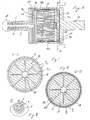
- FIG. 1 shows in a longitudinal section a roller for the thermomechanical treatment of a web-like material, for example a paper web in a paper machine.
- the roll may in particular be a calender roll.
- the roller comprises a roller body with a hollow cylindrical shell 1, a first pin flange 2 and a second pin flange 3, which are fastened to the casing 1 at opposite axial ends.
- the journal flanges 2 and 3 serve to pivot the roll body about an axis of rotation R.
- the journal flange 2 forms the drive flange on which the torque for the rotary drive of the roller is introduced.
- the journal flange 3 serves to supply and discharge a tempering fluid, for example a thermal oil, with which the jacket 1 is heated to a desired temperature for the treatment of the sheet material.
- a distribution system for the tempering fluid is formed inside the shell 1.
- the discharge 5 is obtained by means of a tube inserted into the pin flange 3 as an annular gap between the tube and a surrounding inner surface of the Zapfenflansches 3.
- the discharge 5 could also be obtained with bores extending axially through the pin flange 3.
- the discharge 5 could be formed centrally and the supply 4 surrounding the discharge 5.
- the tempering fluid can be supplied to the distributor system through the feed 4 and can be discharged through the outlet 5.
- To the distribution system include both on the flange pin 3 comprehensive supply and discharge side of the roller as well as on the flange 2 comprehensive drive side each a distributor chamber 6 and a collecting chamber 7 and peripheral tempering 10a and 10b, extending axially over the entire length of the shell 1 extend, at least over the entire length, with which the roller acts on a web to be treated maximum width.
- the temperature control channels 10a and 10b are distributed uniformly around the rotation axis R on the inner peripheral surface of the shell 1.
- the temperature control channels 10a are outflow channels, and the temperature control channels 10b are return flow channels.
- the temperature control channels 10a and 10b are arranged adjacent to one another in the circumferential direction alternately in the circumferential direction, ie, a return flow channel 10b follows in each case one inflow channel 10a and an inflow channel 10a on each return flow channel 10b.
- the two distribution chambers 6 and the two collector chambers 7 are axially bounded by separating structures 8 and 9 and one of the journal flanges 2 and 3, and are also fluidly separated from one another on the supply and discharge side by the separating structure 9 there.
- the separation structures 8 and 9 are circular disk-shaped, each with a serrated outer peripheral edge.
- the separation structures 8 and 9 are arranged at the respective axial end of the shell 1 at a small axial distance from one another and also at a small axial distance from the respective pin flange 2 or 3, so that the distribution spaces 6 and collecting spaces 7 are each cylindrical disk-shaped.
- the separating structures 8 and 9 delimit between them the distributor space 6 and the pin flange 3 with the separating structure 9 the collecting space 7.
- the separating structures 8 and 9 define axially between them the collecting space 7, and the separating structure 9 limited with the pin flange 2, the distribution space. 6
- the tempering fluid is introduced centrally through the feed 4 into the distributor chamber 6 of the supply and discharge side, and flows at the peripheral edge of the axially inner separation structure 8 into the outflow channels 10a.
- the tempering fluid flows through the inflow channels 10a in the axial direction and passes over the outer peripheral edge of the axially opposite inner separation structure 8 in the local collecting space 7, is diverted inwards there in the direction of the axis of rotation R and flows through a central opening of the axially outer separation structure 9 in the temperature control fluid flows through the distributor space 6 of the drive side radially outward and passes over the outer peripheral edge of the separation structure 9 in the return flow 10b, the temperature control flows through the return flow channels 10b in the axial direction, is on the supply and discharge side in the local Collecting chamber 7 collected and flows through the collection chamber 7 and the central discharge 5 back into the external fluid supply system of the roller.
- FIG. 2 shows the roller body in the in FIG. 1 registered cross-section BB.
- the temperature control channels 10a and 10b are radially outwardly of the shell 1, that is limited by the inner peripheral surface of the shell 1, and inwardly of profiles P arranged in the circumferential direction about the rotation axis R side by side on the inner peripheral surface of the shell 1 and with the Mantle 1 are firmly and fluid-tightly joined by welding over their entire axial length.
- the temperature control channels 10a and 10b are each of a single profile P and the shell 1 limited, ie, the jacket 1 and one of the profiles P together form the peripheral wall of the respective temperature control channel 10a or 10b.
- the profiles P are angle profiles, in the exemplary embodiment isosceles L-profiles with a first leg 11 and a second leg 12, which enclose an angle ⁇ of at least substantially 90 °.
- the profiles P are closely spaced next to each other, so that in the circumferential direction next adjacent profiles P are connected by means of a common axially continuous continuous weld 13 with the jacket 1.
- the welds 13 are welded under powder or more preferably electron beam.
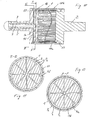
- FIG. 3 shows a peripheral portion of the roller body. To explain the geometric conditions with regard to the preparation of welding, a profile P is shown on the right before the weld is made and in the left half of FIG FIG. 3 a profile P shown after generation of the weld 1.3.
- the legs 11 and 12 form the side walls of the respective profile P limited tempering 10a or 10b, and the jacket 1 forms the outer wall.
- temperature control channels 10a and 10b with a triangular flow cross section are obtained in the exemplary embodiment.
- the profiles P are each attached to the inner edge of their legs 11 and 12 on the inner peripheral surface of the shell 1.
- the free end faces of the legs 11 and 12 are perpendicular to the respective leg 11 or 12 and accordingly at an angle ⁇ of about 45 ° to the inner peripheral surface of the shell 1, ie they close with the inner peripheral surface therefore each an angle ⁇ of about 45 ° and define accordingly with the inner peripheral surface of a wedge-shaped gap, in which the powdery filler material is introduced for the welding process by welding in the hollow shell 1 under powder.
- each next adjacent profiles P are set in a circumferentially small distance from each other to the inner peripheral surface of the shell 1, so that the filler material can penetrate into the space between the shell 1 and the end faces of each next adjacent legs 11 and 12.
- the welds 13 can be formed by chamfering post-processing, such as loops, between the next adjacent legs 11 and 12 as flutes to avoid notch effects.
- FIG. 4 shows a peripheral portion of a modified with respect to the cross section of the temperature control 10a and 10b roller body 1.
- the modification is that the return flow 10b compared to Hinströmkanälen 10a have a smaller flow area, so that the tempering fluid flows through the return flow channels 10b at a greater flow rate than the Hinströmkanäle 10a and in this way the temperature difference between the tempering fluid and the jacket 1 already reduced in the return flow passages 10b is at least partially compensated.
- the inflow passages 10a correspond to the inflow passages 10a of FIG Figures 2 and 3
- the profiles of the Hinströmkanäle 10a are denoted by P a and the profiles of the return channels 10b with P b.
- the profiles P b are also angle profiles, in the exemplary embodiment L-profiles with at least substantially mutually perpendicular legs 11 and 12-
- the profiles P b differ from the profiles P a only by the radial height or the length of the legs 11 and 12th , which is reduced in the profiles P b with respect to the profiles P a . Further differences exist to the profiles P of Figures 2 and 3 Not. Due to the reduced leg length or radial height, the inflow channels 10a move closer to one another in the circumferential direction. As a result, due to the reduced radial height of the return flow channels 10b, space is still obtained for the joining tool, in the exemplary embodiment the welding tool. The accessibility of the joining area and the verifiability of the welds 13 are further improved.
- FIG. 5 shows a peripheral portion of the roller body 1 with a different modification with respect to the arrangement of profiles P.
- All profiles P correspond to the profiles P in the embodiment of the FIG. 3 and the profiles P a of the embodiment of FIG. 4 ,
- Return flow and return passages 10a and 10b are thus again as in the embodiment of FIG. 3 formed by respective profiles P in the same cross section.
- the legs 11 and 12 of each profile P are connected by means of their own separate connection seam 14 with the roller body 1.
- the profiles P are correspondingly widely spaced from their respective two adjacent profiles P in the circumferential direction of the roller body 1, so that the connecting seams 14 per leg 11 and 12 can be produced individually as a V-seam. Due to the increased distance between each next adjacent profiles P accessibility in welding is improved over the other two examples.
- the embodiment corresponds to the FIG. 5 the embodiment of the FIG. 3 ,
- the profiles P and P a and P b can be welded together in a particularly preferred embodiments by means of energy-beam welding, in particular electron beam welding, with the jacket 1 and preferably also in pairs by being arranged in the circumferential direction close to each other, where they can also contact each other laterally ,
- the profiles P or P a and P b may be as in the FIGS. 3 to 5 represented with in each case an inner edge on the front side of the side walls 11 and 12 are arranged in a linear contact with the inner surface of the shell 1.
- the profile legs 11 and 12 can also be flattened on their end faces in order to obtain surface contact with the jacket 1. They can also be rounded at the ends.
- the separation structures 8 correspond in cross section at the same profiles P in the FIG. 2 free inner cross-section of the shell 1.
- the two axially inner separating structures 8 seal the distribution chamber 6 on the inlet and outlet side and the collecting chamber 7 on the opposite side axially inwards. They have a closed to the peripheral edge circular cross-section and are jagged at its outer peripheral edge corresponding to the cross-sectional shape of the profiles P and in the modified version of the profiles P a and P b , and with the profiles P and in the modified embodiment, the profiles P a and P. b firmly and fluid-tightly connected.
- the axially outer separating structures 9 differ from the axially inner separating structures 8, in particular in the course of their outer circumference, since they are penetrated only by the profiles P or P b of the return flow channels 10b. In other words, in the case of the outer separating structures 9, only the passages for the profiles P and P a for the inflow passages 10 a are missing. Furthermore, a central opening is provided in each case in the outer separating structures 9 in the exemplary embodiment, on the inlet and outlet side for the inflowing and on the opposite side for the temperature control fluid to be supplied to the return flow channels 10b. After axially outside the collecting space 7 on the supply and Abriosseite and the distribution chamber 6 on the opposite side of the respective pin flange 2 or 3 completed.
- both axial outer spaces 6 and 7 could be formed in the respective journal flange 2 or 3.
- both chambers 6 and 7 may be formed in the respective journal flange 2 or 3 at one axial end or at both axial ends.
- FIG. 6 shows a roller with the profile system of the embodiment of FIG. 4 and a distribution and collection system formed in the journal flanges 2 and 3.
- the FIGS. 7 and 8 show the in FIG. 6 registered cross sections CC and DD.
- FIG. 9 shows a view of the supply and discharge side of the roller, which in the FIGS. 6 and 9 is denoted by A.
- the discharge 5 is formed by a plurality of evenly distributed around the central feed 4 arranged axial feed channels in the journal flange 3.
- the fluid is supplied on the supply and discharge side through the central feed 4, passed in the spigot flange 2 via connecting channels 4a outwardly into a peripheral serving as a distributor chamber 16 annular channel, the connecting channels 4a and the distribution chamber 16 are formed in the journal flange 3.
- the outflow channels 10a connect the distributor chamber 16 with a collection space 17, likewise formed as an annular channel, which is formed in the journal flange 2 at the opposite end of the roller. From this collecting space 17 lead connecting channels 4b in a central space 18 in the journal flange 2. The space 18 is connected via further connecting channels 4c, which are also formed in the journal flange 2, with a second distribution chamber 16. The second distributor chamber 16 is also formed in the journal flange 2 as an annular channel. The distributor chamber 16 distributes the tempering fluid into the return flow channels 10b, which open into a collecting space 17, which connects the return flow channels 10b to the discharge 5 via connection channels 4d on the inlet and outlet side.
- the collecting space 17 of the supply and discharge side is also formed in the journal flange 3 as an annular channel.
- the connecting channels 4a, 4b, 4c and 4d are each formed in the journal flange 2 or 3 as radial bores which connect the distributor and collecting chambers 16 and 17 in the respective journal flange 2 or 3 with the feed 4 or the discharge 5 or the space 18.
- FIG. 10 shows a further roller with the configuration of the profiles P a and P b of FIG. 4 and a distribution and collection system for the tempering fluid formed in the journal flanges 2 and 3.
- the inlet and outlet side corresponds to the embodiment of FIGS. 6 to 9 , Only the opposite end of the roller is compared to the embodiment of FIGS. 6 to 9 modified by there no distributor space, but only a collecting space 17 in the form of a circumferential, receding in itself annular channel in the pin 2 is formed. This collecting space 17 is completed radially outward from the roller body 1, as well as for the distribution and collection spaces 16 and 17 of the embodiment of FIGS. 6 to 9 the case is.
- the fluid is supplied as there through the central feed 4, passed through the connecting channels 4a to the outside in the distribution chamber 16 of the supply and discharge side and from there into the Hinströmkanäle 10a.
- the tempering fluid flowing through the inflow channels 10a is collected on the opposite side in the collecting space 17 and flows back through the return flow channels 10b to the inlet and outlet side, is collected in the local collecting space 17 and recirculated via the connection channels 4d and the outlet 5 for the purpose of temperature control.
- To the distribution chamber 16 of the supply and discharge side of both embodiments is still to be noted that all Hinströmkanäle 10a are connected to this distribution chamber 16, all return flow channels 10b but are guided through this distribution chamber 16 through to the collecting space 17 of the supply and discharge side.
- FIG. 13 shows a section of a roll with a welded distribution and collection system. Shown is merely a section of the roller end with the pin flange 3.
- the distribution and collection system is obtained with connecting pipes and distribution rings, which are welded together.
- the connecting pipes form connecting channels 4 a functional as in the embodiments of the FIGS. 6 to 12 ,
- the connecting pipes are therefore also designated by 4a.
- a distributor ring 16 which is welded to the tubes 40 and the roller body 1 and the profiles P. For simplicity, it is assumed that the arrangement of the profiles P in the embodiment of the FIG. 3 equivalent.
- the pin flange 3 serves both the supply and the discharge of the tempering fluid
- a further distributor pot can be arranged in the distributor pot 19, into which welded tubes for forming the connection channels 4 d of the embodiments of FIGS FIGS. 6 to 12 to lead.
- the tempering fluid can also be discharged through the journal flange 2 on the opposite side. In such embodiments, only the distribution system and on the opposite side only the collection system are thus formed on the side of the journal flange 3.
- the collection system would correspond structurally to the distribution system of the feed side, denoted by 20 is a pressure compensation gap.
- the distribution and collection system is preferably formed either only with cutting discs or in the journal flanges molded distribution or collection chambers or only as a welded distribution and collection system, mixed forms of different distribution and collection systems should not be excluded, such as the formation of a distributor Collecting space at one end of the roll by means of one or more cutting discs and the formation of a distributor space or collecting space at the other end of the roll in the local pin flange.
- the roll end of the supply and discharge side according to the embodiment of FIG. 1 and the opposite roll end of the embodiment of FIG. 6 , of the FIG. 10 or the FIG. 13 be formed accordingly.
- the roller end with the pin flange 2 of the FIG. 6 for example, against the welded system of FIG. 13 or the separating disk system at the journal flange of FIG. 1 be replaced, to name just a few examples.
- FIG. 14 shows a roll shell, which is joined from ring shell parts 1a, 1b and 1c.
- the ring shell parts 1a, 1b and 1c are equal to each other. They extend in the circumferential direction about the axis of rotation R over an angle ⁇ of 120 ° and abut each other with their axially extending, parallel to the axis of rotation R facing end sides. In the joint areas, they are each joined in pairs by means of an axially continuous 1-weld seam 1d.
- the structure of the roll shell of ring shell parts 1 a, 1 b and 1 c facilitates the placement and joining of the profiles P, alternatively the profiles P a and P b , on the shell inner surfaces of the Ring shell parts 1a, 1b and 1c.
- the ring shell parts 1a, 1b and 1c have cylindrical inner and outer peripheral surfaces.
- the profiles P are arranged on the inner surface of the respective annular shell part 1a or 1b or 1c and joined by electron beam welding to the annular shell part 1a, 1b or 1c.
- the profiles P alternatively the profiles P a and P b or other types of profiles, arranged so close to each other in the circumferential direction that the next adjacent side walls are welded to the respective ring shell part 1a, 1b or 1c with the same energy beam.
- several energy beams can be moved axially along the profiles P in the welding direction at the same time and one of the connecting seams can be generated continuously per energy beam. Particularly preferred four successive circumferentially connecting seams are generated.
- the preferred arrangement close to each other are connecting seams 13, in the case of an arrangement of the profiles P or P a and P b at a distance around connecting seams 14 (FIG. FIG. 5 ).
- the profiles P or P a and P b as in the FIGS. 3 and 4 or preferably be arranged even closer together in the circumferential direction.
- the ring shell parts 1a, 1b and 1c are fixed either in pairs or simultaneously all three relative to each other in a joining position and the connecting seams 1d produced.
- the connecting seams 1d are, as stated, preferably also produced by means of electron beam welding.
- the arrangement of the profiles is preferably such that during the production of the connecting seams 1d, one of the connecting seams for the profiles is also produced simultaneously.
- FIG. 14 represented at the two free circumferential ends of the annular shell parts 1a, 1b and 1c each one of the profiles with one of its two side walls leak, so that the relevant seam for the profile comes to rest radially in overlap with the respective seam 1d.
- FIG. 15 shows an assembled of three ring shell parts 1a, 1b and 1c axial segment for an axially longer roll shell, for example, for the roll shells 1 of FIGS. 16 and 18 ,
- the ring shell parts 1a, 1b and 1c can already form a roll shell 1 alone.
- FIG. 16 shows a roll shell 1, which consists of two axial segments corresponding to the segment of FIG. 15 is joined by the two segments are joined together by creating a circumferential seam 1e.
- FIG. 17 shows a further joining example of a roll shell 1 of ring shell parts 1a, 1b and 1c. In the axial direction, this roll shell 1 has four of these ring shell parts side by side.
- FIG. 17 shows that the annular shell parts 1a, 1b and 1c for joining the composite roll shell 1 in a first step, for example, in groups of three to a respective shell segment corresponding to FIG. 15 joined and then by means of connecting seams 1e axially pairs can be joined together.
- FIG. 17 shows alternatively that the ring shell parts 1a, 1b and 1c can be joined together in quasi-free sequence and not in a first step in each case segments accordingly FIG. 15 produced and then must be joined axially abutting each other. The joining of first segments according to the FIG. 15 and the subsequent assembly of such segments is however preferred.
- FIG. 18 shows a composite of a plurality of axial segments roll shell 1, wherein each of these segments consists of the ring shell parts 1a, 1b and 1c.
Landscapes
- Rolls And Other Rotary Bodies (AREA)
- Heat Treatment Of Articles (AREA)
Claims (15)
- Corps de cylindre pour le traitement d'un matériau en bande, comprenanta) un manteau (1) etb) des profilés (P; Pa, Pb) répartis autour d'un axe de rotation (R) du corps de cylindre sur une surface périphérique intérieure du manteau (1) et formant avec le manteau (1) des canaux au moins essentiellement axiaux (10a, 10b) pour un fluide de maintien de température,c) le manteau (1) formant une paroi extérieure et les profilés (P; Pa, Pb) une paroi extérieure et les parois latérales (11, 12) des canaux (10a, 10b),d) chacune des parois latérales (11, 12) étant reliée au manteau (1) au moyen d'un cordon de liaison (13; 14) respectif formé en continuité de matière,
caractérisé en ce quee) jusqu'au cordon de liaison (13), les parois latérales (11, 12) de profilés immédiatement voisins (P; Pa, Pb) présentent en coupe transversale une inclinaison inférieure à 90° par rapport au manteau (1) de sorte qu'elles s'éloignent l'une de l'autre à partir du cordon de liaison (13; 14). - Corps de cylindre selon la revendication 1, caractérisé en ce que les profilés (P; Pa, Pb) présentent chacun une première aile (11) et une deuxième aile (12) qui constituent les parois latérales (11, 12), qui s'étendent en direction d'un côté ouvert du profilé (P; Pa, Pb) et se terminent par chacun de leurs côtés frontaux dans l'un des cordons de liaison (13; 14).
- Corps de cylindre selon l'une des revendications précédentes, caractérisé en ce que les profilés (P; Pa, Pb) sont des profilés coudés, par exemple en L ou en V.
- Corps de cylindre selon l'une des revendications précédentes, caractérisé en ce que les parois latérales (11, 12) pointent en direction des surfaces intérieures du manteau (1) et leur côté frontal dirigé vers la surface intérieure du manteau (1) est formé de telle sorte que lors de la réalisation des cordons de liaison (13; 14), elles soient en contact avec la surface intérieure du manteau (1) par leur surface ou uniquement linéairement par un chant.
- Corps de cylindre selon l'une des revendications précédentes, caractérisé en ce qu'avant la création du cordon de liaison (13; 14) respectif, les parois latérales (11, 12) présentent chacune une surface frontale tournée vers le manteau (1) et qui forme un angle (ß) supérieur à 0° et inférieur à 90° avec le manteau (1).
- Corps de cylindre selon l'une des revendications précédentes, caractérisé en ce que les cordons de liaison (13; 14) sont des cordons de soudure, des cordons de brasure ou des cordons collés, soudés par exemple à la poudre, sous gaz protecteur, au moyen d'un rayon laser ou d'un faisceau d'électrons et en ce que les extrémités des parois latérales (11, 12) de profilés (P; Pa, Pb) immédiatement voisins sont liées au manteau (1) au moyen d'un même cordon de liaison (13) ou de cordons de liaison (14) respectifs distincts.
- Corps de cylindre selon l'une des revendications précédentes, caractérisé en ce que des garnitures réduisant de la section transversale d'écoulement ou provoquant des turbulences sont disposées dans au moins une partie des profilés (P; Pa, Pb) ou en ce que la section transversale d'au moins une partie des profilés (P; Pa, Pb) présente un contour qui varie dans la direction axiale ou dont la hauteur radiale varie.
- Corps de cylindre selon l'une des revendications précédentes, caractérisé en ce que le manteau (1) est composé de parties de coquille annulaire (1a, 1b, 1c) qui s'étendent dans le sens de la circonférence sur un angle (γ) maximal de 180 ° et en ce que les parties de coquille annulaire (1a, 1b, 1c) sont jointes les unes aux autres au moyen de cordons de liaison (1d) qui s'étendent axialement.
- Corps de cylindre selon l'une des revendications précédentes, caractérisé en ce que(i) un espace de répartition (6) ou un espace de collecte (7) par lesquels le fluide d'ajustement de température est réparti dans au moins une partie des canaux (10a, 10b) ou collecté au départ d'au moins une partie des canaux (10a, 10b) sont prévus sur une extrémité axiale du manteau (1),(ii) une structure de séparation (8, 9) en forme de disque est disposée à une extrémité dans le manteau (1),(iii) les profilés (P; Pa, Pb) ou uniquement un groupe de profilés (P; Pa, Pb) s'étendent jusque dans la structure de séparation (8, 9) ou débordent à travers cette dernière jusque dans l'espace de répartition (6) ou l'espace de collecte (7) et(iv) le long de son bord périphérique extérieur, la structure de séparation (8, 9) est reliée de façon étanche aux profilés (P; Pa, Pb) ou uniquement au groupe de profilés (P; Pa, Pb) en entourant l'axe de rotation (R).
- Corps de cylindre selon la revendication précédente, caractérisé en ce qu'une autre telle structure de séparation (8, 9) en forme de disque est disposée à l'extrémité, un des disques de séparation (8, 9) étant traversé par le premier et le deuxième groupe de profilés (P; Pa, Pb) et l'autre disque de séparation (6) uniquement par l'un des groupes.
- Corps de cylindre selon l'une des revendications précédentes, caractérisé en ce qu'un premier groupe de profilés (Pa, Pb) présente une grande section transversale ou est radialement élevé et un deuxième groupe de profilés (Pa, Pb) présente une section transversale proportionnellement plus petite ou est radialement plat, au moins l'un des profilés (Pb) du deuxième groupe étant disposé entre deux profilés (Pa) du premier groupe dans le sens de la circonférence autour de l'axe de rotation (R).
- Corps de cylindre selon l'une des revendications précédentes, caractérisé en ce que(i) un premier groupe de profilés (Pa, Pb) constitue des canaux d'amenée (10a) et un deuxième groupe de profilés (Pa, Pb) des canaux de retour (10b),(ii) un espace de répartition (6; 16) relié aux canaux d'amenée (10a) et facultativement un espace de collecte (7; 17) relié aux canaux de retour (10b) sont prévus sur une extrémité axiale du corps de cylindre, de préférence axialement à l'intérieur du manteau (1) et(iii) un espace de collecte (7 ; 17) relié aux canaux d'amenée (10a) et facultativement aux canaux de retour (10b) est prévu sur l'autre extrémité axiale du corps de cylindre, de préférence axialement à l'intérieur du manteau (1).
- Corps de cylindre selon l'une des revendications 1 à 11, caractérisé en ce qu'un flasque de tourillon gauche et un flasque de tourillon droit (2, 3) sont reliés au corps de cylindre (1), un espace annulaire de répartition ou un espace annulaire de collecte (16, 17) étant formés à la périphérie extérieure ou à proximité de la périphérie extérieure par au moins l'un des flasques de tourillon (2, 3).
- Procédé de fabrication d'un corps de cylindre selon l'une des revendications précédentes, dans lequel :a) les profilés (P; Pa, Pb) sont disposés sur la surface intérieure de parties de coquille annulaire (1a, 1b, 1c) et sont assemblés aux parties de coquille annulaire (1a, 1b, 1c) par formation des cordons de liaison (13; 14) etb) les parties de coquille annulaire (1a, 1b, 1c) assemblées aux profilés (P; Pa, Pb), qui s'étendent chacune sur un angle (γ) maximal de 180°, dans le sens de la circonférence, sont assemblées pour former le manteau (1).
- Procédé selon la revendication précédente, caractérisé en ce que les profilés (P; Pa, Pb) sont reliés aux parties de coquille annulaire (1a, 1b, 1c) par soudure à faisceau d'énergie, plusieurs profilés (P; Pa, Pb), par exemple des profilés (P; Pa, Pb), étant reliés ensemble à au moins une des parties de coquille annulaire (1a, 1b, 1c) en groupes d'au moins deux et d'au maximum six, par soudage au mayen de plusieurs faisceaux d'énergie et de préférence au moyen d'un faisceau énergétique subdivisé en faisceaux partiels.
Applications Claiming Priority (1)
| Application Number | Priority Date | Filing Date | Title |
|---|---|---|---|
| DE102007026386A DE102007026386B4 (de) | 2007-06-06 | 2007-06-06 | Walzenkörper mit Profilkanälen für ein Temperierfluid |
Publications (3)
| Publication Number | Publication Date |
|---|---|
| EP2000586A2 EP2000586A2 (fr) | 2008-12-10 |
| EP2000586A3 EP2000586A3 (fr) | 2010-04-07 |
| EP2000586B1 true EP2000586B1 (fr) | 2012-08-08 |
Family
ID=39764913
Family Applications (1)
| Application Number | Title | Priority Date | Filing Date |
|---|---|---|---|
| EP08157698A Not-in-force EP2000586B1 (fr) | 2007-06-06 | 2008-06-05 | Corps de cylindre munis de profilés formant des canaux pour un fluide d'ajustement de température |
Country Status (3)
| Country | Link |
|---|---|
| US (1) | US20080305937A1 (fr) |
| EP (1) | EP2000586B1 (fr) |
| DE (1) | DE102007026386B4 (fr) |
Families Citing this family (2)
| Publication number | Priority date | Publication date | Assignee | Title |
|---|---|---|---|---|
| DE102006042752A1 (de) * | 2006-09-12 | 2008-03-27 | Shw Casting Technologies Gmbh | Verfahren zur Herstellung eines Rohrkörpers für die Weiterbearbeitung zu einer Walze |
| DE102012104464A1 (de) * | 2012-05-23 | 2013-11-28 | Gapcon Gmbh | Temperierbarer Zylinder zur Behandlung von flächigen Materialien |
Family Cites Families (7)
| Publication number | Priority date | Publication date | Assignee | Title |
|---|---|---|---|---|
| US2932091A (en) | 1956-10-08 | 1960-04-12 | Day George Donald | Heated shell drum dryers |
| US2936158A (en) * | 1958-12-24 | 1960-05-10 | Kentile Inc | Heat exchange rolls |
| US6250622B1 (en) * | 1999-05-20 | 2001-06-26 | Heidelberger Druckmaschinen Aktiengesellschaft | Cylinder assembly for a folding apparatus of a rotary printing press |
| ATE351941T1 (de) * | 2000-03-14 | 2007-02-15 | Walzen Irle Gmbh | Rotierbare walze |
| DE10239559B4 (de) | 2002-08-28 | 2016-09-29 | Shw Casting Technologies Gmbh | Walze für die thermomechanische Behandlung eines bahnförmigen Mediums |
| FI114563B (fi) * | 2003-01-29 | 2004-11-15 | Metso Paper Inc | Putkitela paperikonetta varten |
| DE102005043734A1 (de) * | 2005-09-14 | 2007-03-22 | Voith Patent Gmbh | Beheizbarer Zylinder insbesondere zur Aufheizung einer Papierbahn |
-
2007
- 2007-06-06 DE DE102007026386A patent/DE102007026386B4/de not_active Expired - Fee Related
-
2008
- 2008-06-05 EP EP08157698A patent/EP2000586B1/fr not_active Not-in-force
- 2008-06-05 US US12/133,894 patent/US20080305937A1/en not_active Abandoned
Also Published As
| Publication number | Publication date |
|---|---|
| EP2000586A2 (fr) | 2008-12-10 |
| DE102007026386B4 (de) | 2012-09-27 |
| US20080305937A1 (en) | 2008-12-11 |
| DE102007026386A1 (de) | 2008-12-11 |
| EP2000586A3 (fr) | 2010-04-07 |
Similar Documents
| Publication | Publication Date | Title |
|---|---|---|
| DE2744263C3 (de) | Röhrenwärmeaustauscher | |
| DE69608109T2 (de) | Sieb und verfahren zur herstellung | |
| EP0772018B1 (fr) | Echangeur de chaleur pour le refroidissement de gaz d'échappement | |
| DE60203721T2 (de) | Verfahren zur herstellung einer versetzten wellenförmigen rippe | |
| DE3604677C2 (fr) | ||
| DE2331563C3 (de) | Waermetauscher | |
| EP1836346B1 (fr) | Dispositif et procede de production et/ou de transformation d'une bande de matiere fibreuse | |
| EP2250457B1 (fr) | Echangeur thermique à plaque, plaque d échangeur thermique et leur procédé de fabrication | |
| WO2021180355A1 (fr) | Procédé de production de joints soudés entre des tubes internes et des plaques porte-tube d'un faisceau tubulaire pour un échangeur de chaleur à faisceau tubulaire de type produit à produit au moyen d'un dispositif auxiliaire, et dispositif auxiliaire conçu pour un tel procédé de production | |
| EP2000586B1 (fr) | Corps de cylindre munis de profilés formant des canaux pour un fluide d'ajustement de température | |
| EP0437825B1 (fr) | Echangeur de chaleur avec plaque d'extrémité et manchon de raccord | |
| DE102015118163A1 (de) | Windenergieturm | |
| DE102005000794A1 (de) | Vorrichtung und Verfahren zur Herstellung und/oder Veredelung einer Faserstoffbahn | |
| DE69715919T2 (de) | Plattenwärmetauscher | |
| DE4019991A1 (de) | Kolonnenkoerper zur aufnahme von plattenwaermetauschern | |
| WO2009003784A2 (fr) | Bague d'usure pour pompes à béton | |
| DE9107311U1 (de) | Schweißmuffe | |
| DE202007006464U1 (de) | Heizplatte | |
| DE2308317B2 (de) | Waermetauscher grosser abmessung fuer den betrieb bei hohen temperaturen und druecken | |
| EP2098812A2 (fr) | Radiateur plat de chauffage ou de refroidissement et procédé de fabrication d'un tel radiateur | |
| DE3332159C2 (de) | Verfahren zum Herstellen eines Plattenwärmetauschers | |
| DE1962953C3 (de) | Absperrschiebergehäuse mit eingeschweißten, als Dichtsitze ausgebildeten, die Kühlkammern begrenzenden Winkelstücken | |
| EP1573232A1 (fr) | Stator pour convertisseur de couple hydrodynamique | |
| EP0994320B1 (fr) | Radiateur avec au-moins deux tubes plats superposés | |
| EP4031810B1 (fr) | Séparateur de liquide de générateur de vapeur et procédé pour le fabriquer |
Legal Events
| Date | Code | Title | Description |
|---|---|---|---|
| PUAI | Public reference made under article 153(3) epc to a published international application that has entered the european phase |
Free format text: ORIGINAL CODE: 0009012 |
|
| AK | Designated contracting states |
Kind code of ref document: A2 Designated state(s): AT BE BG CH CY CZ DE DK EE ES FI FR GB GR HR HU IE IS IT LI LT LU LV MC MT NL NO PL PT RO SE SI SK TR |
|
| AX | Request for extension of the european patent |
Extension state: AL BA MK RS |
|
| PUAL | Search report despatched |
Free format text: ORIGINAL CODE: 0009013 |
|
| AK | Designated contracting states |
Kind code of ref document: A3 Designated state(s): AT BE BG CH CY CZ DE DK EE ES FI FR GB GR HR HU IE IS IT LI LT LU LV MC MT NL NO PL PT RO SE SI SK TR |
|
| AX | Request for extension of the european patent |
Extension state: AL BA MK RS |
|
| RIC1 | Information provided on ipc code assigned before grant |
Ipc: D21F 5/02 20060101ALI20100301BHEP Ipc: D21G 1/02 20060101AFI20100301BHEP |
|
| 17P | Request for examination filed |
Effective date: 20100511 |
|
| 17Q | First examination report despatched |
Effective date: 20100610 |
|
| RIC1 | Information provided on ipc code assigned before grant |
Ipc: D21G 1/02 20060101AFI20100901BHEP Ipc: D21F 5/02 20060101ALI20100901BHEP |
|
| AKX | Designation fees paid |
Designated state(s): AT FI GB IT SE |
|
| GRAP | Despatch of communication of intention to grant a patent |
Free format text: ORIGINAL CODE: EPIDOSNIGR1 |
|
| REG | Reference to a national code |
Ref country code: DE Ref legal event code: 8566 |
|
| RBV | Designated contracting states (corrected) |
Designated state(s): AT DE FI GB IT SE |
|
| GRAS | Grant fee paid |
Free format text: ORIGINAL CODE: EPIDOSNIGR3 |
|
| RBV | Designated contracting states (corrected) |
Designated state(s): AT DE FI GB IT SE |
|
| GRAA | (expected) grant |
Free format text: ORIGINAL CODE: 0009210 |
|
| AK | Designated contracting states |
Kind code of ref document: B1 Designated state(s): AT DE FI GB IT SE |
|
| REG | Reference to a national code |
Ref country code: GB Ref legal event code: FG4D Free format text: NOT ENGLISH |
|
| REG | Reference to a national code |
Ref country code: AT Ref legal event code: REF Ref document number: 569869 Country of ref document: AT Kind code of ref document: T Effective date: 20120815 |
|
| REG | Reference to a national code |
Ref country code: SE Ref legal event code: TRGR |
|
| REG | Reference to a national code |
Ref country code: DE Ref legal event code: R096 Ref document number: 502008007879 Country of ref document: DE Effective date: 20120927 |
|
| PLBE | No opposition filed within time limit |
Free format text: ORIGINAL CODE: 0009261 |
|
| STAA | Information on the status of an ep patent application or granted ep patent |
Free format text: STATUS: NO OPPOSITION FILED WITHIN TIME LIMIT |
|
| 26N | No opposition filed |
Effective date: 20130510 |
|
| REG | Reference to a national code |
Ref country code: DE Ref legal event code: R097 Ref document number: 502008007879 Country of ref document: DE Effective date: 20130510 |
|
| PG25 | Lapsed in a contracting state [announced via postgrant information from national office to epo] |
Ref country code: SE Free format text: LAPSE BECAUSE OF NON-PAYMENT OF DUE FEES Effective date: 20130606 |
|
| REG | Reference to a national code |
Ref country code: SE Ref legal event code: EUG |
|
| GBPC | Gb: european patent ceased through non-payment of renewal fee |
Effective date: 20130605 |
|
| PG25 | Lapsed in a contracting state [announced via postgrant information from national office to epo] |
Ref country code: FI Free format text: LAPSE BECAUSE OF NON-PAYMENT OF DUE FEES Effective date: 20130605 |
|
| PG25 | Lapsed in a contracting state [announced via postgrant information from national office to epo] |
Ref country code: GB Free format text: LAPSE BECAUSE OF NON-PAYMENT OF DUE FEES Effective date: 20130605 |
|
| PG25 | Lapsed in a contracting state [announced via postgrant information from national office to epo] |
Ref country code: IT Free format text: LAPSE BECAUSE OF NON-PAYMENT OF DUE FEES Effective date: 20130605 |
|
| REG | Reference to a national code |
Ref country code: AT Ref legal event code: MM01 Ref document number: 569869 Country of ref document: AT Kind code of ref document: T Effective date: 20130605 |
|
| PG25 | Lapsed in a contracting state [announced via postgrant information from national office to epo] |
Ref country code: AT Free format text: LAPSE BECAUSE OF NON-PAYMENT OF DUE FEES Effective date: 20130605 |
|
| PGFP | Annual fee paid to national office [announced via postgrant information from national office to epo] |
Ref country code: DE Payment date: 20150619 Year of fee payment: 8 |
|
| REG | Reference to a national code |
Ref country code: DE Ref legal event code: R119 Ref document number: 502008007879 Country of ref document: DE |
|
| PG25 | Lapsed in a contracting state [announced via postgrant information from national office to epo] |
Ref country code: DE Free format text: LAPSE BECAUSE OF NON-PAYMENT OF DUE FEES Effective date: 20170103 |