EP2000701A1 - Vorrichtung zur Reduzierung der azyklischen Bewegungen eines Schwungrads - Google Patents
Vorrichtung zur Reduzierung der azyklischen Bewegungen eines Schwungrads Download PDFInfo
- Publication number
- EP2000701A1 EP2000701A1 EP08157015A EP08157015A EP2000701A1 EP 2000701 A1 EP2000701 A1 EP 2000701A1 EP 08157015 A EP08157015 A EP 08157015A EP 08157015 A EP08157015 A EP 08157015A EP 2000701 A1 EP2000701 A1 EP 2000701A1
- Authority
- EP
- European Patent Office
- Prior art keywords
- flywheel
- recess
- connecting piece
- acyclisms
- inertia
- Prior art date
- Legal status (The legal status is an assumption and is not a legal conclusion. Google has not performed a legal analysis and makes no representation as to the accuracy of the status listed.)
- Withdrawn
Links
- 239000000463 material Substances 0.000 claims abstract description 4
- 125000002015 acyclic group Chemical group 0.000 claims description 4
- 239000000314 lubricant Substances 0.000 abstract 1
- 230000001133 acceleration Effects 0.000 description 3
- 238000002485 combustion reaction Methods 0.000 description 3
- 230000000694 effects Effects 0.000 description 3
- 230000007423 decrease Effects 0.000 description 2
- 238000004519 manufacturing process Methods 0.000 description 1
- 230000010355 oscillation Effects 0.000 description 1
- 239000007858 starting material Substances 0.000 description 1
Images
Classifications
-
- F—MECHANICAL ENGINEERING; LIGHTING; HEATING; WEAPONS; BLASTING
- F16—ENGINEERING ELEMENTS AND UNITS; GENERAL MEASURES FOR PRODUCING AND MAINTAINING EFFECTIVE FUNCTIONING OF MACHINES OR INSTALLATIONS; THERMAL INSULATION IN GENERAL
- F16F—SPRINGS; SHOCK-ABSORBERS; MEANS FOR DAMPING VIBRATION
- F16F15/00—Suppression of vibrations in systems; Means or arrangements for avoiding or reducing out-of-balance forces, e.g. due to motion
- F16F15/10—Suppression of vibrations in rotating systems by making use of members moving with the system
- F16F15/14—Suppression of vibrations in rotating systems by making use of members moving with the system using masses freely rotating with the system, i.e. uninvolved in transmitting driveline torque, e.g. rotative dynamic dampers
- F16F15/1407—Suppression of vibrations in rotating systems by making use of members moving with the system using masses freely rotating with the system, i.e. uninvolved in transmitting driveline torque, e.g. rotative dynamic dampers the rotation being limited with respect to the driving means
- F16F15/145—Masses mounted with play with respect to driving means thus enabling free movement over a limited range
Definitions
- the present invention relates to a device for reducing acyclisms of a flywheel.
- the invention applies more particularly to the reduction of low-speed acyclisms of internal combustion engines.
- crankshaft rotation speed when the engine is idling is justified by the search for a limitation of pollution and consumption of vehicles in urban areas.
- the principle of such a device for reducing acyclisms is as follows.
- one or more pendulum elements which have a degree of freedom in the direction of rotation of the steering wheel.
- said pendular elements acquire a kinetic moment which is mainly a function of the mass m of the pendulum elements and the distance R from their point of connection on the steering wheel to the axis of rotation of the steering wheel.
- the pendulum elements transfer to the steering wheel, by inertia effect, a kinetic moment that is added to that of the steering wheel and thus compensates for the slowdown of the rotation of the steering wheel.
- the inertia of the pendulum elements results in a transfer to the steering wheel of a kinetic moment that retreats to that of the steering wheel and offsets the acceleration of the steering wheel rotation.
- the value of the additional positive or negative kinetic moment depends on the length L of the pendulum equivalent to the pendulum elements.
- the response time of a pendulum element to an acyclism is determined by the three parameters defined above, namely the mass m and the distances R and L. Also, these three parameters are advantageously chosen so as to match the natural frequency of oscillation of the pendulum elements to major harmonics of the acyclisms, which makes particularly effective the compensation effect of the pendulum device for reducing acyclisms.
- the major harmonic has a frequency corresponding to twice the speed of rotation.
- Such an engine equipped with a pendulum device tuned for example on the harmonic H2 can combat all of this harmonic and can turn this regime without annoying irregularities and with a flywheel lightened compared to those used before.
- the production of the pendulum elements and their means of connection to the flywheel can be very varied.
- French patent application no. 2,781,031 proposes a system of movable weights inside circular recesses regularly distributed to the periphery of the flywheel.
- the pendulum element is an oscillating mass connected to the flywheel by a pivoting connection constituted by an axis passing through a first recess formed in the flywheel and a second recess formed in said oscillating mass.
- the two recesses are bores whose diameter is greater than the diameter of the connecting axis so as to allow relative movement of the axis inside the bores.
- this last embodiment has a drawback related to the nature of the contact between the connecting pins and the bores. Indeed, this contact is linear, that is to say that it only carries a generatrix cylindrical surfaces constituting the axis and the bores. It therefore offers very little surface to resume the centrifugal force applied to the mass of the pendulum element. However, this type of effort can become very important when the mass, the speed of rotation and the distance R become sufficiently large.
- an object of the present invention is to provide a device for reducing acyclisms of a flywheel, said device comprising at least one pendular element comprising at least one recess, and a connecting piece between said flywheel. inertia and said pendular element, disposed inside said recess, which would limit the centrifugal forces on said connecting piece and on the pendulum element.
- said connecting piece has a profile capable of making a surface contact with said recess.
- the contact surface between the pendular element and the connecting piece being larger, it limits the pressures applied by the parts on each other.
- the invention provides that, said recess comprising a circular-shaped contact zone, said connecting piece has a circular shape profile conjugate with the circular shape of said contact zone of the recess.
- said connecting piece is made of a self-lubricating material. This arrangement reduces friction between the parts at the contact surface.
- the invention also relates to an engine of a motor vehicle whose mobile assembly comprises a shaft associated with a steering wheel provided with an acyclic reduction device as defined above.
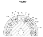
- the figure 1 is a front view of an acyclic reduction device according to the invention.
- flywheel 10 for attachment to one end of the crankshaft of an internal combustion engine.
- This flywheel 10 has a device for reducing the motor acyclisms when idling.
- the device for reducing acyclisms comprises at least one pendular element 20 of mass m having here two recesses 21, 22. Furthermore, two connecting pieces 11, 12 are pivotally mounted respectively about axes 31, 32 which , in the embodiment of the figure 1 , are pins embedded in the steering wheel 10 or additional parts coming together in the body of the steering wheel. The parts 11, 12 can therefore rotate freely about the respective axis 31, 32 so as to accompany the relative translational movement of the pendular element 20 relative to the flywheel 10.
- the connecting pieces 11, 12 are respectively disposed inside the recesses 21, 22, so that, during an acceleration or slowing down of the speed of rotation of the crankshaft, the pendulum element 20 can communicate with the flying 10 a kinetic moment of acyclic compensation. This transfer results from the rotational inertia of the pendular element 20 around the axis of the flywheel 10 and the relative translational movement effected by the pendulum element 20.
- the recesses 21, 22 respectively comprise a zone 220 of contact of circular shape, just as the connecting pieces 11, 12 have a respective profile 110, 120 of also circular shape, conjugated with the circular shape of the contact zones 220.
- connecting pieces 11, 12 and the recesses 21, 22 are made of a self-lubricating material.
- Another advantage of the device of the invention lies in the fact that the functional distances R and L each relate to only one part.
- the geometric dimensioning tolerance is therefore no longer distributed over several pieces, but relates to only one. This results in less stringent tolerance intervals on each piece.
- the distance R is found only on the steering wheel 10, while the distance L is found on the parts 11, 12 of connection.
Landscapes
- Engineering & Computer Science (AREA)
- General Engineering & Computer Science (AREA)
- Physics & Mathematics (AREA)
- Acoustics & Sound (AREA)
- Aviation & Aerospace Engineering (AREA)
- Mechanical Engineering (AREA)
- Connection Of Motors, Electrical Generators, Mechanical Devices, And The Like (AREA)
- Arrangement Or Mounting Of Propulsion Units For Vehicles (AREA)
Applications Claiming Priority (1)
| Application Number | Priority Date | Filing Date | Title |
|---|---|---|---|
| FR0755623A FR2917145B1 (fr) | 2007-06-08 | 2007-06-08 | Dispositif de reduction d'acyclismes d'un volant d'inertie |
Publications (1)
| Publication Number | Publication Date |
|---|---|
| EP2000701A1 true EP2000701A1 (de) | 2008-12-10 |
Family
ID=38973028
Family Applications (1)
| Application Number | Title | Priority Date | Filing Date |
|---|---|---|---|
| EP08157015A Withdrawn EP2000701A1 (de) | 2007-06-08 | 2008-05-27 | Vorrichtung zur Reduzierung der azyklischen Bewegungen eines Schwungrads |
Country Status (2)
| Country | Link |
|---|---|
| EP (1) | EP2000701A1 (de) |
| FR (1) | FR2917145B1 (de) |
Citations (6)
| Publication number | Priority date | Publication date | Assignee | Title |
|---|---|---|---|---|
| FR773520A (fr) * | 1933-05-26 | 1934-11-21 | Dispositif pour réduire les vibrations de torsion | |
| US2306959A (en) * | 1939-10-19 | 1942-12-29 | Continental Aviat & Eng Corp | Crankshaft dynamic balancing means |
| GB598811A (en) | 1945-09-11 | 1948-02-26 | Lemuel John Stone | Improvements in or relating to vibration-damping devices |
| US2484073A (en) * | 1945-05-03 | 1949-10-11 | Wright Aeronautical Corp | Dynamic damper |
| DE4340293A1 (de) * | 1993-11-26 | 1995-06-01 | Freudenberg Carl Fa | Drehschwingungstilger |
| FR2781031A1 (fr) | 1998-07-09 | 2000-01-14 | Daniel Drecq | Moteur a combustion interne comportant un moyen de reduction des acyclismes pour les fonctionnements a bas regime |
-
2007
- 2007-06-08 FR FR0755623A patent/FR2917145B1/fr not_active Expired - Fee Related
-
2008
- 2008-05-27 EP EP08157015A patent/EP2000701A1/de not_active Withdrawn
Patent Citations (6)
| Publication number | Priority date | Publication date | Assignee | Title |
|---|---|---|---|---|
| FR773520A (fr) * | 1933-05-26 | 1934-11-21 | Dispositif pour réduire les vibrations de torsion | |
| US2306959A (en) * | 1939-10-19 | 1942-12-29 | Continental Aviat & Eng Corp | Crankshaft dynamic balancing means |
| US2484073A (en) * | 1945-05-03 | 1949-10-11 | Wright Aeronautical Corp | Dynamic damper |
| GB598811A (en) | 1945-09-11 | 1948-02-26 | Lemuel John Stone | Improvements in or relating to vibration-damping devices |
| DE4340293A1 (de) * | 1993-11-26 | 1995-06-01 | Freudenberg Carl Fa | Drehschwingungstilger |
| FR2781031A1 (fr) | 1998-07-09 | 2000-01-14 | Daniel Drecq | Moteur a combustion interne comportant un moyen de reduction des acyclismes pour les fonctionnements a bas regime |
Also Published As
| Publication number | Publication date |
|---|---|
| FR2917145B1 (fr) | 2012-08-24 |
| FR2917145A1 (fr) | 2008-12-12 |
Similar Documents
| Publication | Publication Date | Title |
|---|---|---|
| EP2383490B1 (de) | Entkupplungsriemenscheibe | |
| FR2781031A1 (fr) | Moteur a combustion interne comportant un moyen de reduction des acyclismes pour les fonctionnements a bas regime | |
| FR2752895A1 (fr) | Amortisseur d'oscillations de torsion | |
| FR2767888A1 (fr) | Amortisseur d'oscillation de torsion | |
| EP3558798B1 (de) | Abklappbares aerodynamisches system für ein kraftfahrzeug | |
| FR2557655A1 (fr) | Dispositif amortisseur de torsion a organe elastique de centrage et element d'appui incorpore a celui-ci, notamment pour embrayage de vehicule automobile | |
| WO2014096610A1 (fr) | Dispositif d'amortissement de type oscillateur pendulaire | |
| EP1181466A1 (de) | Verbrennungsmotor mit einheit zum reduzieren von aperiodismus bei niedriger drehzahl | |
| FR2736699A1 (fr) | Amortisseur d'oscillations de torsion | |
| FR3009049A1 (fr) | Disque d'embrayage pour embrayage a friction | |
| FR2991739A1 (fr) | Dispositif d'amortissement pendulaire a element de roulement stabilise | |
| FR2700592A1 (fr) | Dispositif pour amortir les vibrations dans un véhicule automobile. | |
| FR2626625A1 (fr) | Demarreur de type coaxial | |
| FR3013414A1 (fr) | Dispositif perfectionne d'amortissement de torsion a pendule | |
| EP2000701A1 (de) | Vorrichtung zur Reduzierung der azyklischen Bewegungen eines Schwungrads | |
| EP0933552B1 (de) | Mechanische Einrichtung mit zwei Betriebsarten | |
| FR3014519A1 (fr) | Dispositif d'amortissement de torsion a pendule d'efficacite de filtration amelioree | |
| FR3084714A1 (fr) | Poulie a flasque a ecartement variable pour variateur de vitesse | |
| FR2803640A1 (fr) | Ensemble synchroniseur pour une transmission d'un vehicule automobile | |
| FR2488328A1 (fr) | Dispositif de rotation d'une soupape, notamment pour moteurs a combustion interne | |
| FR2567224A1 (fr) | Dispositif d'embrayages pour vehicules automobiles | |
| WO1994008836A1 (fr) | Direction assistee a haute performance | |
| FR2921138A1 (fr) | Volant d'inertie a deux masses avec un moyen de positionnement. | |
| WO2013174617A1 (fr) | Bossage pour système pendulaire et pour un support de pendule ainsi que le procédé de réalisation de celui-ci | |
| FR3001020A1 (fr) | Systeme d'entrainement d'une masse inertielle couplee a un levier de vitesses d'une boite de vitesses manuelle. |
Legal Events
| Date | Code | Title | Description |
|---|---|---|---|
| PUAI | Public reference made under article 153(3) epc to a published international application that has entered the european phase |
Free format text: ORIGINAL CODE: 0009012 |
|
| AK | Designated contracting states |
Kind code of ref document: A1 Designated state(s): AT BE BG CH CY CZ DE DK EE ES FI FR GB GR HR HU IE IS IT LI LT LU LV MC MT NL NO PL PT RO SE SI SK TR |
|
| AX | Request for extension of the european patent |
Extension state: AL BA MK RS |
|
| 17P | Request for examination filed |
Effective date: 20090602 |
|
| 17Q | First examination report despatched |
Effective date: 20090626 |
|
| AKX | Designation fees paid |
Designated state(s): AT BE BG CH CY CZ DE DK EE ES FI FR GB GR HR HU IE IS IT LI LT LU LV MC MT NL NO PL PT RO SE SI SK TR |
|
| STAA | Information on the status of an ep patent application or granted ep patent |
Free format text: STATUS: THE APPLICATION IS DEEMED TO BE WITHDRAWN |
|
| 18D | Application deemed to be withdrawn |
Effective date: 20131203 |