EP2000701A1 - Device for reducing acyclisms in a flywheel - Google Patents
Device for reducing acyclisms in a flywheel Download PDFInfo
- Publication number
- EP2000701A1 EP2000701A1 EP08157015A EP08157015A EP2000701A1 EP 2000701 A1 EP2000701 A1 EP 2000701A1 EP 08157015 A EP08157015 A EP 08157015A EP 08157015 A EP08157015 A EP 08157015A EP 2000701 A1 EP2000701 A1 EP 2000701A1
- Authority
- EP
- European Patent Office
- Prior art keywords
- flywheel
- recess
- connecting piece
- acyclisms
- inertia
- Prior art date
- Legal status (The legal status is an assumption and is not a legal conclusion. Google has not performed a legal analysis and makes no representation as to the accuracy of the status listed.)
- Withdrawn
Links
- 239000000463 material Substances 0.000 claims abstract description 4
- 125000002015 acyclic group Chemical group 0.000 claims description 4
- 239000000314 lubricant Substances 0.000 abstract 1
- 230000001133 acceleration Effects 0.000 description 3
- 238000002485 combustion reaction Methods 0.000 description 3
- 230000000694 effects Effects 0.000 description 3
- 230000007423 decrease Effects 0.000 description 2
- 238000004519 manufacturing process Methods 0.000 description 1
- 230000010355 oscillation Effects 0.000 description 1
- 239000007858 starting material Substances 0.000 description 1
Images
Classifications
-
- F—MECHANICAL ENGINEERING; LIGHTING; HEATING; WEAPONS; BLASTING
- F16—ENGINEERING ELEMENTS AND UNITS; GENERAL MEASURES FOR PRODUCING AND MAINTAINING EFFECTIVE FUNCTIONING OF MACHINES OR INSTALLATIONS; THERMAL INSULATION IN GENERAL
- F16F—SPRINGS; SHOCK-ABSORBERS; MEANS FOR DAMPING VIBRATION
- F16F15/00—Suppression of vibrations in systems; Means or arrangements for avoiding or reducing out-of-balance forces, e.g. due to motion
- F16F15/10—Suppression of vibrations in rotating systems by making use of members moving with the system
- F16F15/14—Suppression of vibrations in rotating systems by making use of members moving with the system using masses freely rotating with the system, i.e. uninvolved in transmitting driveline torque, e.g. rotative dynamic dampers
- F16F15/1407—Suppression of vibrations in rotating systems by making use of members moving with the system using masses freely rotating with the system, i.e. uninvolved in transmitting driveline torque, e.g. rotative dynamic dampers the rotation being limited with respect to the driving means
- F16F15/145—Masses mounted with play with respect to driving means thus enabling free movement over a limited range
Definitions
- the present invention relates to a device for reducing acyclisms of a flywheel.
- the invention applies more particularly to the reduction of low-speed acyclisms of internal combustion engines.
- crankshaft rotation speed when the engine is idling is justified by the search for a limitation of pollution and consumption of vehicles in urban areas.
- the principle of such a device for reducing acyclisms is as follows.
- one or more pendulum elements which have a degree of freedom in the direction of rotation of the steering wheel.
- said pendular elements acquire a kinetic moment which is mainly a function of the mass m of the pendulum elements and the distance R from their point of connection on the steering wheel to the axis of rotation of the steering wheel.
- the pendulum elements transfer to the steering wheel, by inertia effect, a kinetic moment that is added to that of the steering wheel and thus compensates for the slowdown of the rotation of the steering wheel.
- the inertia of the pendulum elements results in a transfer to the steering wheel of a kinetic moment that retreats to that of the steering wheel and offsets the acceleration of the steering wheel rotation.
- the value of the additional positive or negative kinetic moment depends on the length L of the pendulum equivalent to the pendulum elements.
- the response time of a pendulum element to an acyclism is determined by the three parameters defined above, namely the mass m and the distances R and L. Also, these three parameters are advantageously chosen so as to match the natural frequency of oscillation of the pendulum elements to major harmonics of the acyclisms, which makes particularly effective the compensation effect of the pendulum device for reducing acyclisms.
- the major harmonic has a frequency corresponding to twice the speed of rotation.
- Such an engine equipped with a pendulum device tuned for example on the harmonic H2 can combat all of this harmonic and can turn this regime without annoying irregularities and with a flywheel lightened compared to those used before.
- the production of the pendulum elements and their means of connection to the flywheel can be very varied.
- French patent application no. 2,781,031 proposes a system of movable weights inside circular recesses regularly distributed to the periphery of the flywheel.
- the pendulum element is an oscillating mass connected to the flywheel by a pivoting connection constituted by an axis passing through a first recess formed in the flywheel and a second recess formed in said oscillating mass.
- the two recesses are bores whose diameter is greater than the diameter of the connecting axis so as to allow relative movement of the axis inside the bores.
- this last embodiment has a drawback related to the nature of the contact between the connecting pins and the bores. Indeed, this contact is linear, that is to say that it only carries a generatrix cylindrical surfaces constituting the axis and the bores. It therefore offers very little surface to resume the centrifugal force applied to the mass of the pendulum element. However, this type of effort can become very important when the mass, the speed of rotation and the distance R become sufficiently large.
- an object of the present invention is to provide a device for reducing acyclisms of a flywheel, said device comprising at least one pendular element comprising at least one recess, and a connecting piece between said flywheel. inertia and said pendular element, disposed inside said recess, which would limit the centrifugal forces on said connecting piece and on the pendulum element.
- said connecting piece has a profile capable of making a surface contact with said recess.
- the contact surface between the pendular element and the connecting piece being larger, it limits the pressures applied by the parts on each other.
- the invention provides that, said recess comprising a circular-shaped contact zone, said connecting piece has a circular shape profile conjugate with the circular shape of said contact zone of the recess.
- said connecting piece is made of a self-lubricating material. This arrangement reduces friction between the parts at the contact surface.
- the invention also relates to an engine of a motor vehicle whose mobile assembly comprises a shaft associated with a steering wheel provided with an acyclic reduction device as defined above.
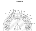
- the figure 1 is a front view of an acyclic reduction device according to the invention.
- flywheel 10 for attachment to one end of the crankshaft of an internal combustion engine.
- This flywheel 10 has a device for reducing the motor acyclisms when idling.
- the device for reducing acyclisms comprises at least one pendular element 20 of mass m having here two recesses 21, 22. Furthermore, two connecting pieces 11, 12 are pivotally mounted respectively about axes 31, 32 which , in the embodiment of the figure 1 , are pins embedded in the steering wheel 10 or additional parts coming together in the body of the steering wheel. The parts 11, 12 can therefore rotate freely about the respective axis 31, 32 so as to accompany the relative translational movement of the pendular element 20 relative to the flywheel 10.
- the connecting pieces 11, 12 are respectively disposed inside the recesses 21, 22, so that, during an acceleration or slowing down of the speed of rotation of the crankshaft, the pendulum element 20 can communicate with the flying 10 a kinetic moment of acyclic compensation. This transfer results from the rotational inertia of the pendular element 20 around the axis of the flywheel 10 and the relative translational movement effected by the pendulum element 20.
- the recesses 21, 22 respectively comprise a zone 220 of contact of circular shape, just as the connecting pieces 11, 12 have a respective profile 110, 120 of also circular shape, conjugated with the circular shape of the contact zones 220.
- connecting pieces 11, 12 and the recesses 21, 22 are made of a self-lubricating material.
- Another advantage of the device of the invention lies in the fact that the functional distances R and L each relate to only one part.
- the geometric dimensioning tolerance is therefore no longer distributed over several pieces, but relates to only one. This results in less stringent tolerance intervals on each piece.
- the distance R is found only on the steering wheel 10, while the distance L is found on the parts 11, 12 of connection.
Landscapes
- Engineering & Computer Science (AREA)
- General Engineering & Computer Science (AREA)
- Physics & Mathematics (AREA)
- Acoustics & Sound (AREA)
- Aviation & Aerospace Engineering (AREA)
- Mechanical Engineering (AREA)
- Connection Of Motors, Electrical Generators, Mechanical Devices, And The Like (AREA)
- Arrangement Or Mounting Of Propulsion Units For Vehicles (AREA)
Abstract
Description
La présente invention concerne un dispositif de réduction d'acyclismes d'un volant d'inertie.The present invention relates to a device for reducing acyclisms of a flywheel.
L'invention s'applique plus particulièrement à la réduction des acyclismes à bas régime des moteurs à combustion interne.The invention applies more particularly to the reduction of low-speed acyclisms of internal combustion engines.
On entend par « acyclismes » les successions de ralentissements et d'accélérations de la vitesse de rotation du vilebrequin des moteurs à combustion interne dont les effets se font sentir surtout aux bas régimes moteur.The term "acyclisms" means the successions of slowdowns and accelerations of the rotational speed of the crankshaft of internal combustion engines whose effects are felt especially at low engine speeds.
La diminution de la vitesse de rotation du vilebrequin lorsque le moteur tourne au ralenti est justifiée par la recherche d'une limitation de la pollution et de la consommation des véhicules en milieu urbain.The reduction in crankshaft rotation speed when the engine is idling is justified by the search for a limitation of pollution and consumption of vehicles in urban areas.
Afin de réduire l'acyclisme au ralenti, une solution couramment utilisée est d'augmenter l'inertie de l'arbre moteur en fixant un volant d'inertie à l'extrémité du vilebrequin.In order to reduce idling acyclism, a commonly used solution is to increase the inertia of the drive shaft by attaching a flywheel to the end of the crankshaft.
Cependant, cette solution connue présente de nombreux inconvénients, à savoir, une augmentation pénalisante de la masse du groupe moto-propulseur, une augmentation nécessaire du démarreur, et une diminution des performances du moteur dont les montées en vitesse deviennent plus lentes.However, this known solution has many drawbacks, namely, a penalizing increase in the mass of the powertrain, a necessary increase of the starter, and a decrease in engine performance whose speed increases become slower.
Pour remédier à ces inconvénients, il a été proposé dans la demande de brevet français n ° 2 781 031 d'associer des éléments pendulaires au volant d'inertie dans le but d'obtenir un dispositif ayant le double avantage, d'une part de réduire les acyclismes, et d'autre part de présenter un moment d'inertie plus faible pour le moteur du fait de la possibilité d'utiliser d'un volant d'inertie de masse plus faible.To overcome these drawbacks, it has been proposed in French Patent Application No. 2,781,031 to associate pendulum elements to the flywheel in order to obtain a device having the double advantage, on the one hand, of reduce acyclisms, and secondly to present a lower moment of inertia for the engine because of the possibility of using a flywheel mass lower.
Le principe d'un tel dispositif de réduction des acyclismes est le suivant. A la périphérie du volant d'inertie sont disposés un ou plusieurs éléments pendulaires qui présentent un degré de liberté dans le sens de la rotation du volant. Lorsque le volant tourne, lesdits éléments pendulaires acquièrent un moment cinétique qui est principalement fonction de la masse m des éléments pendulaires et la distance R de leur point de liaison sur le volant à l'axe de rotation du volant. Si la vitesse de rotation du volant d'inertie diminue à la suite d'un acyclisme, les éléments pendulaires transfèrent au volant, par effet d'inertie, un moment cinétique qui vient s'ajouter à celui du volant et donc compense le ralentissement de la rotation du volant. Au contraire, si la vitesse de rotation du volant d'inertie s'accélère, l'inertie des éléments pendulaires se traduit par un transfert au volant d'un moment cinétique qui se retranche à celui du volant et compense ainsi l'accélération de la rotation du volant. La valeur du moment cinétique positif ou négatif additionnel dépend de la longueur L du pendule équivalent aux éléments pendulaires.The principle of such a device for reducing acyclisms is as follows. At the periphery of the flywheel are arranged one or more pendulum elements which have a degree of freedom in the direction of rotation of the steering wheel. When the steering wheel rotates, said pendular elements acquire a kinetic moment which is mainly a function of the mass m of the pendulum elements and the distance R from their point of connection on the steering wheel to the axis of rotation of the steering wheel. If the speed of rotation of the flywheel decreases following an acyclism, the pendulum elements transfer to the steering wheel, by inertia effect, a kinetic moment that is added to that of the steering wheel and thus compensates for the slowdown of the rotation of the steering wheel. On the contrary, if the speed of rotation of the flywheel accelerates, the inertia of the pendulum elements results in a transfer to the steering wheel of a kinetic moment that retreats to that of the steering wheel and offsets the acceleration of the steering wheel rotation. The value of the additional positive or negative kinetic moment depends on the length L of the pendulum equivalent to the pendulum elements.
Le temps de réponse d'un élément pendulaire à un acyclisme est déterminé par les trois paramètres définis plus haut, à savoir la masse m et les distances R et L. Aussi, ces trois paramètres sont avantageusement choisis de manière à accorder la fréquence propre d'oscillation des éléments pendulaires aux harmoniques majeures des acyclismes, ce qui rend particulièrement efficace l'effet de compensation du dispositif pendulaire de réduction des acyclismes. A titre d'exemple, pour un moteur alternatif à quatre temps et quatre cylindres en ligne, l'harmonique majeure a une fréquence correspondant à deux fois la vitesse de rotation. Un tel moteur équipé d'un dispositif pendulaire accordé par exemple sur l'harmonique H2 permet de combattre la totalité de cet harmonique et peut tourner à ce régime sans irrégularités gênantes et avec un volant d'inertie allégé par rapport à ceux utilisés auparavant. En pratique, il est toutefois préférable d'accorder le pendule sur un harmonique légèrement supérieur au H2 afin d'éviter que le déplacement du pendule ne soit trop important, un débattement toujours inférieur à 30° étant typiquement considéré comme acceptable.The response time of a pendulum element to an acyclism is determined by the three parameters defined above, namely the mass m and the distances R and L. Also, these three parameters are advantageously chosen so as to match the natural frequency of oscillation of the pendulum elements to major harmonics of the acyclisms, which makes particularly effective the compensation effect of the pendulum device for reducing acyclisms. By way of example, for a four-stroke reciprocating engine and four cylinders in line, the major harmonic has a frequency corresponding to twice the speed of rotation. Such an engine equipped with a pendulum device tuned for example on the harmonic H2 can combat all of this harmonic and can turn this regime without annoying irregularities and with a flywheel lightened compared to those used before. In practice, however, it is preferable to tune the pendulum to a harmonic slightly greater than the H2 in order to avoid that the movement of the pendulum is too great, a deflection still less than 30 ° being typically considered acceptable.
La réalisation des éléments pendulaires et leurs moyens de liaison au volant d'inertie peuvent être très variés.The production of the pendulum elements and their means of connection to the flywheel can be very varied.
La demande de brevet français n °
Dans le brevet britannique n°
Toutefois, cette dernière réalisation présente un inconvénient lié à la nature du contact entre les axes de liaison et les alésages. En effet, ce contact est linéique, c'est-à-dire qu'il porte seulement sur une génératrice des surfaces cylindriques constituant l'axe et les alésages. Il n'offre donc que très peu de surface pour reprendre l'effort de centrifugation appliqué à la masse de l'élément pendulaire. Or, ce type d'effort peut devenir très important lorsque la masse, la vitesse de rotation et la distance R deviennent suffisamment grands.However, this last embodiment has a drawback related to the nature of the contact between the connecting pins and the bores. Indeed, this contact is linear, that is to say that it only carries a generatrix cylindrical surfaces constituting the axis and the bores. It therefore offers very little surface to resume the centrifugal force applied to the mass of the pendulum element. However, this type of effort can become very important when the mass, the speed of rotation and the distance R become sufficiently large.
Aussi, un but de la présente invention est de proposer un dispositif de réduction d'acyclismes d'un volant d'inertie, ledit dispositif comprenant au moins un élément pendulaire comportant au moins un évidement, et une pièce de liaison entre ledit volant d'inertie et ledit élément pendulaire, disposée à l'intérieur dudit évidement, qui permettrait de limiter les efforts de centrifugation sur ladite pièce de liaison et sur l'élément pendulaire.Also, an object of the present invention is to provide a device for reducing acyclisms of a flywheel, said device comprising at least one pendular element comprising at least one recess, and a connecting piece between said flywheel. inertia and said pendular element, disposed inside said recess, which would limit the centrifugal forces on said connecting piece and on the pendulum element.
Ce but est atteint, conformément à l'invention, du fait que ladite pièce de liaison présente un profil apte à réaliser un contact surfacique avec ledit évidement.This object is achieved, according to the invention, because said connecting piece has a profile capable of making a surface contact with said recess.
Ainsi, la surface de contact entre l'élément pendulaire et la pièce de liaison étant plus grande, on limite les pressions appliquées par les pièces les unes sur les autres.Thus, the contact surface between the pendular element and the connecting piece being larger, it limits the pressures applied by the parts on each other.
En particulier, l'invention prévoit que, ledit évidement comportant une zone de contact de forme circulaire, ladite pièce de liaison présente un profil de forme circulaire conjuguée de la forme circulaire de ladite zone de contact de l'évidement.In particular, the invention provides that, said recess comprising a circular-shaped contact zone, said connecting piece has a circular shape profile conjugate with the circular shape of said contact zone of the recess.
Avantageusement, ladite pièce de liaison est réalisée dans un matériau auto-lubrifiant. Cette disposition permet de réduire les frottements entre les pièces au niveau de la surface de contact.Advantageously, said connecting piece is made of a self-lubricating material. This arrangement reduces friction between the parts at the contact surface.
L'invention a également pour objet un moteur d'un véhicule automobile dont l'équipage mobile comporte un arbre associé à un volant muni d'un dispositif de réduction des acyclismes tel que défini précédemment.The invention also relates to an engine of a motor vehicle whose mobile assembly comprises a shaft associated with a steering wheel provided with an acyclic reduction device as defined above.
La description qui va suivre en regard du dessin annexé, donné à titre d'exemple non limitatif, fera bien comprendre en quoi consiste l'invention et comment elle peut être réalisée.The following description with reference to the accompanying drawing, given by way of non-limiting example, will make it clear what the invention is and how it can be achieved.
La
Sur la
A cet effet, le dispositif de réduction des acyclismes comprend au moins un élément pendulaire 20 de masse m présentant ici deux évidements 21, 22. Par ailleurs, deux pièces 11, 12 de liaison sont montées pivotantes respectivement autour d'axes 31, 32 qui, dans l'exemple de réalisation de la
Les pièces 11, 12 de liaison sont disposées respectivement à l'intérieur des évidements 21, 22, de sorte que, lors d'une accélération ou d'un ralentissement de la vitesse de rotation du vilebrequin, l'élément pendulaire 20 puisse communiquer au volant 10 un moment cinétique de compensation d'acyclisme. Ce transfert résulte de l'inertie de rotation de l'élément pendulaire 20 autour de l'axe du volant 10 et du mouvement relatif de translation effectué par l'élément pendulaire 20.The connecting
Comme on peut le voir sur la
On obtient ainsi que le contact entre les pièces 11, 12 de liaison et les évidements 21, 22 se répartit sur une surface bien plus grande que dans le cas du contact linéique décrit plus haut en référence à l'état de la technique. Cette surface est suffisante pour reprendre les efforts appliqués sur ces pièces sans que les pressions de contact entre les pièces ne deviennent critiques.Thus, the contact between the connecting
Afin de limiter les frottements entre les pièces 11, 12 de liaison et les évidements 21, 22, il est prévu que lesdites pièces de liaison sont réalisées dans un matériau auto-lubrifiant.In order to limit the friction between the connecting
On remarquera un autre avantage du dispositif de l'invention qui réside dans le fait que les distances fonctionnelles R et L ne portent chacune que sur une seule pièce. La tolérance de dimensionnement géométrique n'est donc plus répartie sur plusieurs pièces, mais porte sur une seule. II en résulte des intervalles de tolérance moins contraignants sur chaque pièce. En l'espèce, la distance R se retrouve uniquement sur le volant 10, tandis que le distance L se retrouve sur les pièces 11, 12 de liaison.Another advantage of the device of the invention lies in the fact that the functional distances R and L each relate to only one part. The geometric dimensioning tolerance is therefore no longer distributed over several pieces, but relates to only one. This results in less stringent tolerance intervals on each piece. In this case, the distance R is found only on the
Claims (6)
Applications Claiming Priority (1)
| Application Number | Priority Date | Filing Date | Title |
|---|---|---|---|
| FR0755623A FR2917145B1 (en) | 2007-06-08 | 2007-06-08 | DEVICE FOR REDUCING ACYCLISTS OF A WHEEL OF INERTIA |
Publications (1)
| Publication Number | Publication Date |
|---|---|
| EP2000701A1 true EP2000701A1 (en) | 2008-12-10 |
Family
ID=38973028
Family Applications (1)
| Application Number | Title | Priority Date | Filing Date |
|---|---|---|---|
| EP08157015A Withdrawn EP2000701A1 (en) | 2007-06-08 | 2008-05-27 | Device for reducing acyclisms in a flywheel |
Country Status (2)
| Country | Link |
|---|---|
| EP (1) | EP2000701A1 (en) |
| FR (1) | FR2917145B1 (en) |
Citations (6)
| Publication number | Priority date | Publication date | Assignee | Title |
|---|---|---|---|---|
| FR773520A (en) * | 1933-05-26 | 1934-11-21 | Device to reduce torsional vibrations | |
| US2306959A (en) * | 1939-10-19 | 1942-12-29 | Continental Aviat & Eng Corp | Crankshaft dynamic balancing means |
| GB598811A (en) | 1945-09-11 | 1948-02-26 | Lemuel John Stone | Improvements in or relating to vibration-damping devices |
| US2484073A (en) * | 1945-05-03 | 1949-10-11 | Wright Aeronautical Corp | Dynamic damper |
| DE4340293A1 (en) * | 1993-11-26 | 1995-06-01 | Freudenberg Carl Fa | Torsional vibration damper |
| FR2781031A1 (en) | 1998-07-09 | 2000-01-14 | Daniel Drecq | Motor vehicle IC engine, has flywheel containing at least one oscillating component to combat cyclic irregularity at low revs |
-
2007
- 2007-06-08 FR FR0755623A patent/FR2917145B1/en not_active Expired - Fee Related
-
2008
- 2008-05-27 EP EP08157015A patent/EP2000701A1/en not_active Withdrawn
Patent Citations (6)
| Publication number | Priority date | Publication date | Assignee | Title |
|---|---|---|---|---|
| FR773520A (en) * | 1933-05-26 | 1934-11-21 | Device to reduce torsional vibrations | |
| US2306959A (en) * | 1939-10-19 | 1942-12-29 | Continental Aviat & Eng Corp | Crankshaft dynamic balancing means |
| US2484073A (en) * | 1945-05-03 | 1949-10-11 | Wright Aeronautical Corp | Dynamic damper |
| GB598811A (en) | 1945-09-11 | 1948-02-26 | Lemuel John Stone | Improvements in or relating to vibration-damping devices |
| DE4340293A1 (en) * | 1993-11-26 | 1995-06-01 | Freudenberg Carl Fa | Torsional vibration damper |
| FR2781031A1 (en) | 1998-07-09 | 2000-01-14 | Daniel Drecq | Motor vehicle IC engine, has flywheel containing at least one oscillating component to combat cyclic irregularity at low revs |
Also Published As
| Publication number | Publication date |
|---|---|
| FR2917145B1 (en) | 2012-08-24 |
| FR2917145A1 (en) | 2008-12-12 |
Similar Documents
| Publication | Publication Date | Title |
|---|---|---|
| EP2383490B1 (en) | Uncoupling pulley | |
| FR2781031A1 (en) | Motor vehicle IC engine, has flywheel containing at least one oscillating component to combat cyclic irregularity at low revs | |
| FR2752895A1 (en) | Torsional vibration damper with transmission elements and guideways | |
| FR2767888A1 (en) | TORSION OSCILLATION SHOCK ABSORBER | |
| EP3558798B1 (en) | Retractable aerodynamic system for vehicles | |
| FR2557655A1 (en) | TORSION DAMPER DEVICE WITH ELASTIC CENTERING MEMBER AND SUPPORT MEMBER INCORPORATED THEREIN, IN PARTICULAR FOR CLUTCHING A MOTOR VEHICLE | |
| WO2014096610A1 (en) | Damping device of pendular oscillator type | |
| EP1181466A1 (en) | Internal combustion engine comprising a means for reducing acyclisms for operation at low engine speeds | |
| FR2736699A1 (en) | TORSION SHOCK ABSORBER | |
| FR3009049A1 (en) | CLUTCH DISC FOR FRICTION CLUTCH | |
| FR2991739A1 (en) | PENDULUM DAMPING DEVICE WITH STABILIZED BEARING ELEMENT | |
| FR2700592A1 (en) | Device for damping vibrations in a motor vehicle. | |
| FR2626625A1 (en) | COAXIAL TYPE STARTER | |
| FR3013414A1 (en) | IMPROVED PULLEY TORSION DAMPING DEVICE | |
| EP2000701A1 (en) | Device for reducing acyclisms in a flywheel | |
| EP0933552B1 (en) | Mechanical device having two modes of operation | |
| FR3014519A1 (en) | TORSION DAMPING DEVICE WITH IMPROVED FILTRATION EFFICIENCY PENDULUM | |
| FR3084714A1 (en) | VARIABLE SPACER FLANGE PULLEY FOR SPEED VARIATOR | |
| FR2803640A1 (en) | Synchronizing assembly for an automotive vehicle transmission includes an arrangement between two synchronizing rings, which has a central part cooperating with a reciprocally shaped part of the synchronizing unit | |
| FR2488328A1 (en) | DEVICE FOR ROTATING A VALVE, IN PARTICULAR FOR INTERNAL COMBUSTION ENGINES | |
| FR2567224A1 (en) | Clutch device for motor vehicles | |
| WO1994008836A1 (en) | High performance power steering | |
| FR2921138A1 (en) | INERTIAL WHEEL WITH TWO MASSES WITH A POSITIONING MEANS. | |
| WO2013174617A1 (en) | Embossment for a pendular system and for a pendulum carrier, and method for producing same | |
| FR3001020A1 (en) | Drive system for rotation of inertial mass coupled to gear shift lever of manual transmission of car, has pinion presenting additional teeth that is arranged for compensating variable thickness of control rod on level of guidance track |
Legal Events
| Date | Code | Title | Description |
|---|---|---|---|
| PUAI | Public reference made under article 153(3) epc to a published international application that has entered the european phase |
Free format text: ORIGINAL CODE: 0009012 |
|
| AK | Designated contracting states |
Kind code of ref document: A1 Designated state(s): AT BE BG CH CY CZ DE DK EE ES FI FR GB GR HR HU IE IS IT LI LT LU LV MC MT NL NO PL PT RO SE SI SK TR |
|
| AX | Request for extension of the european patent |
Extension state: AL BA MK RS |
|
| 17P | Request for examination filed |
Effective date: 20090602 |
|
| 17Q | First examination report despatched |
Effective date: 20090626 |
|
| AKX | Designation fees paid |
Designated state(s): AT BE BG CH CY CZ DE DK EE ES FI FR GB GR HR HU IE IS IT LI LT LU LV MC MT NL NO PL PT RO SE SI SK TR |
|
| STAA | Information on the status of an ep patent application or granted ep patent |
Free format text: STATUS: THE APPLICATION IS DEEMED TO BE WITHDRAWN |
|
| 18D | Application deemed to be withdrawn |
Effective date: 20131203 |