EP2000714A2 - Ensemble de soupapes à liquides - Google Patents
Ensemble de soupapes à liquides Download PDFInfo
- Publication number
- EP2000714A2 EP2000714A2 EP08009591A EP08009591A EP2000714A2 EP 2000714 A2 EP2000714 A2 EP 2000714A2 EP 08009591 A EP08009591 A EP 08009591A EP 08009591 A EP08009591 A EP 08009591A EP 2000714 A2 EP2000714 A2 EP 2000714A2
- Authority
- EP
- European Patent Office
- Prior art keywords
- valve
- valve body
- arrangement according
- valve housing
- housing
- Prior art date
- Legal status (The legal status is an assumption and is not a legal conclusion. Google has not performed a legal analysis and makes no representation as to the accuracy of the status listed.)
- Withdrawn
Links
- 239000012530 fluid Substances 0.000 title claims abstract description 31
- 238000007789 sealing Methods 0.000 claims description 11
- 230000007704 transition Effects 0.000 claims description 4
- 230000002093 peripheral effect Effects 0.000 claims description 3
- 230000008901 benefit Effects 0.000 description 5
- 238000005265 energy consumption Methods 0.000 description 1
- 238000003780 insertion Methods 0.000 description 1
- 230000037431 insertion Effects 0.000 description 1
- 239000007788 liquid Substances 0.000 description 1
- 230000035484 reaction time Effects 0.000 description 1
- 239000004753 textile Substances 0.000 description 1
Images
Classifications
-
- F—MECHANICAL ENGINEERING; LIGHTING; HEATING; WEAPONS; BLASTING
- F16—ENGINEERING ELEMENTS AND UNITS; GENERAL MEASURES FOR PRODUCING AND MAINTAINING EFFECTIVE FUNCTIONING OF MACHINES OR INSTALLATIONS; THERMAL INSULATION IN GENERAL
- F16K—VALVES; TAPS; COCKS; ACTUATING-FLOATS; DEVICES FOR VENTING OR AERATING
- F16K11/00—Multiple-way valves, e.g. mixing valves; Pipe fittings incorporating such valves
- F16K11/02—Multiple-way valves, e.g. mixing valves; Pipe fittings incorporating such valves with all movable sealing faces moving as one unit
- F16K11/04—Multiple-way valves, e.g. mixing valves; Pipe fittings incorporating such valves with all movable sealing faces moving as one unit comprising only lift valves
- F16K11/048—Multiple-way valves, e.g. mixing valves; Pipe fittings incorporating such valves with all movable sealing faces moving as one unit comprising only lift valves with valve seats positioned between movable valve members
Definitions
- the invention relates to a fluid valve assembly having a valve housing having at least one passage for the fluid, and having a valve body movably arranged in the valve body for opening and closing the passage.
- valves for opening and closing a passage for a gas or a liquid are already known in various embodiments.
- the valve body of these valves can be moved between a closed position in which it blocks the passage, and an open position in which it releases the passage back and forth. To open and close the valve thus reversing the direction of the valve body is required. Therefore, these known valves require a relatively high switching time.
- EP 0 233 025 and JP 01229176 A 3/2-way valves are known, each having valve body with two valve plates which close depending on the position of the valve body one of two provided valve seats. By reciprocating the valve body between the closed positions of the valve seats, the passage of the fluid can be switched to other ways. Complete locking of these valves is not possible.
- the DD 48274 describes a similar 3/2-way valve, in which by reciprocating a valve body by means of the fluid two closing positions are reached, in which the valve is completely locked. But only if only one of the two inputs a fluid flows. If fluid flows in from both inputs at the same time, there is always a flow at the outlet.
- the present invention has for its object to provide a valve assembly for fluids that requires only small switching times to open and close.
- valve arrangement according to the invention offers advantages over conventional valves. While the known valves have a minimum opening and closing time required by the required reversal of direction during shifting, which is often longer than would be required for the respective application, unnecessarily much fluid and thus energy is consumed. Due to the significantly shorter switching times in the valve arrangement according to the invention, this disadvantage can be avoided.
- valve housing and the valve body are possible in different ways.
- valve housing are cylindrical at least in the interior and the valve body is piston-shaped. This means that the valve body in the valve housing is moved linearly, which allows particularly high switching speeds.
- valve body has a diameter-reduced central region, which is located in the center positions of the valve body in the region of the fluid passage. In the open position of the valve body, this central region does not hinder the volume flow of the fluid in the passage because of its small diameter.
- the fluid passage in the valve housing may preferably be formed by inlet and outlet openings in the valve housing and the surrounding space of the central region of the valve body. In the middle positions of the valve body, the openings in the valve housing are not closed by the valve body, so that the fluid can flow through the valve housing unhindered.
- the inlet and outlet openings in the direction of movement of the valve body can be arranged offset from one another in the valve housing. As a result, it is sufficient in the closed positions of the valve body to close either only the inlet opening or only the outlet opening in order to block the entire valve.
- the valve body thus has to perform only a small stroke, which can further increase the switching speed. It can be provided in each case only one or more inlet openings and outlet openings.
- the inlet and outlet openings can also be arranged at different peripheral locations, preferably at opposite circumferential locations in the valve housing. In an opposing arrangement of the openings, the fluid flows straight through the valve housing. If the inlet opening and the outlet opening are arranged at a certain angle to one another, the valve housing causes a deflection of the fluid flow when the valve is open.
- sealing points between the valve body and a portion of reduced inner diameter of the valve housing may be arranged to ensure a reliable closing of the valve.
- further sealing points between the valve body and the valve housing can be provided, in particular when the valve body is driven pneumatically or hydraulically.
- valve body is slidably movable with its end portions on the inner surface of the valve housing, i. only slight friction losses occur during the movement of the valve body.
- valve body and valve housing In the area of the sliding surfaces, seals between valve body and valve housing can be provided against leakage.
- valve body can be pneumatically, hydraulically, electromagnetically or electromotively movable.
- valve is advantageous to design as an insert, which can be placed very close to the workstation. As a result, extremely short reaction times can be achieved.
- valve can be made of very simple components.
- valve arrangement according to the invention is extremely wide. In any application in which a large volume flow of a fluid and short switching times are desired for a short time, the valve arrangement can be used to advantage.
- valve arrangement can be used as a compressed air valve in textile machines.
- the use of the valve assembly at several points benefits.
- a blast of compressed air can be released, which accelerates a projectile, which carries the weft thread through the shed.
- relay nozzles which stretch the weft thread beginning by means of compressed air and hold in the desired position. These nozzles are over the entire length of the area of the Weft insertion distributed and cause a crucial part of the energy consumption of an air jet loom.
- the previously used to control the relay nozzles electromagnetically switched valves with a reversal of direction of the valve body between open position and closed position of the valve are open too long for this application and therefore consume unnecessarily much compressed air and thus energy.
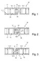
- FIGS. 1 to 3 show an exemplary embodiment of a valve assembly 10 with a cylindrical valve housing 11 and a valve housing 11 disposed in the valve body 12 which in the FIGS. 1 to 3 is shown in different positions.
- the valve body 12 has two end portions 12.1 and 12.2, which have an outer diameter which corresponds to the clear inner diameter of the valve housing 11. With these end portions 12.1 and 12.2, the valve body 12 slide along on the inner surface 11.1. Between the two end regions 12.1 and 12.2, the valve body 12 has a central region 12.3, which is significantly reduced in diameter relative to the end regions 12.1 and 12.2.
- valve body 12 In FIG. 1 the valve body 12 is in a first closed position.
- the valve body 12 forms with the valve housing 11 a first sealing point 13 at the transition from the end region 12.1 to the middle region 12.3, which rests against a section 17 of reduced inside diameter in the valve housing 11.
- This sealing point 13 prevents the flow of a fluid F through the valve housing 11 therethrough.
- valve body 12 has been accelerated in the direction of arrow v, whereby the sealing point 13 has been released.
- the fluid F can now flow through a passage 15 in the valve housing 11, which is formed by an inlet opening 14, the surrounding space 15 of the central region 12.3 of the valve body in the valve housing 11 and an outlet opening 16.
- the inlet opening 14 and the outlet opening 16 are arranged offset on opposite sides of the valve housing 11 and in the direction of movement of the valve body 12, wherein the portion 17 reduced inside diameter of the valve housing 11 between the inlet opening 14 and the outlet opening 16 is located.
- valve body 12 Upon further movement in the direction of arrow v, the valve body 12 reaches its second closed position, such as FIG. 3 shows. Now, the transition between the end portion 12.2 and the central portion 12.3 of the valve body 12 at the portion 17 reduced inside diameter of the valve housing 11 and thus forms a second sealing point 18. The outlet opening 16 is closed by the end portion 12.2, so that no fluid F can flow through the valve housing 11.
- the valve assembly 10 is thus opened by movements of the valve body 12 in a single direction and closed again.
- the switching time of the valve assembly 10 is therefore only about half that of the switching time of conventional valves, where the valve body undergoes a reversal of direction between opening and closing.
Landscapes
- Engineering & Computer Science (AREA)
- General Engineering & Computer Science (AREA)
- Mechanical Engineering (AREA)
- Multiple-Way Valves (AREA)
- Lift Valve (AREA)
- Sliding Valves (AREA)
Applications Claiming Priority (1)
| Application Number | Priority Date | Filing Date | Title |
|---|---|---|---|
| DE102007026698A DE102007026698A1 (de) | 2007-06-08 | 2007-06-08 | Fluid-Ventilanordnung |
Publications (1)
| Publication Number | Publication Date |
|---|---|
| EP2000714A2 true EP2000714A2 (fr) | 2008-12-10 |
Family
ID=39739655
Family Applications (1)
| Application Number | Title | Priority Date | Filing Date |
|---|---|---|---|
| EP08009591A Withdrawn EP2000714A2 (fr) | 2007-06-08 | 2008-05-27 | Ensemble de soupapes à liquides |
Country Status (5)
| Country | Link |
|---|---|
| US (1) | US20080302993A1 (fr) |
| EP (1) | EP2000714A2 (fr) |
| JP (1) | JP2009019765A (fr) |
| CN (1) | CN101382200A (fr) |
| DE (1) | DE102007026698A1 (fr) |
Cited By (1)
| Publication number | Priority date | Publication date | Assignee | Title |
|---|---|---|---|---|
| WO2019219697A1 (fr) * | 2018-05-14 | 2019-11-21 | Ottobock Se & Co. Kgaa | Soupape et prothèse de l'articulation du genou comprenant une telle soupape |
Families Citing this family (3)
| Publication number | Priority date | Publication date | Assignee | Title |
|---|---|---|---|---|
| JP5866804B2 (ja) * | 2011-05-31 | 2016-02-24 | 株式会社豊田自動織機 | エアジェット織機におけるエア供給システム |
| DE102014113655A1 (de) * | 2014-09-22 | 2016-03-24 | Bürkert Werke GmbH | Ventilgehäuse |
| BE1024089B1 (fr) * | 2015-08-03 | 2017-11-13 | Safran Aero Boosters S.A. | Vanne fluidique |
Citations (4)
| Publication number | Priority date | Publication date | Assignee | Title |
|---|---|---|---|---|
| DD48274A (fr) | ||||
| EP0233025A2 (fr) | 1986-01-31 | 1987-08-19 | Fujikura Rubber Ltd. | Soupape à trois voies |
| JPH01229176A (ja) | 1988-03-09 | 1989-09-12 | Toto Ltd | 切換弁 |
| DE60306091T2 (de) | 2003-01-13 | 2006-11-16 | Delphi Technologies, Inc., Troy | Variable Kraftbetätigungsvorrichtungen mit Doppelnadel- Kegelventilanordnung |
Family Cites Families (2)
| Publication number | Priority date | Publication date | Assignee | Title |
|---|---|---|---|---|
| GB1324369A (en) * | 1969-12-18 | 1973-07-25 | Dowty Seals Ltd | Fluid flow control valves and sealing devices therefor |
| US5899232A (en) * | 1998-04-14 | 1999-05-04 | Coulter International Corp. | Debris-resistant hydropneumatic valve |
-
2007
- 2007-06-08 DE DE102007026698A patent/DE102007026698A1/de not_active Withdrawn
-
2008
- 2008-05-27 EP EP08009591A patent/EP2000714A2/fr not_active Withdrawn
- 2008-06-04 US US12/156,704 patent/US20080302993A1/en not_active Abandoned
- 2008-06-06 CN CNA200810210312XA patent/CN101382200A/zh active Pending
- 2008-06-06 JP JP2008148903A patent/JP2009019765A/ja not_active Withdrawn
Patent Citations (4)
| Publication number | Priority date | Publication date | Assignee | Title |
|---|---|---|---|---|
| DD48274A (fr) | ||||
| EP0233025A2 (fr) | 1986-01-31 | 1987-08-19 | Fujikura Rubber Ltd. | Soupape à trois voies |
| JPH01229176A (ja) | 1988-03-09 | 1989-09-12 | Toto Ltd | 切換弁 |
| DE60306091T2 (de) | 2003-01-13 | 2006-11-16 | Delphi Technologies, Inc., Troy | Variable Kraftbetätigungsvorrichtungen mit Doppelnadel- Kegelventilanordnung |
Cited By (4)
| Publication number | Priority date | Publication date | Assignee | Title |
|---|---|---|---|---|
| WO2019219697A1 (fr) * | 2018-05-14 | 2019-11-21 | Ottobock Se & Co. Kgaa | Soupape et prothèse de l'articulation du genou comprenant une telle soupape |
| EP4166116A1 (fr) * | 2018-05-14 | 2023-04-19 | Ottobock SE & Co. KGaA | Soupape et prothèse de l'articulation du genou comprenant une telle soupape |
| US11684495B2 (en) | 2018-05-14 | 2023-06-27 | Ottobock Se & Co. Kgaa | Valve and prosthetic knee joint having such a valve |
| US11801152B2 (en) * | 2018-05-14 | 2023-10-31 | Ottobock Se & Co. Kgaa | Valve and prosthetic knee joint having such a valve |
Also Published As
| Publication number | Publication date |
|---|---|
| JP2009019765A (ja) | 2009-01-29 |
| CN101382200A (zh) | 2009-03-11 |
| DE102007026698A1 (de) | 2008-12-24 |
| US20080302993A1 (en) | 2008-12-11 |
Similar Documents
| Publication | Publication Date | Title |
|---|---|---|
| DE69425760T2 (de) | Fluidventilvorrichtung | |
| EP0279177B1 (fr) | Vanne à volume de fuite | |
| EP0968382B1 (fr) | Soupape a double siege nettoyable | |
| DE2737675A1 (de) | Umschaltventil mit magnetventilsteuerung | |
| DE69718317T2 (de) | Verbesserte Ventilanordnung für Heizsysteme und Wasserheizgeräte | |
| EP3067598B1 (fr) | Vanne multi-voies | |
| DE102007026698A1 (de) | Fluid-Ventilanordnung | |
| DE102013105321A1 (de) | Mehrwegeventil sowie Verfahren zum Betreiben und Verwendung eines solchen Mehrwegeventils | |
| DE29607363U1 (de) | Gasdurchströmtes Ventil | |
| EP4027042A1 (fr) | Soupape directionnelle de véhicule à moteur permettant de régler un écoulement de fluide | |
| EP2113698A2 (fr) | Fil dentaire et emballage le contenant | |
| DE102025108331A1 (de) | Ventilanordnung für ein Mehrwegeventil | |
| DE2013689A1 (de) | Wegeventil | |
| DE29711131U1 (de) | Mehrwegeventil | |
| DE4119402C2 (de) | Schieberventil | |
| DE102005013611B4 (de) | Peumatisches Ventil mit Mitteln zur Betätigung mindestens eines zentralen Ventilsitzes | |
| DE102023101360A1 (de) | Ventil mit Arretierung | |
| DE3337234A1 (de) | Ventileinrichtung mit einem piezoelektrischen oder magnetostriktiven stellglied | |
| WO2019007796A1 (fr) | Soupape | |
| DE69715199T2 (de) | Ventilanordnung für Heizsysteme und Wasserheizgeräte und Verfahren zu ihrer Herstellung | |
| WO2022063733A1 (fr) | Soupape électromagnétique conçue en particulier pour des véhicules automobiles | |
| DE102008014413B4 (de) | Ventil | |
| EP3074679A1 (fr) | Système de soupape à commande magnétique | |
| WO2014008880A2 (fr) | Système de conduites pour le transport de liquides | |
| DE19938699A1 (de) | Feststeller zum Feststellen relativ zueinander beweglicher Objekte |
Legal Events
| Date | Code | Title | Description |
|---|---|---|---|
| PUAI | Public reference made under article 153(3) epc to a published international application that has entered the european phase |
Free format text: ORIGINAL CODE: 0009012 |
|
| AK | Designated contracting states |
Kind code of ref document: A2 Designated state(s): AT BE BG CH CY CZ DE DK EE ES FI FR GB GR HR HU IE IS IT LI LT LU LV MC MT NL NO PL PT RO SE SI SK TR |
|
| AX | Request for extension of the european patent |
Extension state: AL BA MK RS |
|
| STAA | Information on the status of an ep patent application or granted ep patent |
Free format text: STATUS: THE APPLICATION HAS BEEN WITHDRAWN |
|
| 18W | Application withdrawn |
Effective date: 20100629 |