EP2000724B1 - Male and female coupling member, pipe module and method for manufacturing the pipe module - Google Patents
Male and female coupling member, pipe module and method for manufacturing the pipe module Download PDFInfo
- Publication number
- EP2000724B1 EP2000724B1 EP07109803A EP07109803A EP2000724B1 EP 2000724 B1 EP2000724 B1 EP 2000724B1 EP 07109803 A EP07109803 A EP 07109803A EP 07109803 A EP07109803 A EP 07109803A EP 2000724 B1 EP2000724 B1 EP 2000724B1
- Authority
- EP
- European Patent Office
- Prior art keywords
- coupling member
- pipe section
- pipe
- half shell
- male
- Prior art date
- Legal status (The legal status is an assumption and is not a legal conclusion. Google has not performed a legal analysis and makes no representation as to the accuracy of the status listed.)
- Not-in-force
Links
- 230000008878 coupling Effects 0.000 title claims abstract description 161
- 238000010168 coupling process Methods 0.000 title claims abstract description 161
- 238000005859 coupling reaction Methods 0.000 title claims abstract description 161
- 238000004519 manufacturing process Methods 0.000 title claims description 30
- 238000000034 method Methods 0.000 title description 10
- 230000000295 complement effect Effects 0.000 claims abstract description 6
- 238000001125 extrusion Methods 0.000 claims description 9
- 238000003780 insertion Methods 0.000 claims description 4
- 230000037431 insertion Effects 0.000 claims description 4
- 238000001816 cooling Methods 0.000 claims 1
- 238000005516 engineering process Methods 0.000 description 9
- 230000001681 protective effect Effects 0.000 description 7
- 239000000463 material Substances 0.000 description 5
- 238000007789 sealing Methods 0.000 description 4
- 239000004743 Polypropylene Substances 0.000 description 3
- 238000001746 injection moulding Methods 0.000 description 3
- 229920000573 polyethylene Polymers 0.000 description 3
- -1 polypropylene Polymers 0.000 description 3
- 229920001155 polypropylene Polymers 0.000 description 3
- 229920000915 polyvinyl chloride Polymers 0.000 description 3
- 239000004800 polyvinyl chloride Substances 0.000 description 3
- 239000012815 thermoplastic material Substances 0.000 description 3
- XECAHXYUAAWDEL-UHFFFAOYSA-N acrylonitrile butadiene styrene Chemical compound C=CC=C.C=CC#N.C=CC1=CC=CC=C1 XECAHXYUAAWDEL-UHFFFAOYSA-N 0.000 description 2
- 239000004676 acrylonitrile butadiene styrene Substances 0.000 description 2
- 229920000122 acrylonitrile butadiene styrene Polymers 0.000 description 2
- 239000002184 metal Substances 0.000 description 2
- 239000011435 rock Substances 0.000 description 2
- 239000004677 Nylon Substances 0.000 description 1
- 239000004793 Polystyrene Substances 0.000 description 1
- 238000004026 adhesive bonding Methods 0.000 description 1
- 238000005520 cutting process Methods 0.000 description 1
- 230000001419 dependent effect Effects 0.000 description 1
- 238000010586 diagram Methods 0.000 description 1
- 238000006073 displacement reaction Methods 0.000 description 1
- 230000007613 environmental effect Effects 0.000 description 1
- 238000002347 injection Methods 0.000 description 1
- 239000007924 injection Substances 0.000 description 1
- 238000009434 installation Methods 0.000 description 1
- 229920001778 nylon Polymers 0.000 description 1
- 230000003287 optical effect Effects 0.000 description 1
- 239000004033 plastic Substances 0.000 description 1
- 229920003023 plastic Polymers 0.000 description 1
- 229920002223 polystyrene Polymers 0.000 description 1
- 238000002360 preparation method Methods 0.000 description 1
- 238000004080 punching Methods 0.000 description 1
- 239000004576 sand Substances 0.000 description 1
- 239000007787 solid Substances 0.000 description 1
- 238000003466 welding Methods 0.000 description 1
Images


Classifications
-
- F—MECHANICAL ENGINEERING; LIGHTING; HEATING; WEAPONS; BLASTING
- F16—ENGINEERING ELEMENTS AND UNITS; GENERAL MEASURES FOR PRODUCING AND MAINTAINING EFFECTIVE FUNCTIONING OF MACHINES OR INSTALLATIONS; THERMAL INSULATION IN GENERAL
- F16L—PIPES; JOINTS OR FITTINGS FOR PIPES; SUPPORTS FOR PIPES, CABLES OR PROTECTIVE TUBING; MEANS FOR THERMAL INSULATION IN GENERAL
- F16L11/00—Hoses, i.e. flexible pipes
- F16L11/14—Hoses, i.e. flexible pipes made of rigid material, e.g. metal or hard plastics
- F16L11/18—Articulated hoses, e.g. composed of a series of rings
-
- F—MECHANICAL ENGINEERING; LIGHTING; HEATING; WEAPONS; BLASTING
- F16—ENGINEERING ELEMENTS AND UNITS; GENERAL MEASURES FOR PRODUCING AND MAINTAINING EFFECTIVE FUNCTIONING OF MACHINES OR INSTALLATIONS; THERMAL INSULATION IN GENERAL
- F16L—PIPES; JOINTS OR FITTINGS FOR PIPES; SUPPORTS FOR PIPES, CABLES OR PROTECTIVE TUBING; MEANS FOR THERMAL INSULATION IN GENERAL
- F16L27/00—Adjustable joints; Joints allowing movement
- F16L27/02—Universal joints, i.e. with mechanical connection allowing angular movement or adjustment of the axes of the parts in any direction
- F16L27/026—Universal and axially displaceable joints
-
- H—ELECTRICITY
- H02—GENERATION; CONVERSION OR DISTRIBUTION OF ELECTRIC POWER
- H02G—INSTALLATION OF ELECTRIC CABLES OR LINES, OR OF COMBINED OPTICAL AND ELECTRIC CABLES OR LINES
- H02G3/00—Installations of electric cables or lines or protective tubing therefor in or on buildings, equivalent structures or vehicles
- H02G3/02—Details
- H02G3/04—Protective tubing or conduits, e.g. cable ladders or cable troughs
- H02G3/0462—Tubings, i.e. having a closed section
- H02G3/0481—Tubings, i.e. having a closed section with a circular cross-section
-
- H—ELECTRICITY
- H02—GENERATION; CONVERSION OR DISTRIBUTION OF ELECTRIC POWER
- H02G—INSTALLATION OF ELECTRIC CABLES OR LINES, OR OF COMBINED OPTICAL AND ELECTRIC CABLES OR LINES
- H02G9/00—Installations of electric cables or lines in or on the ground or water
- H02G9/06—Installations of electric cables or lines in or on the ground or water in underground tubes or conduits; Tubes or conduits therefor
- H02G9/065—Longitudinally split tubes or conduits therefor
Definitions
- the present invention relates to a divisible pipe module comprising a pipe section, a male coupling member, and a female coupling. It also relates to a method for manufacturing the pipe module.
- Protective ducting is used, for example, for electrical and optical cables laid in the ground, to prevent exposure of the cables to environmental factors, and to provide mechanical protection.
- the pipes that are used to protect the cable can be produced in a variety of materials, and through various production technologies. Extrusion moulded pipe sections are associated with low manufacturing costs and thus offers a cost efficient alternative.
- each pipe section may comprise two pipe section half shells, which can be separated along a longitudinal split-line. As the cable is laid in the trench, the two pipe section half shells are placed around the cable as a sleeve. Also, since the pipe section is longitudinally divisible it can be laid around an already existing cable, and it can be opened up in order to repair a cable or to add an additional cable.
- a series of pipe sections can be laid to form a continuous protective sleeve along the route of the cable.
- the pipe sections have traditionally been laid in a way that they overlap.
- this procedure restricts the angle that can be obtained between adjacent pipe sections, and thus causes a problem when the curvature of the cable route is sharp.
- AU 199527119 discloses a system for protective ducting where the pipe section comprises two half shells, which when mated form a pipe section having a hollow hemispherical section at either end. Through a clamping arrangement, each succeeding pipe section locks the shells of the preceding pipe section together. Through the arrangement, the hemispherical sections provides articulation between adjacent pipe sections like a ball-and-socket joint.
- DE 3606420 discloses a similar apparatus.
- a general object of the present invention is to provide an improved interconnection of pipe sections, in particular an interconnection of pipe sections allowing more flexibility in terms of the routing and curvature of the cable to be protected while maintaining cost efficiency.
- the present invention is based on the understanding that advantages associated with different production technologies could be combined by producing pipe sections and coupling members separately.
- extrusion moulding is not suitable for manufacturing male and female coupling members.
- the coupling members are therefore produced with an alternative production technology such as, for example, injection moulding.
- each pipe section half shell may advantageously have a fixed cross-sectional profile throughout its length, it may be advantageous to utilize extrusion moulding in manufacturing pipe sections, as this helps keeping manufacturing costs down.
- prior art problems such as the limited angle that can be obtained between adjacent pipe sections, can be overcome while a low manufacturing cost can be maintained.
- the pipe modules according to the present invention have the further advantage that they are relatively simple and inexpensive to manufacture and enable a flexible production process.
- the first and second pipe section half shells, and their associated male and female coupling member parts may be placed around the cable to form a sleeve, without having to thread the cable through the pipe module.
- This is advantageous, for example, as the cable is reeled out from a cable winder when laid. It also allows a pipe module to be laid around an already existing cable, and makes it possible to open up a pipe module in order to repair a cable or to add an additional cable.
- the male and female coupling members interconnect adjacent pipe sections, any gap between adjacent pipe sections is prevented, thereby providing a closed protective sleeve along the cable.
- a further advantage with the invention is that, as a larger angle between adjacent pipe modules is enabled, interconnected pipe modules are less sensitive to irregularities, such as rocks, in the trench where they are laid. Thus, excessive digging and preparation of the trench can be avoided. This leads to ease of use and reduced installation cost.
- the first male coupling member part and the second male coupling member part are moveable relative each other in the axial direction.
- the first female coupling member part and the second female coupling member part are moveable relative each other in the axial direction.
- the first male coupling member part is attached at a first end of the first pipe section half shell
- the second male coupling member part is attached at a first end of the second pipe section half shell
- the first female coupling member part is attached at a second end of the first pipe section half shell
- the second female coupling member part is attached at a second end of the second pipe section half shell.
- first and second pipe section half shells, and their associated coupling members can be assembled without a need for precise alignment, thereby facilitating the assembling procedure.
- each of the first and second male coupling member parts may, at the attachment end, be provided with an attachment structure having an axial recess formed therein, the axial recess being adapted to receive a pipe wall of its corresponding pipe section half shell.
- This attachment structure can advantageously be used for attachment to pipe section half shells having a solid pipe wall, and provides a stable attachment of the male coupling member part.
- the attachment structure makes it easy to mount the male coupling member part at the end of the pipe section half shell and can be combined with a variety of attachment means.
- each of the first and second male coupling member parts, at the attachment end may be provided with an attachment structure having at least one insertion element extending in the axial direction, and being adapted to be inserted in a cavity in a pipe wall of its corresponding pipe section half shell.
- This attachment structure can, for example, advantageously be used for attachment to a double walled pipe section comprising first and second double walled pipe section half shells.
- Each double walled pipe section half shell may typically have an inner wall, and an outer wall, held together by bridge elements.
- a plurality of cavities, in the form of hollow channels extending in the axial direction may be formed, wherein each channel is defined by the inner wall, the outer wall, and two adjacent bridge elements.
- the coupling member part can be attached by inserting the at least one insertion element into the at least one hollow channel, thereby providing a stable attachment of the male coupling member part.
- the attachment structure makes it easy to mount the male coupling member part at the end of the pipe section half shell and can be combined with a variety of attachment means.
- attachment structure having an axial recess and at least one axial insertion element provided therein. This may provide further stability to the attachment.
- Each of the first and second male coupling member parts may be attached to its corresponding pipe section half shell by means of stapling.
- Stapling provides an easy and cost efficient way to securely fix a male coupling member part to a pipe section half shell, and allows use of standard tools.
- the attachment structure may be punched to the pipe section half shell with, for example, a pointed hammer whereby, at the point of impact, a portion of the attachment structure penetrates into the surface of the pipe section half shell, thereby fixing the coupling member.
- the radially projecting structure may be an external flange segment.
- the flange segment may extend along the entire perimeter of the male coupling member or over a portion thereof.
- the flange segment may also have the form of, for example, tabs or pins spaced along the perimeter of the male coupling member.
- An extension in the axial direction of the radial recess of the receiving structure may preferably be at least 1.5 times an extension in the axial direction of the radially projecting structure of the male coupling member according to the invention. This allows a play between the male and the female coupling members, making it possible to obtain a larger angle between adjacent pipe sections.
- the extension in the axial direction of the radial recess of the receiving structure can be at least five times the extension in the axial direction of the radially projecting structure, or at least ten times the extension in the axial direction of the radially projecting structure.
- the angle that can be achieved between adjacent pipe sections will depend on the diameter of the pipe section. Generally, a larger diameter requires a larger ratio between the extension in the axial direction of the radial recess of the receiving structure, and the extension in the axial direction of the radially projecting structure, to achieve a given angle between adjacent pipe sections.
- the receiving structure may have an internal flange segment and a shoulder defining the extension in the axial direction of the radial recess of the receiving structure.
- This method of manufacturing has the advantage that it is relatively simple and inexpensive.
- different production technologies can be used. Whereas extrusion moulding, which is associated with low cost, may be used for manufacturing the pipe sections, alternative production technologies, that do not implicate a fixed cross-sectional profile, may be used to manufacture the coupling members.
- the method also provides a flexible production process. For example, to produce a pipe module having a new length is just a matter of cutting the extrusion moulded pipe section in a new length, as the same coupling members can be used. This leads to an increased flexibility and cost efficiency in the production process compared to other techniques, such as injection moulding, where a new tool has to be designed for each new pipe length.
- a pipe module comprising: a pipe section having a first and a second pipe section half shell; a male coupling member having a first and second male coupling member part attached at a first end of the pipe section; a female coupling member having a first and second female coupling member part attached at a second end of the pipe section.
- Each of the male and female coupling member parts has an attachment end adapted to enable attachment thereof to its corresponding pipe section half shell.
- a coupling end of the male coupling member part has a radially projecting structure for enabling connection to a receiving structure of a complementary female coupling member attached to an adjacent pipe module.
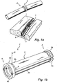
- Figure 1a illustrates two interconnected pipe modules 1 in a trench 5.
- the male and female coupling members 3,4 enables a play whereby an angle can be obtained between adjacent pipe modules 1. This enables a sharper curvature of the route of the pipe modules and makes interconnected pipe modules less sensitive to irregularities, such as rocks, present in the trench.
- the pipe module 1 comprises a pipe section 2 with a male coupling member 3 attached at a first end and a female coupling member 4 attached at a second end.
- the pipe section 2 comprises a first pipe section half shell 2a and a second pipe section half shell 2b.
- the male coupling member 3 comprises a first male coupling member part 3a and a second male coupling member part 3b
- the female coupling member 4 comprises a first female coupling member part 4a and a second female coupling member part 4b.
- the illustrated pipe section 2 comprises two identical pipe section half shells 2a,2b, which are divisible along longitudinal split lines.
- Each pipe section half shell 2a,2b has an essentially semi-circular cross-section, and a longitudinally extending sealing structure 23a,23b,24a,24b.
- the sealing structure 23a,23b,24a,24b is here complementary in such a way that as two pipe section half shells 2a,2b are put together to form a pipe section 2, the sealing structures 23a,23b,24a,24b connect the first half shell 2a and the second half shell 2b.
- the pipe section half shells 2a,2b, including the sealing structure 23a,23b,24a,24b are preferably extrusion moulded in a suitable thermoplastic material, such as polyethene, polypropylene, or PVC.
- a typical pipe section 2 for cable protection has a length of 3000 mm, an internal diameter of approximately 100 mm and the thickness of each half shell 2a,2b can be around 5 mm.
- Examples of other commonly used pipe section diameters(expressed in mm on the form external diameter/internal diameter) are 58/50, 83/75, 160/138.
- the pipe section diameter 160/138 typically is a double walled pipe section, as illustrated in figure 2b .
- each pipe section half shell has an inner wall 26a,26b, and an outer wall 27a, 27b, which are held together by bridge elements 29.
- a plurality of cavities 28, in the form of hollow channels 28 extending in the axial direction, are formed.
- Each channel 28 is defined by the inner wall 26a,26b, the outer wall 27a,27b, and two adjacent bridge elements 29.
- Utilizing a double walled pipe section provides increased ring stiffness, while maintaining low weight.
- double walled pipes may equally well be utilized for other pipe section diameters.
- one of the advantages associated with the present invention is that double walled pipe sections may be utilized also for smaller pipe section diameters.
- FIG. 3 and 4 illustrate the male coupling member 3 comprising the first male coupling member part 3a and the second male coupling member part 3b.
- Each male coupling member part 3a,3b has an essentially semi-circular cross-section and extends in an axial direction thereof, from an attachment end 31a,31b to a coupling end 32a,32b.
- each male coupling member part 3a,3b is provided with an attachment structure 33a,33b.
- Each attachment structure 33a,33b has an axial recess 34a,34b adapted to receive a pipe wall 25a,25b of the pipe section half shell 2a,2b to which the male coupling member part 3a,3b is to be attached.
- each male coupling member part 3a,3b is provided with a radially projecting structure 36a,36b for enabling connection to the complementary female coupling member 4 (as illustrated in figure 2a ).
- the radially projecting structure 36a,36b is here an external flange segment 36a,36b.
- the flange segment 36a,36b is situated at the end of the male coupling member part 3a,3b and extends radially throughout the semi-circular perimeter of the male coupling member part 3a,3b.
- FIG. 5 and 6 illustrate the female coupling member 4, which differs from the male coupling member described above in that each female coupling member part 4a,4b, at the coupling end 42a,42b, is provided with a receiving structure 46a,46b having a radial recess 47a,47b adapted to receive the radially projecting structure 36a,36b of the male coupling member part 3a,3b comprised in the male coupling member 3 (as illustrated in figures 2 to 4 ).
- the receiving structure 46a,46b has an internal flange segment 48a,48b situated at the end of the female coupling part 4a,4b.
- the diameter D1 between the inner tips of the internal flange segments 48a,48b of the assembled female coupling member 4 is smaller than the diameter D2 between the outer tips of the external flange segments 36a,36b of the assembled male coupling member 3.
- the coupling members 3,4 cannot disengage unless the female coupling member 4 is taken apart. This prevents any gap to occur between adjacent pipe sections and, for example, sand or the like to get inside the pipe modules.
- each of the male coupling member parts 3a,3b and the female coupling member parts 4a,4b has a shoulder 39a,39b,49a,49b that restricts to what extent the male coupling member 3 and the female coupling member 4 can overlap.
- the play between the male coupling member 3 and the female coupling members 4 can be altered, and thereby the maximum angle that can be obtained between adjacent pipe sections.
- step 81 pipe sections comprising first and second pipe section half shells 2a,2b, are extrusion moulded in thermoplastic material, such as polyethene, polypropylene, or PVC.
- step 82 the extrusion moulded pipe section is cut in desired length.
- each coupling member part 3a,3b,4a,4b may be stapled to the half shell 2a,2b (as illustrated by the staples 6 in figure 1b ).
- the male and female coupling member parts 3,4 are typically injection moulded in a suitable thermoplastic material, such as polyethene or polypropylene, other manufacturing technologies and materials can be used equally well.
- a suitable thermoplastic material such as polyethene or polypropylene
- ABS acrylonitrile butadiene styrene
- polystyrene polystyrene
- nylon polypropylene
- PVC polystyrene
- Yet another alternative is to produce coupling member parts 3,4 in metal.
- pipe section half shells can equally well be formed by any other suitable manufacturing technology using any other suitable material such as plastics or metal.
- stapling provides an easy and cost efficient way to securely fix coupling member parts 3a,3b,4a,4b to the pipe section half shells 2a,2b
- alternative attachment means for attaching the coupling member parts 3a,3b,4a,4b to the half shells 2a,2b may equally well be used.
- punching may be used as an alternative method.
- Further alternatives could be, for example, riveting, gluing, welding, press-fitting, or snap-fitting.
- the dimension and cross-section of the pipe section half shells 2a,2b, and the coupling member parts may vary.
- first and second pipe section half shells 2a,2b may be longitudinally hinged, rather than being two separate pipe section half shells.
- first and second male coupling member parts 3a,3b may be hinged, as may the first and second female coupling member parts 4a,4b.
Landscapes
- Engineering & Computer Science (AREA)
- General Engineering & Computer Science (AREA)
- Mechanical Engineering (AREA)
- Architecture (AREA)
- Civil Engineering (AREA)
- Structural Engineering (AREA)
- Quick-Acting Or Multi-Walled Pipe Joints (AREA)
- Coupling Device And Connection With Printed Circuit (AREA)
- Rigid Pipes And Flexible Pipes (AREA)
- Resistance Heating (AREA)
Abstract
Description
- The present invention relates to a divisible pipe module comprising a pipe section, a male coupling member, and a female coupling. It also relates to a method for manufacturing the pipe module.
- Protective ducting is used, for example, for electrical and optical cables laid in the ground, to prevent exposure of the cables to environmental factors, and to provide mechanical protection. The pipes that are used to protect the cable can be produced in a variety of materials, and through various production technologies. Extrusion moulded pipe sections are associated with low manufacturing costs and thus offers a cost efficient alternative.
- As a cable is laid in a trench it is typically reeled out from a cable winder. To avoid that the cable has to be thread through the pipe, each pipe section may comprise two pipe section half shells, which can be separated along a longitudinal split-line. As the cable is laid in the trench, the two pipe section half shells are placed around the cable as a sleeve. Also, since the pipe section is longitudinally divisible it can be laid around an already existing cable, and it can be opened up in order to repair a cable or to add an additional cable.
- Now, a series of pipe sections can be laid to form a continuous protective sleeve along the route of the cable. To avoid any gaps between adjacent pipe sections, the pipe sections have traditionally been laid in a way that they overlap. However, this procedure restricts the angle that can be obtained between adjacent pipe sections, and thus causes a problem when the curvature of the cable route is sharp.
- For more demanding environments, such as a submarine environment, alternative protective ducting systems have been developed.
AU 199527119 DE 3606420 discloses a similar apparatus. - A drawback with this latter type of protective ducting system is that it is associated with a considerably higher cost as it requires more costly materials and manufacturing techniques.
- In view of the above-mentioned and other drawbacks of the prior art, a general object of the present invention is to provide an improved interconnection of pipe sections, in particular an interconnection of pipe sections allowing more flexibility in terms of the routing and curvature of the cable to be protected while maintaining cost efficiency.
- The present invention is based on the understanding that advantages associated with different production technologies could be combined by producing pipe sections and coupling members separately. As the cross-sectional profile of the male coupling member, as well as of the female coupling member, varies along the axial direction thereof, extrusion moulding is not suitable for manufacturing male and female coupling members. The coupling members are therefore produced with an alternative production technology such as, for example, injection moulding. At the same time, as each pipe section half shell may advantageously have a fixed cross-sectional profile throughout its length, it may be advantageous to utilize extrusion moulding in manufacturing pipe sections, as this helps keeping manufacturing costs down. By combining production technologies, prior art problems, such as the limited angle that can be obtained between adjacent pipe sections, can be overcome while a low manufacturing cost can be maintained. The pipe modules according to the present invention have the further advantage that they are relatively simple and inexpensive to manufacture and enable a flexible production process.
- As each pipe module can be separated along a longitudinal split-line, the first and second pipe section half shells, and their associated male and female coupling member parts, may be placed around the cable to form a sleeve, without having to thread the cable through the pipe module. This is advantageous, for example, as the cable is reeled out from a cable winder when laid. It also allows a pipe module to be laid around an already existing cable, and makes it possible to open up a pipe module in order to repair a cable or to add an additional cable. As the male and female coupling members interconnect adjacent pipe sections, any gap between adjacent pipe sections is prevented, thereby providing a closed protective sleeve along the cable.
- A further advantage with the invention is that, as a larger angle between adjacent pipe modules is enabled, interconnected pipe modules are less sensitive to irregularities, such as rocks, in the trench where they are laid. Thus, excessive digging and preparation of the trench can be avoided. This leads to ease of use and reduced installation cost.
- The first male coupling member part and the second male coupling member part are moveable relative each other in the axial direction.
- The first female coupling member part and the second female coupling member part are moveable relative each other in the axial direction.
- The first male coupling member part is attached at a first end of the first pipe section half shell, the second male coupling member part is attached at a first end of the second pipe section half shell, the first female coupling member part is attached at a second end of the first pipe section half shell, and the second female coupling member part is attached at a second end of the second pipe section half shell. This arrangement provides a longitudinally divisible pipe module where the first pipe section half shell, along with its male and female coupling member parts, are moveable relative the second pipe section half shell, along with its male and female coupling member parts, in the axial direction.
- Thus, by introducing an axial displacement an increased angle can be obtained between adjacent pipe sections. This also has the further advantage that first and second pipe section half shells, and their associated coupling members, can be assembled without a need for precise alignment, thereby facilitating the assembling procedure.
- According to one embodiment of the invention, each of the first and second male coupling member parts may, at the attachment end, be provided with an attachment structure having an axial recess formed therein, the axial recess being adapted to receive a pipe wall of its corresponding pipe section half shell. This attachment structure can advantageously be used for attachment to pipe section half shells having a solid pipe wall, and provides a stable attachment of the male coupling member part. The attachment structure makes it easy to mount the male coupling member part at the end of the pipe section half shell and can be combined with a variety of attachment means.
- In another embodiment of the invention each of the first and second male coupling member parts, at the attachment end, may be provided with an attachment structure having at least one insertion element extending in the axial direction, and being adapted to be inserted in a cavity in a pipe wall of its corresponding pipe section half shell. This attachment structure can, for example, advantageously be used for attachment to a double walled pipe section comprising first and second double walled pipe section half shells. Each double walled pipe section half shell may typically have an inner wall, and an outer wall, held together by bridge elements. Thereby, a plurality of cavities, in the form of hollow channels extending in the axial direction, may be formed, wherein each channel is defined by the inner wall, the outer wall, and two adjacent bridge elements. The coupling member part can be attached by inserting the at least one insertion element into the at least one hollow channel, thereby providing a stable attachment of the male coupling member part. The attachment structure makes it easy to mount the male coupling member part at the end of the pipe section half shell and can be combined with a variety of attachment means.
- The two embodiments of attachment structure which are described above can also be combined into an attachment structure having an axial recess and at least one axial insertion element provided therein. This may provide further stability to the attachment.
- Each of the first and second male coupling member parts may be attached to its corresponding pipe section half shell by means of stapling. Stapling provides an easy and cost efficient way to securely fix a male coupling member part to a pipe section half shell, and allows use of standard tools. In an alternative embodiment the attachment structure may be punched to the pipe section half shell with, for example, a pointed hammer whereby, at the point of impact, a portion of the attachment structure penetrates into the surface of the pipe section half shell, thereby fixing the coupling member.
- All features described above relating to the attachment structure of the male coupling member are equally applicable to the female coupling member.
- The radially projecting structure may be an external flange segment. The flange segment may extend along the entire perimeter of the male coupling member or over a portion thereof. The flange segment may also have the form of, for example, tabs or pins spaced along the perimeter of the male coupling member. An advantage associated with using a flange segment is that it is easy to manufacture and to adapt in such a way that a considerable play is allowed with respect to a complementary female coupling member in which the flange segment may be received. According to one embodiment the flange segment may be chamfered for increased play.
- An extension in the axial direction of the radial recess of the receiving structure may preferably be at least 1.5 times an extension in the axial direction of the radially projecting structure of the male coupling member according to the invention. This allows a play between the male and the female coupling members, making it possible to obtain a larger angle between adjacent pipe sections. To provide further improved "curve-taking" capabilities the extension in the axial direction of the radial recess of the receiving structure can be at least five times the extension in the axial direction of the radially projecting structure, or at least ten times the extension in the axial direction of the radially projecting structure.
- The angle that can be achieved between adjacent pipe sections will depend on the diameter of the pipe section. Generally, a larger diameter requires a larger ratio between the extension in the axial direction of the radial recess of the receiving structure, and the extension in the axial direction of the radially projecting structure, to achieve a given angle between adjacent pipe sections.
- The receiving structure may have an internal flange segment and a shoulder defining the extension in the axial direction of the radial recess of the receiving structure. By modifying the distance between the internal flange and the shoulder, the play between the male coupling member and the female coupling member can be altered. The shoulder may also restrict to what extent the male coupling member and the female coupling member can overlap.
- According to a third aspect of the invention, the above mentioned and other objects are achieved through a method of manufacturing pipe modules according to the invention comprising the steps of:
- providing a pipe section comprising a first and a second pipe section half shell;
- attaching a first male coupling member part at a first end of the first pipe section half shell; and
- attaching a second male coupling member part at a first end of the second pipe section half shell; and
- attaching a first female coupling member part at a second end of the first pipe section half shell; and
- attaching a second female coupling member part at a second end of the second pipe section half shell.
- This method of manufacturing has the advantage that it is relatively simple and inexpensive. As the coupling member parts are manufactured separately from the pipe section, different production technologies can be used. Whereas extrusion moulding, which is associated with low cost, may be used for manufacturing the pipe sections, alternative production technologies, that do not implicate a fixed cross-sectional profile, may be used to manufacture the coupling members.
- The method also provides a flexible production process. For example, to produce a pipe module having a new length is just a matter of cutting the extrusion moulded pipe section in a new length, as the same coupling members can be used. This leads to an increased flexibility and cost efficiency in the production process compared to other techniques, such as injection moulding, where a new tool has to be designed for each new pipe length.
- Other objectives, features and advantages will appear from the following detailed disclosure, from the attached dependent claims as well as from the drawings.
- In summary the invention relates to, a pipe module comprising: a pipe section having a first and a second pipe section half shell; a male coupling member having a first and second male coupling member part attached at a first end of the pipe section; a female coupling member having a first and second female coupling member part attached at a second end of the pipe section. Each of the male and female coupling member parts has an attachment end adapted to enable attachment thereof to its corresponding pipe section half shell. Further, a coupling end of the male coupling member part has a radially projecting structure for enabling connection to a receiving structure of a complementary female coupling member attached to an adjacent pipe module.
- The above, as well as additional objects, features and advantages of the present invention, will be better understood through the following illustrative and nonlimiting detailed description of preferred embodiments of the present invention, with reference to the appended drawings, where the same reference numerals will be used for similar elements, wherein:
-
Figure 1a is a schematic view of two interconnected pipe modules in a trench. -
Figure 1b is a perspective view of a pipe module according to the present invention. -
Figure 2a illustrates an embodiment of a pipe section comprising first and second pipe section half shells. -
Figure 2b illustrates an embodiment of a pipe section comprising double walled pipe section half shells. -
Figure 3 is a perspective view of a male coupling member comprising first and second male coupling member parts. -
Figure 4 is a cross-section of a male coupling member comprising first and second male coupling member parts. -
Figure 5 is a perspective view of a female coupling member comprising first and second female coupling member parts. -
Figure 6 is a cross-section of a female coupling member comprising first and second female coupling member parts. -
Figure 7 is a cross-section of two interconnected pipe modules. -
Figure 8 is a process diagram illustrating steps associated with the manufacturing of pipe modules. -
Figure 1a illustrates twointerconnected pipe modules 1 in atrench 5. The male andfemale coupling members adjacent pipe modules 1. This enables a sharper curvature of the route of the pipe modules and makes interconnected pipe modules less sensitive to irregularities, such as rocks, present in the trench. - In
figure 1b apipe module 1 that can be used for protective ducting is illustrated. Thepipe module 1 comprises apipe section 2 with amale coupling member 3 attached at a first end and afemale coupling member 4 attached at a second end. Thepipe section 2 comprises a first pipe sectionhalf shell 2a and a second pipe sectionhalf shell 2b. Further, themale coupling member 3 comprises a first malecoupling member part 3a and a second malecoupling member part 3b, and thefemale coupling member 4 comprises a first femalecoupling member part 4a and a second femalecoupling member part 4b. - With reference to
figure 2a , the illustratedpipe section 2 comprises two identical pipesection half shells half shell structure structure section half shells pipe section 2, the sealingstructures first half shell 2a and thesecond half shell 2b. - As each of the pipe section half shells has a fixed cross-sectional profile throughout its length, the pipe
section half shells structure - A
typical pipe section 2 for cable protection has a length of 3000 mm, an internal diameter of approximately 100 mm and the thickness of eachhalf shell figure 2b . Here, each pipe section half shell has aninner wall outer wall bridge elements 29. Thus a plurality ofcavities 28, in the form ofhollow channels 28 extending in the axial direction, are formed. Eachchannel 28 is defined by theinner wall outer wall adjacent bridge elements 29. Utilizing a double walled pipe section provides increased ring stiffness, while maintaining low weight. As understood by a person skilled in the art, double walled pipes may equally well be utilized for other pipe section diameters. Actually, one of the advantages associated with the present invention is that double walled pipe sections may be utilized also for smaller pipe section diameters. -
Figure 3 and 4 illustrate themale coupling member 3 comprising the first malecoupling member part 3a and the second malecoupling member part 3b. Each malecoupling member part attachment end coupling end - At the
attachment end coupling member part attachment structure attachment structure axial recess pipe wall half shell coupling member part - At the
coupling end coupling member part radially projecting structure figure 2a ). Theradially projecting structure external flange segment flange segment coupling member part coupling member part -
Figure 5 and 6 illustrate thefemale coupling member 4, which differs from the male coupling member described above in that each femalecoupling member part coupling end structure radial recess radially projecting structure coupling member part figures 2 to 4 ). The receivingstructure internal flange segment female coupling part - Referring to
figure 4 ,6 , and7 , the diameter D1 between the inner tips of theinternal flange segments female coupling member 4, is smaller than the diameter D2 between the outer tips of theexternal flange segments male coupling member 3. This requires that thefemale coupling member 4 can be opened so that itsradial recesses external flange segments male coupling member 3. Through this arrangement thecoupling members female coupling member 4 is taken apart. This prevents any gap to occur between adjacent pipe sections and, for example, sand or the like to get inside the pipe modules. Further, each of the malecoupling member parts coupling member parts shoulder male coupling member 3 and thefemale coupling member 4 can overlap. By modifying the distance between theinternal flange 48a and theshoulder 49a of the female coupling member part, (and/or theexternal flange 36a and theshoulder 39a of the male coupling member part), the play between themale coupling member 3 and thefemale coupling members 4 can be altered, and thereby the maximum angle that can be obtained between adjacent pipe sections. - With reference to
figure 8 , a preferred method formanufacturing pipe modules 1 is described. Instep 81, pipe sections comprising first and second pipesection half shells step 82, the extrusion moulded pipe section is cut in desired length. - Then, in
step 83, malecoupling member parts coupling member parts coupling member part half shell figure 1b ). - The described embodiments, manufacturing technologies and materials are merely exemplifying. Thus, although the male and female
coupling member parts member parts - Similarly, the pipe section half shells can equally well be formed by any other suitable manufacturing technology using any other suitable material such as plastics or metal.
- Further, whereas stapling provides an easy and cost efficient way to securely fix
coupling member parts section half shells coupling member parts half shells - Further, the dimension and cross-section of the pipe
section half shells - Also, the first and second pipe
section half shells coupling member parts coupling member parts - The invention has mainly been described above with reference to a few embodiments. However, as is readily appreciated by a person skilled in the art, other embodiments than the ones disclosed above are equally possible within the scope of the invention, as defined by the appended claims.
Claims (11)
- A pipe module (1), comprising:a pipe section (2) comprising a first and a second pipe section half shell (2a,2b);a male cooling member (3) produced separately from said pipe section and attached at a first end of said pipe section (2) ; said male coupling member (3) comprising:a first male coupling member part (3a) for attachment to said first pipe section half shell (2a); anda second male coupling member part (3b) for attachment to said second pipe section half shell (2b),each of said male coupling member parts (3a,3b) having an essentially semi-circular cross-section, and extending, in an axial direction thereof, from an attachment end (31a,31b) to a coupling end (32a,32b), wherein each of said male coupling member parts (3a,3b):at said attachment end (31a,31b), is adapted to enable attachment thereof to its corresponding pipe section half shell (2a,2b); andat said coupling end (32a,32b), on a side of said male coupling member part (3a,3b) facing away from a centre of curvature thereof, is provided with a radially projecting structure (36a,36b) for enabling connection to a complementary female coupling member (4) attached to an adjacent pipe section;a female coupling member (4) produced separately from said pipe section and attached at a second end of said pipe section (2); said female coupling member (4) comprising:a first female coupling member part (4a) for attachment to said first pipe section half shell (2a); anda second female coupling member part (4b) for attachment to said second pipe section half shell (2b),each of said female coupling member parts (4a,4b) having an essentially semi-circular cross-section, and extending, in an axial direction thereof, from an attachment end (41a,41b) to a coupling end (42a,42b), wherein each of said female coupling member parts (4a,4b):at said attachment end (41a,41b), is adapted to enable attachment thereof to its corresponding pipe section half shell (2a,2b); andat said coupling end (42a,42b), is provided with a receiving structure (46a,46b) having a radial recess (47a,47b) adapted to receive said radially projecting structure (36a,36b) of the male coupling member part (3a,3b) comprised in the male coupling member (3)characterized in that, when said pipe module is assembled, said first pipe section half shell, along with its male and female coupling member parts, is moveable relative said second pipe section half shell, along with its male and female coupling member parts, in the axial direction.
- A pipe module according to claim 1, wherein said radially projecting structure (36a,36b) is an external flange segment.
- A pipe module according to claim 1 or 2, wherein each of said first and second male coupling member parts (3a,3b) and said first and second female coupling member parts (4a,4b), at said attachment end (31a,31b), is provided with an attachment structure (33a,33b) having an axial recess (34a,34b) formed therein, said recess (34a,34b) being adapted to receive a pipe wall of its corresponding pipe section half shell (2a,2b).
- A pipe module according to any one of the above claims, wherein, each of said first and second male coupling member parts (3a,3b) and said first and second female coupling member parts (4a,4b), at said attachment end (31a,31b), is provided with an attachment structure (33a,33b) having at least one insertion element extending in said axial direction, and being adapted to be inserted in a cavity in a pipe wall of its corresponding pipe section-half shell (2a,2b).
- A pipe module according to any one of the above claims, wherein an extension in the axial direction of said radical recess (47a,47b) of said receiving structure (46a,46b) is at least 1.5 times an extension in axial direction of said radially projecting structure (36a,36b) of the male coupling member (3a, 3b).
- A pipe module according to any one of the above claims, wherein said receiving structure (46a,46b) has an internal flange segment (48a,48b) and a shoulder (49a,49b) defiling the extension in the axial direction of said radial recess (47a, 47b).
- A pipe module according to any one of the above claims, wherein
said first male coupling member part (3a) is attached at a first end of said first pipe section half shell (2a),
said second male coupling member part (3b) is attached at a first end of said second pipe section half shell (2b),
said first female coupling member part (4a) is attached at a second end of said first pipe section half shell (2a), and
said second female coupling member part (4b) is attached at a second end of said second pipe section half shell (2b). - A pipe module according to any one of the above claims, wherein said pipe section (2) is extrusion moulded.
- A pipe module according to any one of the above claims, wherein each of said first and second male coupling member parts (3a,3b) is attached to its corresponding pipe section half shell by means of stapling.
- A method of manufacturing pipe modules (1) according to any one of the above claims, comprising the steps of:providing a pipe section (2) comprising a first and a second pipe section half shell (2a,2b);attaching a first male coupling member part (3a) at a first end of said first pipe section half shell (2a); andattaching a second male coupling member part (3b) at a first end of said second pipe section half shell (2b); andattaching a first female coupling member part (4a) at a second end of said first pipe section half shell (2a); andattaching a second female coupling member part (4b) at a second end of said second pipe section half shell (2b).
- A method of manufacturing pipe modules according to claim 10, wherein:said coupling member parts (3a,3b,4a,4b) are attached through stapling.
Priority Applications (4)
| Application Number | Priority Date | Filing Date | Title |
|---|---|---|---|
| AT07109803T ATE449928T1 (en) | 2007-06-07 | 2007-06-07 | PLUG AND SOCKET ELEMENT, TUBE MODULE AND PRODUCTION PROCESS FOR THE TUBE MODULE |
| DE602007003455T DE602007003455D1 (en) | 2007-06-07 | 2007-06-07 | Plug and socket element, pipe module and manufacturing process for the pipe module |
| EP07109803A EP2000724B1 (en) | 2007-06-07 | 2007-06-07 | Male and female coupling member, pipe module and method for manufacturing the pipe module |
| NO20082651A NO20082651L (en) | 2007-06-07 | 2008-06-09 | Male and female coupling elements, pipeline module and method for manufacturing the pipeline module |
Applications Claiming Priority (1)
| Application Number | Priority Date | Filing Date | Title |
|---|---|---|---|
| EP07109803A EP2000724B1 (en) | 2007-06-07 | 2007-06-07 | Male and female coupling member, pipe module and method for manufacturing the pipe module |
Publications (2)
| Publication Number | Publication Date |
|---|---|
| EP2000724A1 EP2000724A1 (en) | 2008-12-10 |
| EP2000724B1 true EP2000724B1 (en) | 2009-11-25 |
Family
ID=38328231
Family Applications (1)
| Application Number | Title | Priority Date | Filing Date |
|---|---|---|---|
| EP07109803A Not-in-force EP2000724B1 (en) | 2007-06-07 | 2007-06-07 | Male and female coupling member, pipe module and method for manufacturing the pipe module |
Country Status (4)
| Country | Link |
|---|---|
| EP (1) | EP2000724B1 (en) |
| AT (1) | ATE449928T1 (en) |
| DE (1) | DE602007003455D1 (en) |
| NO (1) | NO20082651L (en) |
Families Citing this family (8)
| Publication number | Priority date | Publication date | Assignee | Title |
|---|---|---|---|---|
| DE102013001409B4 (en) * | 2013-01-28 | 2014-12-11 | Gabo Systemtechnik Gmbh | Cable protection tube for receiving cables |
| CN104154345A (en) * | 2014-07-29 | 2014-11-19 | 吴胜利 | Heat-insulating pipe |
| USD913962S1 (en) | 2019-08-13 | 2021-03-23 | Luis Campos | Modular conduit cable management system |
| US11258242B2 (en) | 2019-08-13 | 2022-02-22 | BL United, LLC | Modular conduit cable management assembly |
| USD913961S1 (en) | 2019-08-13 | 2021-03-23 | Luis Campos | Modular conduit cable management assembly |
| USD915302S1 (en) | 2019-08-13 | 2021-04-06 | Luis Campos | Modular conduit cable management assembly |
| USD926707S1 (en) | 2019-08-13 | 2021-08-03 | BL United, LLC | Modular conduit cable management assembly |
| USD1062653S1 (en) | 2022-09-15 | 2025-02-18 | BL United, LLC | Modular conduit cable management assembly |
Family Cites Families (5)
| Publication number | Priority date | Publication date | Assignee | Title |
|---|---|---|---|---|
| US1225867A (en) * | 1915-02-04 | 1917-05-15 | Gerard Schumacher | Sectional culvert-pipe and the like. |
| FR2419393A1 (en) * | 1978-03-10 | 1979-10-05 | Westaflex France | Flexible exhaust pipe for vehicle engine - has sliding end ferrule with sealing cord inside intermediate ferrule |
| DE3606420A1 (en) * | 1986-02-27 | 1987-09-03 | Thyssen Plastik Anger Kg | Tilting joint element |
| DE3702948A1 (en) * | 1987-01-31 | 1988-08-11 | Agintec Ag | PIPE COUPLING |
| DE10261334B4 (en) * | 2002-12-28 | 2010-04-15 | Tracto-Technik Gmbh | sewer pipe |
-
2007
- 2007-06-07 EP EP07109803A patent/EP2000724B1/en not_active Not-in-force
- 2007-06-07 AT AT07109803T patent/ATE449928T1/en not_active IP Right Cessation
- 2007-06-07 DE DE602007003455T patent/DE602007003455D1/en not_active Expired - Fee Related
-
2008
- 2008-06-09 NO NO20082651A patent/NO20082651L/en not_active Application Discontinuation
Also Published As
| Publication number | Publication date |
|---|---|
| DE602007003455D1 (en) | 2010-01-07 |
| NO20082651L (en) | 2008-12-08 |
| ATE449928T1 (en) | 2009-12-15 |
| EP2000724A1 (en) | 2008-12-10 |
Similar Documents
| Publication | Publication Date | Title |
|---|---|---|
| EP2000724B1 (en) | Male and female coupling member, pipe module and method for manufacturing the pipe module | |
| US20220214004A1 (en) | Split segmented bend restrictor | |
| US11402046B2 (en) | Electrical conduit, connection structure for electrical conduit, bell block, method for connecting electrical conduit, method for connecting electrical conduit and bell block, pipe coupling, ring member, double-wall electrical conduit, and connection structure and conduit line for double-wall electrical conduit | |
| US20030151255A1 (en) | Clamshell coupling system and method | |
| US7156126B2 (en) | Pipe insert and pipe assembly formed therewith | |
| CA2639059C (en) | Axially-tensioned pipe joint | |
| EP1586922B1 (en) | Bend restrictor | |
| JP2000283341A (en) | Multiple set pipe device | |
| AU2015207954C1 (en) | Cable breakout assembly | |
| GB2544075A (en) | Improvements relating to bend restrictors | |
| EP4145033A1 (en) | A tubular assembly, components for forming a tubular assembly, and method of forming the components | |
| US20120248392A1 (en) | Fiber Optic Enclosure Assemblies and Methods for Forming and Using the Same | |
| JP2017161070A (en) | Body pipe exchange joint, pipe end sealing tool and construction method of cable protection pipe conduit | |
| KR102366375B1 (en) | Tube coupler for optical cable | |
| JP2008164001A (en) | Protective cover and its manufacturing method | |
| JP2010121744A (en) | Corrugated synthetic resin pipe and its connecting method | |
| CN114197451B (en) | Connect stable steel-pipe pile connection structure | |
| GB2515628A (en) | Armoured cable | |
| JP4681339B2 (en) | Connection structure between communication line and hand hole | |
| EP4098922B1 (en) | Pipe coupling for connection to a plastic cylindrical pipe | |
| KR200356963Y1 (en) | Socket for connecting of double walled pipe | |
| KR100696447B1 (en) | Double wall pipe connection socket and construction method using the same | |
| KR101593231B1 (en) | Prefabricated Steel Pipe Top and bottom steel pipe connection | |
| JP2002078174A (en) | Small duct sleeve | |
| CA2010767C (en) | Reinforced pipe coupling member and method of manufacture |
Legal Events
| Date | Code | Title | Description |
|---|---|---|---|
| PUAI | Public reference made under article 153(3) epc to a published international application that has entered the european phase |
Free format text: ORIGINAL CODE: 0009012 |
|
| 17P | Request for examination filed |
Effective date: 20071218 |
|
| AK | Designated contracting states |
Kind code of ref document: A1 Designated state(s): AT BE BG CH CY CZ DE DK EE ES FI FR GB GR HU IE IS IT LI LT LU LV MC MT NL PL PT RO SE SI SK TR |
|
| AX | Request for extension of the european patent |
Extension state: AL BA HR MK RS |
|
| GRAP | Despatch of communication of intention to grant a patent |
Free format text: ORIGINAL CODE: EPIDOSNIGR1 |
|
| AKX | Designation fees paid |
Designated state(s): AT BE BG CH CY CZ DE DK EE ES FI FR GB GR HU IE IS IT LI LT LU LV MC MT NL PL PT RO SE SI SK TR |
|
| GRAS | Grant fee paid |
Free format text: ORIGINAL CODE: EPIDOSNIGR3 |
|
| GRAA | (expected) grant |
Free format text: ORIGINAL CODE: 0009210 |
|
| AK | Designated contracting states |
Kind code of ref document: B1 Designated state(s): AT BE BG CH CY CZ DE DK EE ES FI FR GB GR HU IE IS IT LI LT LU LV MC MT NL PL PT RO SE SI SK TR |
|
| REG | Reference to a national code |
Ref country code: GB Ref legal event code: FG4D |
|
| REG | Reference to a national code |
Ref country code: CH Ref legal event code: EP |
|
| REG | Reference to a national code |
Ref country code: IE Ref legal event code: FG4D |
|
| REF | Corresponds to: |
Ref document number: 602007003455 Country of ref document: DE Date of ref document: 20100107 Kind code of ref document: P |
|
| REG | Reference to a national code |
Ref country code: SE Ref legal event code: TRGR |
|
| REG | Reference to a national code |
Ref country code: NL Ref legal event code: VDEP Effective date: 20091125 |
|
| LTIE | Lt: invalidation of european patent or patent extension |
Effective date: 20091125 |
|
| PG25 | Lapsed in a contracting state [announced via postgrant information from national office to epo] |
Ref country code: PT Free format text: LAPSE BECAUSE OF FAILURE TO SUBMIT A TRANSLATION OF THE DESCRIPTION OR TO PAY THE FEE WITHIN THE PRESCRIBED TIME-LIMIT Effective date: 20100325 Ref country code: FI Free format text: LAPSE BECAUSE OF FAILURE TO SUBMIT A TRANSLATION OF THE DESCRIPTION OR TO PAY THE FEE WITHIN THE PRESCRIBED TIME-LIMIT Effective date: 20091125 Ref country code: IS Free format text: LAPSE BECAUSE OF FAILURE TO SUBMIT A TRANSLATION OF THE DESCRIPTION OR TO PAY THE FEE WITHIN THE PRESCRIBED TIME-LIMIT Effective date: 20100325 Ref country code: LT Free format text: LAPSE BECAUSE OF FAILURE TO SUBMIT A TRANSLATION OF THE DESCRIPTION OR TO PAY THE FEE WITHIN THE PRESCRIBED TIME-LIMIT Effective date: 20091125 |
|
| PG25 | Lapsed in a contracting state [announced via postgrant information from national office to epo] |
Ref country code: LV Free format text: LAPSE BECAUSE OF FAILURE TO SUBMIT A TRANSLATION OF THE DESCRIPTION OR TO PAY THE FEE WITHIN THE PRESCRIBED TIME-LIMIT Effective date: 20091125 Ref country code: SI Free format text: LAPSE BECAUSE OF FAILURE TO SUBMIT A TRANSLATION OF THE DESCRIPTION OR TO PAY THE FEE WITHIN THE PRESCRIBED TIME-LIMIT Effective date: 20091125 Ref country code: PL Free format text: LAPSE BECAUSE OF FAILURE TO SUBMIT A TRANSLATION OF THE DESCRIPTION OR TO PAY THE FEE WITHIN THE PRESCRIBED TIME-LIMIT Effective date: 20091125 Ref country code: CY Free format text: LAPSE BECAUSE OF FAILURE TO SUBMIT A TRANSLATION OF THE DESCRIPTION OR TO PAY THE FEE WITHIN THE PRESCRIBED TIME-LIMIT Effective date: 20091125 |
|
| PG25 | Lapsed in a contracting state [announced via postgrant information from national office to epo] |
Ref country code: BE Free format text: LAPSE BECAUSE OF FAILURE TO SUBMIT A TRANSLATION OF THE DESCRIPTION OR TO PAY THE FEE WITHIN THE PRESCRIBED TIME-LIMIT Effective date: 20091125 Ref country code: AT Free format text: LAPSE BECAUSE OF FAILURE TO SUBMIT A TRANSLATION OF THE DESCRIPTION OR TO PAY THE FEE WITHIN THE PRESCRIBED TIME-LIMIT Effective date: 20091125 |
|
| PG25 | Lapsed in a contracting state [announced via postgrant information from national office to epo] |
Ref country code: DK Free format text: LAPSE BECAUSE OF FAILURE TO SUBMIT A TRANSLATION OF THE DESCRIPTION OR TO PAY THE FEE WITHIN THE PRESCRIBED TIME-LIMIT Effective date: 20091125 Ref country code: EE Free format text: LAPSE BECAUSE OF FAILURE TO SUBMIT A TRANSLATION OF THE DESCRIPTION OR TO PAY THE FEE WITHIN THE PRESCRIBED TIME-LIMIT Effective date: 20091125 Ref country code: NL Free format text: LAPSE BECAUSE OF FAILURE TO SUBMIT A TRANSLATION OF THE DESCRIPTION OR TO PAY THE FEE WITHIN THE PRESCRIBED TIME-LIMIT Effective date: 20091125 Ref country code: ES Free format text: LAPSE BECAUSE OF FAILURE TO SUBMIT A TRANSLATION OF THE DESCRIPTION OR TO PAY THE FEE WITHIN THE PRESCRIBED TIME-LIMIT Effective date: 20100308 Ref country code: BG Free format text: LAPSE BECAUSE OF FAILURE TO SUBMIT A TRANSLATION OF THE DESCRIPTION OR TO PAY THE FEE WITHIN THE PRESCRIBED TIME-LIMIT Effective date: 20100225 Ref country code: RO Free format text: LAPSE BECAUSE OF FAILURE TO SUBMIT A TRANSLATION OF THE DESCRIPTION OR TO PAY THE FEE WITHIN THE PRESCRIBED TIME-LIMIT Effective date: 20091125 |
|
| PG25 | Lapsed in a contracting state [announced via postgrant information from national office to epo] |
Ref country code: SK Free format text: LAPSE BECAUSE OF FAILURE TO SUBMIT A TRANSLATION OF THE DESCRIPTION OR TO PAY THE FEE WITHIN THE PRESCRIBED TIME-LIMIT Effective date: 20091125 Ref country code: CZ Free format text: LAPSE BECAUSE OF FAILURE TO SUBMIT A TRANSLATION OF THE DESCRIPTION OR TO PAY THE FEE WITHIN THE PRESCRIBED TIME-LIMIT Effective date: 20091125 |
|
| PLBE | No opposition filed within time limit |
Free format text: ORIGINAL CODE: 0009261 |
|
| STAA | Information on the status of an ep patent application or granted ep patent |
Free format text: STATUS: NO OPPOSITION FILED WITHIN TIME LIMIT |
|
| PG25 | Lapsed in a contracting state [announced via postgrant information from national office to epo] |
Ref country code: GR Free format text: LAPSE BECAUSE OF FAILURE TO SUBMIT A TRANSLATION OF THE DESCRIPTION OR TO PAY THE FEE WITHIN THE PRESCRIBED TIME-LIMIT Effective date: 20100226 |
|
| 26N | No opposition filed |
Effective date: 20100826 |
|
| PG25 | Lapsed in a contracting state [announced via postgrant information from national office to epo] |
Ref country code: MC Free format text: LAPSE BECAUSE OF NON-PAYMENT OF DUE FEES Effective date: 20100630 |
|
| REG | Reference to a national code |
Ref country code: FR Ref legal event code: ST Effective date: 20110228 |
|
| PG25 | Lapsed in a contracting state [announced via postgrant information from national office to epo] |
Ref country code: IT Free format text: LAPSE BECAUSE OF FAILURE TO SUBMIT A TRANSLATION OF THE DESCRIPTION OR TO PAY THE FEE WITHIN THE PRESCRIBED TIME-LIMIT Effective date: 20091125 |
|
| PG25 | Lapsed in a contracting state [announced via postgrant information from national office to epo] |
Ref country code: MT Free format text: LAPSE BECAUSE OF FAILURE TO SUBMIT A TRANSLATION OF THE DESCRIPTION OR TO PAY THE FEE WITHIN THE PRESCRIBED TIME-LIMIT Effective date: 20091125 Ref country code: IE Free format text: LAPSE BECAUSE OF NON-PAYMENT OF DUE FEES Effective date: 20100607 Ref country code: DE Free format text: LAPSE BECAUSE OF NON-PAYMENT OF DUE FEES Effective date: 20110101 |
|
| PG25 | Lapsed in a contracting state [announced via postgrant information from national office to epo] |
Ref country code: FR Free format text: LAPSE BECAUSE OF NON-PAYMENT OF DUE FEES Effective date: 20100630 |
|
| PGFP | Annual fee paid to national office [announced via postgrant information from national office to epo] |
Ref country code: SE Payment date: 20110616 Year of fee payment: 5 |
|
| REG | Reference to a national code |
Ref country code: CH Ref legal event code: PL |
|
| GBPC | Gb: european patent ceased through non-payment of renewal fee |
Effective date: 20110607 |
|
| PG25 | Lapsed in a contracting state [announced via postgrant information from national office to epo] |
Ref country code: LI Free format text: LAPSE BECAUSE OF NON-PAYMENT OF DUE FEES Effective date: 20110630 Ref country code: CH Free format text: LAPSE BECAUSE OF NON-PAYMENT OF DUE FEES Effective date: 20110630 |
|
| PG25 | Lapsed in a contracting state [announced via postgrant information from national office to epo] |
Ref country code: GB Free format text: LAPSE BECAUSE OF NON-PAYMENT OF DUE FEES Effective date: 20110607 |
|
| PG25 | Lapsed in a contracting state [announced via postgrant information from national office to epo] |
Ref country code: LU Free format text: LAPSE BECAUSE OF NON-PAYMENT OF DUE FEES Effective date: 20100607 Ref country code: HU Free format text: LAPSE BECAUSE OF FAILURE TO SUBMIT A TRANSLATION OF THE DESCRIPTION OR TO PAY THE FEE WITHIN THE PRESCRIBED TIME-LIMIT Effective date: 20100526 |
|
| PG25 | Lapsed in a contracting state [announced via postgrant information from national office to epo] |
Ref country code: TR Free format text: LAPSE BECAUSE OF FAILURE TO SUBMIT A TRANSLATION OF THE DESCRIPTION OR TO PAY THE FEE WITHIN THE PRESCRIBED TIME-LIMIT Effective date: 20091125 |
|
| REG | Reference to a national code |
Ref country code: SE Ref legal event code: EUG |
|
| PG25 | Lapsed in a contracting state [announced via postgrant information from national office to epo] |
Ref country code: SE Free format text: LAPSE BECAUSE OF NON-PAYMENT OF DUE FEES Effective date: 20120608 |