EP2000743B1 - Temperaturausgleichsverfahren und -installation mit einem Wasserversorgungssystem - Google Patents
Temperaturausgleichsverfahren und -installation mit einem Wasserversorgungssystem Download PDFInfo
- Publication number
- EP2000743B1 EP2000743B1 EP07252249.3A EP07252249A EP2000743B1 EP 2000743 B1 EP2000743 B1 EP 2000743B1 EP 07252249 A EP07252249 A EP 07252249A EP 2000743 B1 EP2000743 B1 EP 2000743B1
- Authority
- EP
- European Patent Office
- Prior art keywords
- fluid
- closed
- chamber structure
- cladding chamber
- piping
- Prior art date
- Legal status (The legal status is an assumption and is not a legal conclusion. Google has not performed a legal analysis and makes no representation as to the accuracy of the status listed.)
- Not-in-force
Links
Images


Classifications
-
- E—FIXED CONSTRUCTIONS
- E03—WATER SUPPLY; SEWERAGE
- E03B—INSTALLATIONS OR METHODS FOR OBTAINING, COLLECTING, OR DISTRIBUTING WATER
- E03B11/00—Arrangements or adaptations of tanks for water supply
- E03B11/10—Arrangements or adaptations of tanks for water supply for public or like main water supply
- E03B11/14—Arrangements or adaptations of tanks for water supply for public or like main water supply of underground tanks
-
- F—MECHANICAL ENGINEERING; LIGHTING; HEATING; WEAPONS; BLASTING
- F24—HEATING; RANGES; VENTILATING
- F24D—DOMESTIC- OR SPACE-HEATING SYSTEMS, e.g. CENTRAL HEATING SYSTEMS; DOMESTIC HOT-WATER SUPPLY SYSTEMS; ELEMENTS OR COMPONENTS THEREFOR
- F24D11/00—Central heating systems using heat accumulated in storage masses
-
- E—FIXED CONSTRUCTIONS
- E03—WATER SUPPLY; SEWERAGE
- E03B—INSTALLATIONS OR METHODS FOR OBTAINING, COLLECTING, OR DISTRIBUTING WATER
- E03B11/00—Arrangements or adaptations of tanks for water supply
-
- F—MECHANICAL ENGINEERING; LIGHTING; HEATING; WEAPONS; BLASTING
- F24—HEATING; RANGES; VENTILATING
- F24F—AIR-CONDITIONING; AIR-HUMIDIFICATION; VENTILATION; USE OF AIR CURRENTS FOR SCREENING
- F24F5/00—Air-conditioning systems or apparatus not covered by F24F1/00 or F24F3/00, e.g. using solar heat or combined with household units such as an oven or water heater
- F24F5/0046—Air-conditioning systems or apparatus not covered by F24F1/00 or F24F3/00, e.g. using solar heat or combined with household units such as an oven or water heater using natural energy, e.g. solar energy, energy from the ground
-
- F—MECHANICAL ENGINEERING; LIGHTING; HEATING; WEAPONS; BLASTING
- F24—HEATING; RANGES; VENTILATING
- F24T—GEOTHERMAL COLLECTORS; GEOTHERMAL SYSTEMS
- F24T10/00—Geothermal collectors
- F24T10/10—Geothermal collectors with circulation of working fluids through underground channels, the working fluids not coming into direct contact with the ground
-
- F—MECHANICAL ENGINEERING; LIGHTING; HEATING; WEAPONS; BLASTING
- F28—HEAT EXCHANGE IN GENERAL
- F28D—HEAT-EXCHANGE APPARATUS, NOT PROVIDED FOR IN ANOTHER SUBCLASS, IN WHICH THE HEAT-EXCHANGE MEDIA DO NOT COME INTO DIRECT CONTACT
- F28D1/00—Heat-exchange apparatus having stationary conduit assemblies for one heat-exchange medium only, the media being in contact with different sides of the conduit wall, in which the other heat-exchange medium is a large body of fluid, e.g. domestic or motor car radiators
- F28D1/02—Heat-exchange apparatus having stationary conduit assemblies for one heat-exchange medium only, the media being in contact with different sides of the conduit wall, in which the other heat-exchange medium is a large body of fluid, e.g. domestic or motor car radiators with heat-exchange conduits immersed in the body of fluid
-
- F—MECHANICAL ENGINEERING; LIGHTING; HEATING; WEAPONS; BLASTING
- F28—HEAT EXCHANGE IN GENERAL
- F28D—HEAT-EXCHANGE APPARATUS, NOT PROVIDED FOR IN ANOTHER SUBCLASS, IN WHICH THE HEAT-EXCHANGE MEDIA DO NOT COME INTO DIRECT CONTACT
- F28D15/00—Heat-exchange apparatus with the intermediate heat-transfer medium in closed tubes passing into or through the conduit walls ; Heat-exchange apparatus employing intermediate heat-transfer medium or bodies
-
- F—MECHANICAL ENGINEERING; LIGHTING; HEATING; WEAPONS; BLASTING
- F24—HEATING; RANGES; VENTILATING
- F24F—AIR-CONDITIONING; AIR-HUMIDIFICATION; VENTILATION; USE OF AIR CURRENTS FOR SCREENING
- F24F5/00—Air-conditioning systems or apparatus not covered by F24F1/00 or F24F3/00, e.g. using solar heat or combined with household units such as an oven or water heater
- F24F5/0046—Air-conditioning systems or apparatus not covered by F24F1/00 or F24F3/00, e.g. using solar heat or combined with household units such as an oven or water heater using natural energy, e.g. solar energy, energy from the ground
- F24F2005/0057—Air-conditioning systems or apparatus not covered by F24F1/00 or F24F3/00, e.g. using solar heat or combined with household units such as an oven or water heater using natural energy, e.g. solar energy, energy from the ground receiving heat-exchange fluid from a closed circuit in the ground
-
- Y—GENERAL TAGGING OF NEW TECHNOLOGICAL DEVELOPMENTS; GENERAL TAGGING OF CROSS-SECTIONAL TECHNOLOGIES SPANNING OVER SEVERAL SECTIONS OF THE IPC; TECHNICAL SUBJECTS COVERED BY FORMER USPC CROSS-REFERENCE ART COLLECTIONS [XRACs] AND DIGESTS
- Y02—TECHNOLOGIES OR APPLICATIONS FOR MITIGATION OR ADAPTATION AGAINST CLIMATE CHANGE
- Y02B—CLIMATE CHANGE MITIGATION TECHNOLOGIES RELATED TO BUILDINGS, e.g. HOUSING, HOUSE APPLIANCES OR RELATED END-USER APPLICATIONS
- Y02B10/00—Integration of renewable energy sources in buildings
- Y02B10/40—Geothermal heat-pumps
-
- Y—GENERAL TAGGING OF NEW TECHNOLOGICAL DEVELOPMENTS; GENERAL TAGGING OF CROSS-SECTIONAL TECHNOLOGIES SPANNING OVER SEVERAL SECTIONS OF THE IPC; TECHNICAL SUBJECTS COVERED BY FORMER USPC CROSS-REFERENCE ART COLLECTIONS [XRACs] AND DIGESTS
- Y02—TECHNOLOGIES OR APPLICATIONS FOR MITIGATION OR ADAPTATION AGAINST CLIMATE CHANGE
- Y02E—REDUCTION OF GREENHOUSE GAS [GHG] EMISSIONS, RELATED TO ENERGY GENERATION, TRANSMISSION OR DISTRIBUTION
- Y02E10/00—Energy generation through renewable energy sources
- Y02E10/10—Geothermal energy
Definitions
- the present invention is related to a methodology and installation for temperature equilibrating conduction, and more particularly, to the use of specific piping from a water supply system and the water running in the pipe as a carrier to conduct the thermal energy in the stratum to a subject matter on the ground.
- DE 2834442 discloses a method of heating a building using heat extracted from a central water supply, the pipe of which includes an underground portion.
- the primary purpose of the present invention is to provide a methodology and installation to execute temperature equilibration thermal transmission between the thermal energy in the deeper stratum and a subject matter on the ground designated for transmission of thermal energy by a closed piping comprised of underground water pipe buried in the underground for a water supply system and piping disposed on the ground to transmit the thermal energy in the stratum conducted by the underground pipe through the current running in the piping. More particularly, the invention provides a thermal energy transmission system as set out below in claim 1. Preferred features of the invention include those contained in the accompanying dependent claims.
- methodology and installation for temperature equilibration by means of a water supply system operates on having an underground water pipe of the conventional water supply system buried in the stratum and water running in the pipe as carriers to be incorporated with a flow passage comprised of a pipe constructed on the ground, a temperature equilibrating object, and a pump.
- the current pumped by the pump, or the circulating current resulted from the convection effect due to temperature difference when the hotter water runs to the cooler water and vice versa, or the current resulted from shunting effect functions in systems described hereinafter as a carrier of thermal energy to execute thermal transmission of temperature equilibration between the thermal energy in the stratum and a subject matter on ground to receive the thermal energy transmission, thus to replace or support the conventional air conditioning system that consumes massive energy and further to save energy.
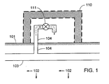
- FIG. 1 for a layout of a conventional water supply piping and a piping of a building, wherein,
- a preferred thermal energy transmission system has a cladding chamber structure for temperature equilibration provided to the ground or underground water supply piping of a water supply system.
- the thermal energy carried by the water current in the water supply piping flows to another gaseous or liquid state fluid of the subject matter into an open space, building, or other closed or semi-closed structure of the subject matter for temperature equilibration to perform the indirect transmission of thermal energy for the purpose of temperature equilibration.
- Fig. 2 shows a schematic view of a preferred embodiment of the present invention, wherein a system of a cladding chamber structure for temperature equilibration is provided to perform open fluid circulation to an open space.
- the system includes a cladding chamber structure 220 for temperature equilibration disposed at where surrounds a certain section of the underground water pipe 103 of the water supply system buried in a deep stratum 102; both end surfaces are closed to the cladding chamber structure 220 for temperature equilibration.
- One or a plurality of fluid inlet 218 and a fluid piping 221 leading to an open space above the surface 101 of the earth are disposed at one end in the vicinity of the closed end surface; one or a plurality of fluid outlet 219 and a fluid piping 231 leading to the open space are disposed on the other end of the cladding chamber structure 220 to allow the gaseous or liquid state fluid flowing in and out.
- the fluid may perform convection circulation by the effects that the cooler descends and the hotter ascends, or driven by a motor with the installation of a liquid pump 123, or driven by other mechanical kinetics or by manual so to pump the fluid passing through the cladding chamber structure 220 into the fluid piping 221 to the open space.
- the fluid in the open space flows through the fluid piping 231 back to the cladding chamber structure 220 so to perform the temperature equilibration transmission of indirect conduction of thermal energy between the water supply system and the open space.
- the fluid piping 221 and another fluid piping 231 are respectively leading to the open space to perform the open fluid circulation; and the optional filtration device 124 may be each disposed to the fluid inlet and outlet of the fluid piping 221 and another fluid piping 231.
- Fig. 3 shows a schematic view of another preferred embodiment yet of the present invention, wherein the system includes the cladding chamber structure for temperature equilibration to perform open fluid circulation to an interior space in a building or other closed or semi-closed structure.
- the system includes a cladding chamber structure 220 for temperature equilibration disposed at where surrounds a certain section of the underground water pipe 103 of the water supply system; both end surfaces are closed to the cladding chamber structure 220 for temperature equilibration.
- One or a plurality of fluid inlet 218 and the fluid piping 221 leading to the space inside the closed or semi-closed structure in the building 110 are disposed at one end in the vicinity of the closed end surface; one or a plurality of fluid outlet 219 and a fluid piping 231 leading to the space inside the closed or semi-closed structure in the building 110 are disposed on the other end of the cladding chamber structure 220 to allow the gaseous or liquid state fluid flowing in and out.
- the fluid may perform convection circulation by the effects that the cooler descends and the hotter ascends, or driven by a motor with the installation of a liquid pump 123, or driven by other mechanical kinetics or by manual so to pump the fluid passing through the cladding chamber structure 220 into the fluid piping 221 to the space inside the building 110 or other closed or semi-closed structure.
- the fluid then flows through the fluid piping 231 back to the cladding chamber structure 220 so to perform the temperature equilibration transmission of indirect conduction of thermal energy between the water supply system and the space inside the building 110 or other closed or semi-closed structure.
- the fluid piping 221 and another fluid piping 231 are respectively leading to the interior space in the building 110 or other closed or semi-closed structure to perform the open fluid circulation; and the optional filtration device 124 may be each disposed to the fluid inlet and outlet of the fluid piping 221 and another fluid piping 231.
- Fig. 4 shows a schematic view of another preferred embodiment yet of the present invention, wherein the system includes the cladding chamber structure for temperature equilibration to perform closed fluid circulation to an open space.
- the system includes a cladding chamber structure 220 for temperature equilibration disposed at where surrounds a certain section of the underground water pipe 103 of the water supply system; both end surfaces are closed to the cladding chamber structure 220 for temperature equilibration.
- One or a plurality of fluid inlet 218 and the fluid piping 221 leading to the open space are disposed at one end in the vicinity of the closed end surface; one or a plurality of fluid outlet 219 and a fluid piping 231 leading to the open space are disposed on the other end of the cladding chamber structure 220 to allow the gaseous or liquid state fluid flowing in and out.
- the fluid may perform convection circulation by the effects that the cooler descends and the hotter ascends, or driven by a motor with the installation of a liquid pump 123, or driven by other mechanical kinetics or by manual so to pump the fluid passing through the cladding chamber structure 220 into the fluid piping 221 to the temperature equilibrating installation 122 disposed in the open space.
- the fluid then flows through the fluid piping 231 back to the cladding chamber structure 220 so to perform the temperature equilibration transmission of indirect conduction of thermal energy between the water supply system and the open space through temperature equilibrating installation 122.
- the fluid piping 221 and another fluid piping 231 are respectively leading to the temperature equilibrating installation 122 disposed in the open space to perform the closed fluid circulation for transmission of temperature equilibration.
- Fig. 5 shows a schematic view of another preferred embodiment yet of the present invention, wherein the system includes the cladding chamber structure for temperature equilibration to perform closed fluid circulation to an interior space in a building or other closed or semi-closed structure.
- the system includes a cladding chamber structure 220 for temperature equilibration disposed at where surrounds a certain section of the underground water pipe 103 of the water supply system; both end surfaces are closed to the cladding chamber structure 220 for temperature equilibration.
- One or a plurality of fluid inlet 218 and the fluid piping 221 leading to the interior space in a building 110 or a closed or semi-closed structure are disposed at one end in the vicinity of the closed end surface; one or a plurality of fluid outlet 219 and a fluid piping 231 leading to the interior space in a building 110 or a closed or semi-closed structure are disposed on the other end of the cladding chamber structure 220 to allow the gaseous or liquid state fluid flowing in and out.
- the fluid may perform convection circulation by the effects that the cooler descends and the hotter ascends, or driven by a motor with the installation of a liquid pump 123, or driven by other mechanical kinetics or by manual so to pump the fluid passing through the cladding chamber structure 220 into the fluid piping 221 to the temperature equilibrating installation 122 disposed in the interior space in the building 110 or other closed or semi-closed structure.
- the fluid then flows through the fluid piping 231 back to the cladding chamber structure 220 so to perform the temperature equilibration transmission of indirect conduction of thermal energy between the water supply system and the interior space in the building 110 or other closed or semi-closed structure through the temperature equilibrating installation 122.
- the fluid piping 221 and another fluid piping 231 are respectively leading to the temperature equilibrating installation 122 disposed in the interior space in the building 110 or other closed or semi-closed structure to perform the closed fluid circulation for transmission of temperature equilibration.
- the subject matter for the temperature equilibration operation performed by the methodology and installation of temperature equilibration with a water supply system of the present invention includes:
- the building referred in these preferred embodiments described above for the methodology and installation of temperature equilibration with a water supply system of the present invention includes house, warehouse, or any building in column or any other geometric form, or any other designated building comprised of a semi-closed or closed structure designed as desired. Other functioning for the general house to live in, the interior space may be further operated to accommodate:
- the natural thermal energy from the water supply system either cools or maintains the installations and facilities in a certain range of temperature.
- the methodology and installation of temperature equilibration with a water supply system of the present invention by operating on the natural thermal energy (ranging between 12 ⁇ 16 °C) in the stratum absorbed by the underground water pipe of an existing water supply system to have current as a carrier to flow through a pipe disposed at where closer to the surface of the earth, exposed from the ground or in a building to execute heat transmission of temperature equilibration to offer lower cost, summary work, and precise function; therefore, this application for a patent is duly filed.
Landscapes
- Engineering & Computer Science (AREA)
- Mechanical Engineering (AREA)
- General Engineering & Computer Science (AREA)
- Life Sciences & Earth Sciences (AREA)
- Physics & Mathematics (AREA)
- Thermal Sciences (AREA)
- Chemical & Material Sciences (AREA)
- Combustion & Propulsion (AREA)
- Sustainable Energy (AREA)
- Sustainable Development (AREA)
- Structural Engineering (AREA)
- Health & Medical Sciences (AREA)
- Hydrology & Water Resources (AREA)
- Public Health (AREA)
- Water Supply & Treatment (AREA)
- Other Air-Conditioning Systems (AREA)
- Greenhouses (AREA)
- Domestic Plumbing Installations (AREA)
Claims (11)
- Thermisches Energieübertragungssystem, umfassend eine unterirdische Wasserrohrleitung (103) und eine Flüssigkeitsumwälzungsstruktur, wobei die unterirdische Wasserrohrleitung (103) einen Teil eines konventionellen Wasserversorgungssystems bildet und in ein tiefes Stratum (102) eingegraben ist, das über einen langen Zeitraum eine normale Temperatur in einem vorbestimmten Bereich behält, wobei die Flüssigkeitsumwälzungsstruktur angeordnet und konfiguriert ist, thermische Energie aus dem Wasser in der unterirdischen Wasserrohrleitung (103) in einen Bereich über der Erde zu übertragen oder thermische Energie aus einem Bereich über der Erde in das Wasser in der unterirdischen Rohrleitung (103) zu übertragen, dadurch gekennzeichnet, dass um einen bestimmten Abschnitt der unterirdischen Wasserrohrleitung (103) eine Verkleidungskammerstruktur (220) für den Temperaturausgleich positioniert ist, wobei die Übertragung der thermischen Energie durch eine Flüssigkeitsumwälzung in der Flüssigkeitsumwälzungsstruktur erfolgt,
wobei ein oder eine Mehrzahl von Flüssigkeitseinlässen (218) und eine Flüssigkeitsleitung (221), die in den Bereich über der Erde führt, an einem Ende der Verkleidungskammerstruktur (220) in der Nähe der geschlossenen Endfläche positioniert sind und ein oder eine Mehrzahl von Flüssigkeitsauslässen (219) und eine Flüssigkeitsleitung (231), die in den Bereich über der Erde führt, am anderen Ende der Verkleidungskammerstruktur (220) positioniert sind, um es der Flüssigkeit zu gestatten, zu- und abzufließen. - System nach Anspruch 1, wobei die Verkleidungskammerstruktur (220) einen Teil der unterirdischen Wasserrohrleitung umgibt.
- System nach Anspruch 1 oder Anspruch 2, des Weiteren umfassend eine Temperaturausgleichsinstallation (122) im Zusammenhang mit der Verkleidungskammerstruktur (220).
- System nach Anspruch 1, wobei beide Endflächen der Verkleidungskammerstruktur (220) für einen Temperaturausgleich geschlossen sind; die Flüssigkeit als Folge davon, dass kühlere Flüssigkeit absteigt und wärmere Flüssigkeit aufsteigt, Konvektionsumwälzung durchführt oder durch einen Motor mit der Installation einer Pumpe (123) angetrieben wird, oder durch andere mechanische Kinetik oder durch manuelle Energie angetrieben wird, um die durch die Verkleidungskammerstruktur (220) fließende Flüssigkeit in die Flüssigkeitsleitung (221) in den Bereich über der Erde zu pumpen; die Flüssigkeit im Bereich über der Erde durch die Flüssigkeitsleitung (231) zurück in die Verkleidungskammerstruktur (220) fließt, um die Temperaturausgleichsübertragung der indirekten Leitung von thermischer Energie zwischen dem Wasserversorgungssystem und dem Bereich über der Erde durchzuführen; die Flüssigkeitsleitung (221) bzw. die andere Flüssigkeitsleitung (231) in den Bereich über der Erde führen, um die Flüssigkeitsumwälzung durchzuführen; und eine optionale Filtrationsvorrichtung (124) an jedem des Flüssigkeitseinlasses und -auslasses der Flüssigkeitsleitung (221) und der anderen Flüssigkeitsleitung (231) positioniert sein kann.
- System nach Anspruch 1, wobei das System eine Verkleidungskammerstruktur (220) für einen Temperaturausgleich enthält, die positioniert ist, einen bestimmten Abschnitt der unterirdischen Wasserrohrleitung (103) des Wasserversorgungssystems zu umgeben; beide Endflächen der Verkleidungskammerstruktur (220) für den Temperaturausgleich geschlossen sind; die Flüssigkeit als Folge davon, dass kühlere Flüssigkeit absteigt und wärmere Flüssigkeit aufsteigt, Konvektionsumwälzung durchführt oder durch einen Motor mit der Installation einer Pumpe (123) angetrieben wird, oder durch andere mechanische Kinetik oder durch manuelle Energie angetrieben wird, um die durch die Verkleidungskammerstruktur (220) fließende Flüssigkeit in einen Raum in einem Gebäude (110) oder einer anderen geschlossenen oder halb geschlossenen Struktur zu pumpen; die Flüssigkeit dann durch die Flüssigkeitsleitung (231) zurück in die Verkleidungskammerstruktur (220) fließt, um die Temperaturausgleichsübertragung der indirekten Leitung von thermischer Energie zwischen dem Wasserversorgungssystem und dem Raum im Gebäude (110) oder der anderen geschlossenen oder halb geschlossenen Struktur durchzuführen; die Flüssigkeitsleitung (221) bzw. die andere Flüssigkeitsleitung (231) in den Innenraum im Gebäude (110) oder der anderen geschlossenen oder halb geschlossenen Struktur führen, um die Flüssigkeitsumwälzung durchzuführen; und eine optionale Filtrationsvorrichtung (124) an jedem des Flüssigkeitseinlasses und -auslasses der Flüssigkeitsleitung (221) und der anderen Flüssigkeitsleitung (231) positioniert sein kann.
- System nach Anspruch 1, wobei das System eine Verkleidungskammerstruktur (220) für einen Temperaturausgleich enthält, die positioniert ist, einen bestimmten Abschnitt der unterirdischen Wasserrohrleitung (103) des Wasserversorgungssystems zu umgeben; beide Endflächen der Verkleidungskammerstruktur (220) für den Temperaturausgleich geschlossen sind; die Flüssigkeit als Folge davon, dass kühlere Flüssigkeit absteigt und wärmere Flüssigkeit aufsteigt, Konvektionsumwälzung durchführt oder durch einen Motor mit der Installation einer Pumpe (123) angetrieben wird, oder durch andere mechanische Kinetik oder durch manuelle Energie angetrieben wird, um die durch die Verkleidungskammerstruktur (220) fließende Flüssigkeit in die Flüssigkeitsleitung (221) zu einer im Bereich über der Erde positionierten Temperaturausgleichsinstallation (122) zu pumpen; die Flüssigkeit dann durch die Flüssigkeitsleitung (231) zurück in die Verkleidungskammerstruktur (220) fließt, um die Temperaturausgleichsübertragung durch indirekte Leitung von thermischer Energie zwischen dem Wasserversorgungssystem und dem Bereich über der Erde durch eine Temperaturausgleichsinstallation (122) durchzuführen; die Flüssigkeitsleitung (221) bzw. die andere Flüssigkeitsleitung (231) zu der im Bereich über der Erde positionierten Temperaturausgleichsinstallation (122) führen, um die Flüssigkeitsumwälzung für die Übertragung des Temperaturausgleichs durchzuführen.
- System nach Anspruch 1, wobei das System eine Verkleidungskammerstruktur (220) für einen Temperaturausgleich enthält, die positioniert ist, einen bestimmten Abschnitt der unterirdischen Wasserrohrleitung (103) des Wasserversorgungssystems zu umgeben; beide Endflächen der Verkleidungskammerstruktur (220) für den Temperaturausgleich geschlossen sind; die Flüssigkeit als Folge davon, dass kühlere Flüssigkeit absteigt und wärmere Flüssigkeit aufsteigt, Konvektionsumwälzung durchführt oder durch einen Motor mit der Installation einer Pumpe (123) angetrieben wird, oder durch andere mechanische Kinetik oder durch manuelle Energie angetrieben wird, um die durch die Verkleidungskammerstruktur (220) fließende Flüssigkeit in die Flüssigkeitsleitung (221) zu einer in einem Innenraum eines Gebäudes (110) oder einer anderen geschlossenen oder halb geschlossenen Struktur positionierten Temperaturausgleichsinstallation (122) zu pumpen; die Flüssigkeit dann durch die Flüssigkeitsleitung (231) zurück in die Verkleidungskammerstruktur (220) fließt, um die Temperaturausgleichsübertragung durch indirekte Leitung von thermischer Energie zwischen dem Wasserversorgungssystem und dem Innenraum des Gebäudes (110) oder der anderen geschlossenen oder halb geschlossenen Struktur durch eine Temperaturausgleichsinstallation (122) durchzuführen; die Flüssigkeitsleitung (221) bzw. die andere Flüssigkeitsleitung (231) zu der im Innenraum eines Gebäudes (110) oder der anderen geschlossenen oder halb geschlossenen Struktur positionierten Temperaturausgleichsinstallation (122) führen, um die Flüssigkeitsumwälzung für die Übertragung des Temperaturausgleichs durchzuführen.
- System nach einem der vorhergehenden Ansprüche, wobei das System Folgendes umfasst:(1) unterschiedliche Arten von Bereichen über der Erde; oder(2) Bereiche über der Erde auf der Oberfläche der Erde; oder(3) ein oberflächennahes Stratum; oder(4) einen Innenraum von halb geschlossener Art; oder(5) ein geschlossenes Gebäude oder einen Innenraum einer anderen halb geschlossenen oder geschlossenen Struktur.
- System nach einem der Ansprüche 5, 7 und 8, wobei das Gebäude ein Haus, ein Lagerhaus oder jedes Gebäude in Säulen- oder jeder anderen geometrischen Form oder jedes andere designierte Gebäude einschließt, das aus einer halb geschlossenen oder geschlossenen Struktur besteht oder als allgemeines Haus funktioniert, um darin zu leben, wobei der Innenraum des Weiteren genutzt werden kann, um Folgendes unterzubringen:(1) industrielle Einrichtungen, mechanische Einrichtungen, Kraftmaschinen und elektromechanische Einrichtungen, die eine spezifische Betriebstemperatur erfordern; oder(2) Kühlinstallationen, Stromspeicherinstallationen; oder(3) Lager für Chemikalien im festen, flüssigen oder gasförmigen Zustand;wobei die natürliche thermische Energie des Wasserversorgungssystems die Installationen und Einrichtungen entweder kühlt oder sie in einem bestimmten Temperaturbereich hält.
- System nach Anspruch 1, wobei die Flüssigkeitsumwälzungsstruktur eine offene Struktur aufweist; wobei ein Paar von Kanälen derart an der Verkleidungskammerstruktur befestigt ist, dass von jedem ein Ende in Flüssigkeitskommunikation mit dem Innenraum der Verkleidungskammerstruktur steht und die anderen Enden der Kanäle offen sind und in dem Bereich enden, wobei die anderen Enden der Kanäle einen Flüssigkeitseingang in den bzw. einen Flüssigkeitsausgang aus dem Bereich darstellen.
- System nach Anspruch 1, wobei die Flüssigkeitsumwälzungsstruktur eine geschlossene Struktur aufweist.
Priority Applications (9)
| Application Number | Priority Date | Filing Date | Title |
|---|---|---|---|
| US11/489,542 US20080028761A1 (en) | 2006-05-30 | 2006-07-20 | Temperature equilibrating methodology & installation with water supply system |
| ES07252249.3T ES2448490T3 (es) | 2007-06-04 | 2007-06-04 | Metodología e instalación para equilibrado de temperatura con un sistema de suministro de agua |
| EP11173696.3A EP2383525B1 (de) | 2007-06-04 | 2007-06-04 | Temperaturausgleichsverfahren und -installation mit einem Wasserversorgungssystem |
| ES11173696.3T ES2445740T3 (es) | 2007-06-04 | 2007-06-04 | Metodología e instalación para equilibrado de temperatura con un sistema de suministro de agua |
| EP07252249.3A EP2000743B1 (de) | 2007-06-04 | 2007-06-04 | Temperaturausgleichsverfahren und -installation mit einem Wasserversorgungssystem |
| TW096125322A TWI534398B (zh) | 2007-06-04 | 2007-07-10 | 藉給水系統作均溫之裝置 |
| CN200710139064XA CN101354153B (zh) | 2007-06-04 | 2007-07-24 | 通过给水系统作均温的装置 |
| KR1020070085360A KR20090020785A (ko) | 2007-06-04 | 2007-08-24 | 급수 시스템에 의한 온도를 균일하게 하는 방법 및 장치 |
| JP2007220209A JP2009052293A (ja) | 2007-06-04 | 2007-08-27 | 給水システムによる温度を均一にする方法及び装置 |
Applications Claiming Priority (1)
| Application Number | Priority Date | Filing Date | Title |
|---|---|---|---|
| EP07252249.3A EP2000743B1 (de) | 2007-06-04 | 2007-06-04 | Temperaturausgleichsverfahren und -installation mit einem Wasserversorgungssystem |
Related Child Applications (1)
| Application Number | Title | Priority Date | Filing Date |
|---|---|---|---|
| EP11173696.3 Division-Into | 2011-07-12 |
Publications (2)
| Publication Number | Publication Date |
|---|---|
| EP2000743A1 EP2000743A1 (de) | 2008-12-10 |
| EP2000743B1 true EP2000743B1 (de) | 2013-12-18 |
Family
ID=38611099
Family Applications (2)
| Application Number | Title | Priority Date | Filing Date |
|---|---|---|---|
| EP11173696.3A Not-in-force EP2383525B1 (de) | 2007-06-04 | 2007-06-04 | Temperaturausgleichsverfahren und -installation mit einem Wasserversorgungssystem |
| EP07252249.3A Not-in-force EP2000743B1 (de) | 2006-05-30 | 2007-06-04 | Temperaturausgleichsverfahren und -installation mit einem Wasserversorgungssystem |
Family Applications Before (1)
| Application Number | Title | Priority Date | Filing Date |
|---|---|---|---|
| EP11173696.3A Not-in-force EP2383525B1 (de) | 2007-06-04 | 2007-06-04 | Temperaturausgleichsverfahren und -installation mit einem Wasserversorgungssystem |
Country Status (7)
| Country | Link |
|---|---|
| US (1) | US20080028761A1 (de) |
| EP (2) | EP2383525B1 (de) |
| JP (1) | JP2009052293A (de) |
| KR (1) | KR20090020785A (de) |
| CN (1) | CN101354153B (de) |
| ES (2) | ES2448490T3 (de) |
| TW (1) | TWI534398B (de) |
Families Citing this family (6)
| Publication number | Priority date | Publication date | Assignee | Title |
|---|---|---|---|---|
| US20100018672A1 (en) * | 2008-07-22 | 2010-01-28 | Tai-Her Yang | Conducting type inter-piping fluid thermal energy transfer device |
| US8448876B2 (en) * | 2009-06-12 | 2013-05-28 | Tai-Her Yang | Semiconductor application installation adapted with a temperature equalization system |
| JP5388131B2 (ja) * | 2010-04-20 | 2014-01-15 | 典政 佐々木 | 太陽熱による太陽熱地中蓄熱装置 |
| JP5028638B1 (ja) * | 2011-08-09 | 2012-09-19 | 中村物産有限会社 | 地熱利用構造および地熱熱交換器埋設構造 |
| US20130042997A1 (en) * | 2011-08-15 | 2013-02-21 | Tai-Her Yang | Open-loopnatural thermal energy releasing system wtih partialreflux |
| US11129341B2 (en) * | 2014-04-09 | 2021-09-28 | Roots Sustainable Agricultural Technologies Ltd. | Heat delivery system and method |
Family Cites Families (29)
| Publication number | Priority date | Publication date | Assignee | Title |
|---|---|---|---|---|
| US508654A (en) * | 1893-11-14 | Cooling transformers | ||
| US827025A (en) * | 1904-04-20 | 1906-07-24 | George Thomas Liddle | Device for thawing frosted fire-hydrants, water-mains, and service-pipes from mains to house-hydrants. |
| US862593A (en) * | 1907-03-05 | 1907-08-06 | Charles C Steiner | Fire-hydrant. |
| DE2834442A1 (de) * | 1978-08-05 | 1980-02-14 | Ernst Wilhelm Guenther | Verfahren zur gewinnung von haushaltswaerme nach dem waermepumpensystem |
| US4279294A (en) * | 1978-12-22 | 1981-07-21 | United Technologies Corporation | Heat pipe bag system |
| DE2930484A1 (de) * | 1979-07-27 | 1981-02-12 | Nikolaus Thiel | Verfahren zum betrieb von waermepumpen durch ausnutzung von erdwaerme und anlage zur durchfuehrung des verfahrens |
| JPS5816852U (ja) * | 1981-07-26 | 1983-02-02 | ナショナル住宅産業株式会社 | 地中温度の利用装置 |
| JPS608754U (ja) * | 1983-06-29 | 1985-01-22 | 小沢コンクリ−ト工業株式会社 | 水道管の配設構造 |
| US4497365A (en) * | 1983-08-15 | 1985-02-05 | John Boyer | Heat exchanger |
| JPS6122193A (ja) * | 1984-07-05 | 1986-01-30 | Showa Alum Corp | 長尺ヒ−トパイプ |
| JPS639646Y2 (de) * | 1984-12-28 | 1988-03-22 | ||
| JPS61193170U (de) * | 1985-05-21 | 1986-12-01 | ||
| US4880051A (en) * | 1986-07-14 | 1989-11-14 | Kabushiki Kaisha Patine Shokai | Piping apparatus for melting snow and ice |
| JPH0746036B2 (ja) * | 1987-06-16 | 1995-05-17 | 関西電力株式会社 | 地熱利用ヒートパイプの性能検査方法 |
| JPS645058U (de) * | 1987-06-26 | 1989-01-12 | ||
| US5339893A (en) * | 1992-05-08 | 1994-08-23 | The United States Of America As Represented By The Secretary Of The Army | Apparatus for containing toxic spills employing hybrid thermosyphons |
| JPH07224449A (ja) * | 1994-02-10 | 1995-08-22 | Fujikura Ltd | 水道管の凍結防止構造 |
| JPH0833175A (ja) * | 1994-07-11 | 1996-02-02 | Fujikura Ltd | ケーブル用洞道の冷却構造 |
| US5727621A (en) * | 1995-12-26 | 1998-03-17 | Geotech, Llc (A Non-Incorporated Company) | Geothermal energy means and procedure |
| JPH11256540A (ja) * | 1998-03-11 | 1999-09-21 | Kubota Corp | 下水管路を利用した路面の凍結防止、融雪法 |
| US6053239A (en) * | 1998-09-04 | 2000-04-25 | Hardin Geotechnologies, Llc. | Geothermal energy means and procedure |
| JP3036634B1 (ja) * | 1998-11-13 | 2000-04-24 | 鹿島建設株式会社 | 分散型ヒートポンプ装置による地域冷暖房システム |
| JP3315381B2 (ja) * | 1999-08-24 | 2002-08-19 | 株式会社金正陶器 | 貯水槽 |
| US6267172B1 (en) * | 2000-02-15 | 2001-07-31 | Mcclung, Iii Guy L. | Heat exchange systems |
| JP3485180B2 (ja) * | 2001-03-02 | 2004-01-13 | 芳明 佐々木 | 建物内給排水凍結防止装置 |
| JP2003027534A (ja) * | 2001-07-19 | 2003-01-29 | Masao Fujita | 水道水の常温化装置 |
| JP4046687B2 (ja) * | 2001-08-01 | 2008-02-13 | ロナルド・エス・エース | 地熱利用の空調システム |
| US20040108096A1 (en) * | 2002-11-27 | 2004-06-10 | Janssen Terrance Ernest | Geothermal loopless exchanger |
| CA2541378C (en) * | 2005-03-25 | 2008-02-19 | Richard Laroche | Geothermal aqueduct network |
-
2006
- 2006-07-20 US US11/489,542 patent/US20080028761A1/en not_active Abandoned
-
2007
- 2007-06-04 EP EP11173696.3A patent/EP2383525B1/de not_active Not-in-force
- 2007-06-04 EP EP07252249.3A patent/EP2000743B1/de not_active Not-in-force
- 2007-06-04 ES ES07252249.3T patent/ES2448490T3/es active Active
- 2007-06-04 ES ES11173696.3T patent/ES2445740T3/es active Active
- 2007-07-10 TW TW096125322A patent/TWI534398B/zh active
- 2007-07-24 CN CN200710139064XA patent/CN101354153B/zh active Active
- 2007-08-24 KR KR1020070085360A patent/KR20090020785A/ko not_active Withdrawn
- 2007-08-27 JP JP2007220209A patent/JP2009052293A/ja active Pending
Also Published As
| Publication number | Publication date |
|---|---|
| EP2383525B1 (de) | 2013-11-27 |
| JP2009052293A (ja) | 2009-03-12 |
| CN101354153B (zh) | 2013-04-17 |
| TW200902923A (en) | 2009-01-16 |
| EP2000743A1 (de) | 2008-12-10 |
| ES2448490T3 (es) | 2014-03-14 |
| US20080028761A1 (en) | 2008-02-07 |
| EP2383525A1 (de) | 2011-11-02 |
| ES2445740T3 (es) | 2014-03-05 |
| KR20090020785A (ko) | 2009-02-27 |
| TWI534398B (zh) | 2016-05-21 |
| CN101354153A (zh) | 2009-01-28 |
Similar Documents
| Publication | Publication Date | Title |
|---|---|---|
| US11041633B2 (en) | District thermal energy distribution system | |
| EP2000743B1 (de) | Temperaturausgleichsverfahren und -installation mit einem Wasserversorgungssystem | |
| US11041634B2 (en) | Local thermal energy consumer assembly and a local thermal energy generator assembly for a district thermal energy distribution system | |
| CN110603410B (zh) | 区域能源分配系统 | |
| RU2486416C2 (ru) | Сеть для нагревания и охлаждения зданий | |
| US20040108096A1 (en) | Geothermal loopless exchanger | |
| US20130037236A1 (en) | Geothermal facility with thermal recharging of the subsoil | |
| EP3184914A1 (de) | Wärmebereitstellungsanlage und verfahren zur steuerung davon | |
| CN201161766Y (zh) | 一种恒温水箱 | |
| EP2641034B1 (de) | Erdwärmesonde mit geschlossenem kreislaufsystem | |
| WO2008009289A1 (en) | A heat exchange module, in particular for a ground source heat pump | |
| EP3593054B1 (de) | Lokale verbraucheranordnung von wärmeenergie und lokale erzeugeranordnung für wärmeenergie für ein regionales wärmeenergieverteilungssystem | |
| KR101337353B1 (ko) | 골프장 배수지의 관개용수를 이용한 히트펌프 시스템 | |
| RU140779U1 (ru) | Система теплоснабжения | |
| US20070295829A1 (en) | Temperature equilibrating methodology & installation with water supply system | |
| KR101174205B1 (ko) | 방류수 및 히터펌프를 이용한 재생에너지 생산장치 | |
| PL225387B1 (pl) | Gruntowy wymiennik ciepła | |
| EP4019853A1 (de) | Vorrichtung zum ausgleichen thermischer energie | |
| KR100305010B1 (ko) | 온천수를이용한열교환난방장치 | |
| Vermeer et al. | Earth Cooling Tubes | |
| KR20160020612A (ko) | 신축성 열교환파이프를 갖는 노면 온도조절 시스템 | |
| KR20100030712A (ko) | 지하수를 이용한 건물 냉난방 시스템 | |
| CZ17096U1 (cs) | Chladicí zařízení především pro hlubinné doly | |
| HK1155799B (en) | Heating and cooling network for buildings | |
| KR20120081715A (ko) | 지열원을 이용한 개방형 냉난방 및 냉온수 생성시스템 |
Legal Events
| Date | Code | Title | Description |
|---|---|---|---|
| PUAI | Public reference made under article 153(3) epc to a published international application that has entered the european phase |
Free format text: ORIGINAL CODE: 0009012 |
|
| AK | Designated contracting states |
Kind code of ref document: A1 Designated state(s): AT BE BG CH CY CZ DE DK EE ES FI FR GB GR HU IE IS IT LI LT LU LV MC MT NL PL PT RO SE SI SK TR |
|
| AX | Request for extension of the european patent |
Extension state: AL BA HR MK RS |
|
| 17P | Request for examination filed |
Effective date: 20090609 |
|
| 17Q | First examination report despatched |
Effective date: 20090710 |
|
| AKX | Designation fees paid |
Designated state(s): AT BE BG CH CY CZ DE DK EE ES FI FR GB GR HU IE IS IT LI LT LU LV MC MT NL PL PT RO SE SI SK TR |
|
| DAC | Divisional application: reference to earlier application (deleted) | ||
| REG | Reference to a national code |
Ref country code: DE Ref legal event code: R079 Ref document number: 602007034298 Country of ref document: DE Free format text: PREVIOUS MAIN CLASS: F24F0005000000 Ipc: F28D0001020000 |
|
| RIC1 | Information provided on ipc code assigned before grant |
Ipc: F24J 3/08 20060101ALI20130411BHEP Ipc: F28D 15/00 20060101ALI20130411BHEP Ipc: F28D 1/02 20060101AFI20130411BHEP Ipc: F24F 5/00 20060101ALI20130411BHEP |
|
| GRAP | Despatch of communication of intention to grant a patent |
Free format text: ORIGINAL CODE: EPIDOSNIGR1 |
|
| INTG | Intention to grant announced |
Effective date: 20130726 |
|
| GRAS | Grant fee paid |
Free format text: ORIGINAL CODE: EPIDOSNIGR3 |
|
| GRAA | (expected) grant |
Free format text: ORIGINAL CODE: 0009210 |
|
| AK | Designated contracting states |
Kind code of ref document: B1 Designated state(s): AT BE BG CH CY CZ DE DK EE ES FI FR GB GR HU IE IS IT LI LT LU LV MC MT NL PL PT RO SE SI SK TR |
|
| REG | Reference to a national code |
Ref country code: GB Ref legal event code: FG4D |
|
| REG | Reference to a national code |
Ref country code: CH Ref legal event code: EP |
|
| REG | Reference to a national code |
Ref country code: AT Ref legal event code: REF Ref document number: 645810 Country of ref document: AT Kind code of ref document: T Effective date: 20140115 |
|
| REG | Reference to a national code |
Ref country code: IE Ref legal event code: FG4D |
|
| REG | Reference to a national code |
Ref country code: DE Ref legal event code: R096 Ref document number: 602007034298 Country of ref document: DE Effective date: 20140213 |
|
| REG | Reference to a national code |
Ref country code: NL Ref legal event code: T3 |
|
| REG | Reference to a national code |
Ref country code: ES Ref legal event code: FG2A Ref document number: 2448490 Country of ref document: ES Kind code of ref document: T3 Effective date: 20140314 |
|
| PG25 | Lapsed in a contracting state [announced via postgrant information from national office to epo] |
Ref country code: SE Free format text: LAPSE BECAUSE OF FAILURE TO SUBMIT A TRANSLATION OF THE DESCRIPTION OR TO PAY THE FEE WITHIN THE PRESCRIBED TIME-LIMIT Effective date: 20131218 Ref country code: LT Free format text: LAPSE BECAUSE OF FAILURE TO SUBMIT A TRANSLATION OF THE DESCRIPTION OR TO PAY THE FEE WITHIN THE PRESCRIBED TIME-LIMIT Effective date: 20131218 Ref country code: FI Free format text: LAPSE BECAUSE OF FAILURE TO SUBMIT A TRANSLATION OF THE DESCRIPTION OR TO PAY THE FEE WITHIN THE PRESCRIBED TIME-LIMIT Effective date: 20131218 |
|
| REG | Reference to a national code |
Ref country code: AT Ref legal event code: MK05 Ref document number: 645810 Country of ref document: AT Kind code of ref document: T Effective date: 20131218 |
|
| REG | Reference to a national code |
Ref country code: GR Ref legal event code: EP Ref document number: 20140400529 Country of ref document: GR Effective date: 20140416 |
|
| REG | Reference to a national code |
Ref country code: LT Ref legal event code: MG4D |
|
| PG25 | Lapsed in a contracting state [announced via postgrant information from national office to epo] |
Ref country code: LV Free format text: LAPSE BECAUSE OF FAILURE TO SUBMIT A TRANSLATION OF THE DESCRIPTION OR TO PAY THE FEE WITHIN THE PRESCRIBED TIME-LIMIT Effective date: 20131218 |
|
| PG25 | Lapsed in a contracting state [announced via postgrant information from national office to epo] |
Ref country code: EE Free format text: LAPSE BECAUSE OF FAILURE TO SUBMIT A TRANSLATION OF THE DESCRIPTION OR TO PAY THE FEE WITHIN THE PRESCRIBED TIME-LIMIT Effective date: 20131218 Ref country code: BE Free format text: LAPSE BECAUSE OF FAILURE TO SUBMIT A TRANSLATION OF THE DESCRIPTION OR TO PAY THE FEE WITHIN THE PRESCRIBED TIME-LIMIT Effective date: 20131218 Ref country code: IS Free format text: LAPSE BECAUSE OF FAILURE TO SUBMIT A TRANSLATION OF THE DESCRIPTION OR TO PAY THE FEE WITHIN THE PRESCRIBED TIME-LIMIT Effective date: 20140418 |
|
| PG25 | Lapsed in a contracting state [announced via postgrant information from national office to epo] |
Ref country code: AT Free format text: LAPSE BECAUSE OF FAILURE TO SUBMIT A TRANSLATION OF THE DESCRIPTION OR TO PAY THE FEE WITHIN THE PRESCRIBED TIME-LIMIT Effective date: 20131218 Ref country code: SK Free format text: LAPSE BECAUSE OF FAILURE TO SUBMIT A TRANSLATION OF THE DESCRIPTION OR TO PAY THE FEE WITHIN THE PRESCRIBED TIME-LIMIT Effective date: 20131218 Ref country code: RO Free format text: LAPSE BECAUSE OF FAILURE TO SUBMIT A TRANSLATION OF THE DESCRIPTION OR TO PAY THE FEE WITHIN THE PRESCRIBED TIME-LIMIT Effective date: 20131218 Ref country code: PL Free format text: LAPSE BECAUSE OF FAILURE TO SUBMIT A TRANSLATION OF THE DESCRIPTION OR TO PAY THE FEE WITHIN THE PRESCRIBED TIME-LIMIT Effective date: 20131218 Ref country code: CY Free format text: LAPSE BECAUSE OF FAILURE TO SUBMIT A TRANSLATION OF THE DESCRIPTION OR TO PAY THE FEE WITHIN THE PRESCRIBED TIME-LIMIT Effective date: 20131218 Ref country code: CZ Free format text: LAPSE BECAUSE OF FAILURE TO SUBMIT A TRANSLATION OF THE DESCRIPTION OR TO PAY THE FEE WITHIN THE PRESCRIBED TIME-LIMIT Effective date: 20131218 Ref country code: PT Free format text: LAPSE BECAUSE OF FAILURE TO SUBMIT A TRANSLATION OF THE DESCRIPTION OR TO PAY THE FEE WITHIN THE PRESCRIBED TIME-LIMIT Effective date: 20140418 |
|
| PGFP | Annual fee paid to national office [announced via postgrant information from national office to epo] |
Ref country code: GR Payment date: 20140624 Year of fee payment: 8 |
|
| REG | Reference to a national code |
Ref country code: DE Ref legal event code: R097 Ref document number: 602007034298 Country of ref document: DE |
|
| PLBE | No opposition filed within time limit |
Free format text: ORIGINAL CODE: 0009261 |
|
| STAA | Information on the status of an ep patent application or granted ep patent |
Free format text: STATUS: NO OPPOSITION FILED WITHIN TIME LIMIT |
|
| PG25 | Lapsed in a contracting state [announced via postgrant information from national office to epo] |
Ref country code: DK Free format text: LAPSE BECAUSE OF FAILURE TO SUBMIT A TRANSLATION OF THE DESCRIPTION OR TO PAY THE FEE WITHIN THE PRESCRIBED TIME-LIMIT Effective date: 20131218 |
|
| 26N | No opposition filed |
Effective date: 20140919 |
|
| PGFP | Annual fee paid to national office [announced via postgrant information from national office to epo] |
Ref country code: ES Payment date: 20140728 Year of fee payment: 8 |
|
| REG | Reference to a national code |
Ref country code: DE Ref legal event code: R097 Ref document number: 602007034298 Country of ref document: DE Effective date: 20140919 |
|
| PG25 | Lapsed in a contracting state [announced via postgrant information from national office to epo] |
Ref country code: LU Free format text: LAPSE BECAUSE OF FAILURE TO SUBMIT A TRANSLATION OF THE DESCRIPTION OR TO PAY THE FEE WITHIN THE PRESCRIBED TIME-LIMIT Effective date: 20140604 Ref country code: MC Free format text: LAPSE BECAUSE OF FAILURE TO SUBMIT A TRANSLATION OF THE DESCRIPTION OR TO PAY THE FEE WITHIN THE PRESCRIBED TIME-LIMIT Effective date: 20131218 |
|
| REG | Reference to a national code |
Ref country code: CH Ref legal event code: PL |
|
| REG | Reference to a national code |
Ref country code: IE Ref legal event code: MM4A |
|
| PG25 | Lapsed in a contracting state [announced via postgrant information from national office to epo] |
Ref country code: IE Free format text: LAPSE BECAUSE OF NON-PAYMENT OF DUE FEES Effective date: 20140604 Ref country code: LI Free format text: LAPSE BECAUSE OF NON-PAYMENT OF DUE FEES Effective date: 20140630 Ref country code: CH Free format text: LAPSE BECAUSE OF NON-PAYMENT OF DUE FEES Effective date: 20140630 |
|
| PG25 | Lapsed in a contracting state [announced via postgrant information from national office to epo] |
Ref country code: SI Free format text: LAPSE BECAUSE OF FAILURE TO SUBMIT A TRANSLATION OF THE DESCRIPTION OR TO PAY THE FEE WITHIN THE PRESCRIBED TIME-LIMIT Effective date: 20131218 |
|
| REG | Reference to a national code |
Ref country code: FR Ref legal event code: PLFP Year of fee payment: 9 |
|
| PG25 | Lapsed in a contracting state [announced via postgrant information from national office to epo] |
Ref country code: IT Free format text: LAPSE BECAUSE OF NON-PAYMENT OF DUE FEES Effective date: 20150604 |
|
| PG25 | Lapsed in a contracting state [announced via postgrant information from national office to epo] |
Ref country code: MT Free format text: LAPSE BECAUSE OF FAILURE TO SUBMIT A TRANSLATION OF THE DESCRIPTION OR TO PAY THE FEE WITHIN THE PRESCRIBED TIME-LIMIT Effective date: 20131218 |
|
| PGRI | Patent reinstated in contracting state [announced from national office to epo] |
Ref country code: IT Effective date: 20160412 |
|
| PG25 | Lapsed in a contracting state [announced via postgrant information from national office to epo] |
Ref country code: GR Free format text: LAPSE BECAUSE OF NON-PAYMENT OF DUE FEES Effective date: 20160112 Ref country code: BG Free format text: LAPSE BECAUSE OF FAILURE TO SUBMIT A TRANSLATION OF THE DESCRIPTION OR TO PAY THE FEE WITHIN THE PRESCRIBED TIME-LIMIT Effective date: 20131218 |
|
| REG | Reference to a national code |
Ref country code: GR Ref legal event code: ML Ref document number: 20140400529 Country of ref document: GR Effective date: 20160112 |
|
| REG | Reference to a national code |
Ref country code: FR Ref legal event code: PLFP Year of fee payment: 10 |
|
| PG25 | Lapsed in a contracting state [announced via postgrant information from national office to epo] |
Ref country code: TR Free format text: LAPSE BECAUSE OF FAILURE TO SUBMIT A TRANSLATION OF THE DESCRIPTION OR TO PAY THE FEE WITHIN THE PRESCRIBED TIME-LIMIT Effective date: 20131218 Ref country code: HU Free format text: LAPSE BECAUSE OF FAILURE TO SUBMIT A TRANSLATION OF THE DESCRIPTION OR TO PAY THE FEE WITHIN THE PRESCRIBED TIME-LIMIT; INVALID AB INITIO Effective date: 20070604 |
|
| REG | Reference to a national code |
Ref country code: ES Ref legal event code: FD2A Effective date: 20161202 |
|
| PG25 | Lapsed in a contracting state [announced via postgrant information from national office to epo] |
Ref country code: ES Free format text: LAPSE BECAUSE OF NON-PAYMENT OF DUE FEES Effective date: 20150605 |
|
| REG | Reference to a national code |
Ref country code: FR Ref legal event code: PLFP Year of fee payment: 11 |
|
| PGFP | Annual fee paid to national office [announced via postgrant information from national office to epo] |
Ref country code: FR Payment date: 20170630 Year of fee payment: 11 Ref country code: GB Payment date: 20170630 Year of fee payment: 11 |
|
| PGFP | Annual fee paid to national office [announced via postgrant information from national office to epo] |
Ref country code: NL Payment date: 20170629 Year of fee payment: 11 |
|
| PGFP | Annual fee paid to national office [announced via postgrant information from national office to epo] |
Ref country code: IT Payment date: 20170630 Year of fee payment: 11 |
|
| REG | Reference to a national code |
Ref country code: NL Ref legal event code: MM Effective date: 20180701 |
|
| GBPC | Gb: european patent ceased through non-payment of renewal fee |
Effective date: 20180604 |
|
| PG25 | Lapsed in a contracting state [announced via postgrant information from national office to epo] |
Ref country code: NL Free format text: LAPSE BECAUSE OF NON-PAYMENT OF DUE FEES Effective date: 20180701 |
|
| PG25 | Lapsed in a contracting state [announced via postgrant information from national office to epo] |
Ref country code: FR Free format text: LAPSE BECAUSE OF NON-PAYMENT OF DUE FEES Effective date: 20180630 Ref country code: GB Free format text: LAPSE BECAUSE OF NON-PAYMENT OF DUE FEES Effective date: 20180604 Ref country code: IT Free format text: LAPSE BECAUSE OF NON-PAYMENT OF DUE FEES Effective date: 20180604 |
|
| REG | Reference to a national code |
Ref country code: DE Ref legal event code: R082 Ref document number: 602007034298 Country of ref document: DE Representative=s name: MEISSNER BOLTE PATENTANWAELTE RECHTSANWAELTE P, DE |
|
| PGFP | Annual fee paid to national office [announced via postgrant information from national office to epo] |
Ref country code: DE Payment date: 20240719 Year of fee payment: 18 |
|
| REG | Reference to a national code |
Ref country code: DE Ref legal event code: R119 Ref document number: 602007034298 Country of ref document: DE |
|
| PG25 | Lapsed in a contracting state [announced via postgrant information from national office to epo] |
Ref country code: DE Free format text: LAPSE BECAUSE OF NON-PAYMENT OF DUE FEES Effective date: 20260101 |