EP2000743B1 - Temperature equilibrating methodology and installation with water supply system - Google Patents
Temperature equilibrating methodology and installation with water supply system Download PDFInfo
- Publication number
- EP2000743B1 EP2000743B1 EP07252249.3A EP07252249A EP2000743B1 EP 2000743 B1 EP2000743 B1 EP 2000743B1 EP 07252249 A EP07252249 A EP 07252249A EP 2000743 B1 EP2000743 B1 EP 2000743B1
- Authority
- EP
- European Patent Office
- Prior art keywords
- fluid
- closed
- chamber structure
- cladding chamber
- piping
- Prior art date
- Legal status (The legal status is an assumption and is not a legal conclusion. Google has not performed a legal analysis and makes no representation as to the accuracy of the status listed.)
- Not-in-force
Links
Images


Classifications
-
- E—FIXED CONSTRUCTIONS
- E03—WATER SUPPLY; SEWERAGE
- E03B—INSTALLATIONS OR METHODS FOR OBTAINING, COLLECTING, OR DISTRIBUTING WATER
- E03B11/00—Arrangements or adaptations of tanks for water supply
- E03B11/10—Arrangements or adaptations of tanks for water supply for public or like main water supply
- E03B11/14—Arrangements or adaptations of tanks for water supply for public or like main water supply of underground tanks
-
- F—MECHANICAL ENGINEERING; LIGHTING; HEATING; WEAPONS; BLASTING
- F24—HEATING; RANGES; VENTILATING
- F24D—DOMESTIC- OR SPACE-HEATING SYSTEMS, e.g. CENTRAL HEATING SYSTEMS; DOMESTIC HOT-WATER SUPPLY SYSTEMS; ELEMENTS OR COMPONENTS THEREFOR
- F24D11/00—Central heating systems using heat accumulated in storage masses
-
- E—FIXED CONSTRUCTIONS
- E03—WATER SUPPLY; SEWERAGE
- E03B—INSTALLATIONS OR METHODS FOR OBTAINING, COLLECTING, OR DISTRIBUTING WATER
- E03B11/00—Arrangements or adaptations of tanks for water supply
-
- F—MECHANICAL ENGINEERING; LIGHTING; HEATING; WEAPONS; BLASTING
- F24—HEATING; RANGES; VENTILATING
- F24F—AIR-CONDITIONING; AIR-HUMIDIFICATION; VENTILATION; USE OF AIR CURRENTS FOR SCREENING
- F24F5/00—Air-conditioning systems or apparatus not covered by F24F1/00 or F24F3/00, e.g. using solar heat or combined with household units such as an oven or water heater
- F24F5/0046—Air-conditioning systems or apparatus not covered by F24F1/00 or F24F3/00, e.g. using solar heat or combined with household units such as an oven or water heater using natural energy, e.g. solar energy, energy from the ground
-
- F—MECHANICAL ENGINEERING; LIGHTING; HEATING; WEAPONS; BLASTING
- F24—HEATING; RANGES; VENTILATING
- F24T—GEOTHERMAL COLLECTORS; GEOTHERMAL SYSTEMS
- F24T10/00—Geothermal collectors
- F24T10/10—Geothermal collectors with circulation of working fluids through underground channels, the working fluids not coming into direct contact with the ground
-
- F—MECHANICAL ENGINEERING; LIGHTING; HEATING; WEAPONS; BLASTING
- F28—HEAT EXCHANGE IN GENERAL
- F28D—HEAT-EXCHANGE APPARATUS, NOT PROVIDED FOR IN ANOTHER SUBCLASS, IN WHICH THE HEAT-EXCHANGE MEDIA DO NOT COME INTO DIRECT CONTACT
- F28D1/00—Heat-exchange apparatus having stationary conduit assemblies for one heat-exchange medium only, the media being in contact with different sides of the conduit wall, in which the other heat-exchange medium is a large body of fluid, e.g. domestic or motor car radiators
- F28D1/02—Heat-exchange apparatus having stationary conduit assemblies for one heat-exchange medium only, the media being in contact with different sides of the conduit wall, in which the other heat-exchange medium is a large body of fluid, e.g. domestic or motor car radiators with heat-exchange conduits immersed in the body of fluid
-
- F—MECHANICAL ENGINEERING; LIGHTING; HEATING; WEAPONS; BLASTING
- F28—HEAT EXCHANGE IN GENERAL
- F28D—HEAT-EXCHANGE APPARATUS, NOT PROVIDED FOR IN ANOTHER SUBCLASS, IN WHICH THE HEAT-EXCHANGE MEDIA DO NOT COME INTO DIRECT CONTACT
- F28D15/00—Heat-exchange apparatus with the intermediate heat-transfer medium in closed tubes passing into or through the conduit walls ; Heat-exchange apparatus employing intermediate heat-transfer medium or bodies
-
- F—MECHANICAL ENGINEERING; LIGHTING; HEATING; WEAPONS; BLASTING
- F24—HEATING; RANGES; VENTILATING
- F24F—AIR-CONDITIONING; AIR-HUMIDIFICATION; VENTILATION; USE OF AIR CURRENTS FOR SCREENING
- F24F5/00—Air-conditioning systems or apparatus not covered by F24F1/00 or F24F3/00, e.g. using solar heat or combined with household units such as an oven or water heater
- F24F5/0046—Air-conditioning systems or apparatus not covered by F24F1/00 or F24F3/00, e.g. using solar heat or combined with household units such as an oven or water heater using natural energy, e.g. solar energy, energy from the ground
- F24F2005/0057—Air-conditioning systems or apparatus not covered by F24F1/00 or F24F3/00, e.g. using solar heat or combined with household units such as an oven or water heater using natural energy, e.g. solar energy, energy from the ground receiving heat-exchange fluid from a closed circuit in the ground
-
- Y—GENERAL TAGGING OF NEW TECHNOLOGICAL DEVELOPMENTS; GENERAL TAGGING OF CROSS-SECTIONAL TECHNOLOGIES SPANNING OVER SEVERAL SECTIONS OF THE IPC; TECHNICAL SUBJECTS COVERED BY FORMER USPC CROSS-REFERENCE ART COLLECTIONS [XRACs] AND DIGESTS
- Y02—TECHNOLOGIES OR APPLICATIONS FOR MITIGATION OR ADAPTATION AGAINST CLIMATE CHANGE
- Y02B—CLIMATE CHANGE MITIGATION TECHNOLOGIES RELATED TO BUILDINGS, e.g. HOUSING, HOUSE APPLIANCES OR RELATED END-USER APPLICATIONS
- Y02B10/00—Integration of renewable energy sources in buildings
- Y02B10/40—Geothermal heat-pumps
-
- Y—GENERAL TAGGING OF NEW TECHNOLOGICAL DEVELOPMENTS; GENERAL TAGGING OF CROSS-SECTIONAL TECHNOLOGIES SPANNING OVER SEVERAL SECTIONS OF THE IPC; TECHNICAL SUBJECTS COVERED BY FORMER USPC CROSS-REFERENCE ART COLLECTIONS [XRACs] AND DIGESTS
- Y02—TECHNOLOGIES OR APPLICATIONS FOR MITIGATION OR ADAPTATION AGAINST CLIMATE CHANGE
- Y02E—REDUCTION OF GREENHOUSE GAS [GHG] EMISSIONS, RELATED TO ENERGY GENERATION, TRANSMISSION OR DISTRIBUTION
- Y02E10/00—Energy generation through renewable energy sources
- Y02E10/10—Geothermal energy
Definitions
- the present invention is related to a methodology and installation for temperature equilibrating conduction, and more particularly, to the use of specific piping from a water supply system and the water running in the pipe as a carrier to conduct the thermal energy in the stratum to a subject matter on the ground.
- DE 2834442 discloses a method of heating a building using heat extracted from a central water supply, the pipe of which includes an underground portion.
- the primary purpose of the present invention is to provide a methodology and installation to execute temperature equilibration thermal transmission between the thermal energy in the deeper stratum and a subject matter on the ground designated for transmission of thermal energy by a closed piping comprised of underground water pipe buried in the underground for a water supply system and piping disposed on the ground to transmit the thermal energy in the stratum conducted by the underground pipe through the current running in the piping. More particularly, the invention provides a thermal energy transmission system as set out below in claim 1. Preferred features of the invention include those contained in the accompanying dependent claims.
- methodology and installation for temperature equilibration by means of a water supply system operates on having an underground water pipe of the conventional water supply system buried in the stratum and water running in the pipe as carriers to be incorporated with a flow passage comprised of a pipe constructed on the ground, a temperature equilibrating object, and a pump.
- the current pumped by the pump, or the circulating current resulted from the convection effect due to temperature difference when the hotter water runs to the cooler water and vice versa, or the current resulted from shunting effect functions in systems described hereinafter as a carrier of thermal energy to execute thermal transmission of temperature equilibration between the thermal energy in the stratum and a subject matter on ground to receive the thermal energy transmission, thus to replace or support the conventional air conditioning system that consumes massive energy and further to save energy.
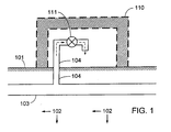
- FIG. 1 for a layout of a conventional water supply piping and a piping of a building, wherein,
- a preferred thermal energy transmission system has a cladding chamber structure for temperature equilibration provided to the ground or underground water supply piping of a water supply system.
- the thermal energy carried by the water current in the water supply piping flows to another gaseous or liquid state fluid of the subject matter into an open space, building, or other closed or semi-closed structure of the subject matter for temperature equilibration to perform the indirect transmission of thermal energy for the purpose of temperature equilibration.
- Fig. 2 shows a schematic view of a preferred embodiment of the present invention, wherein a system of a cladding chamber structure for temperature equilibration is provided to perform open fluid circulation to an open space.
- the system includes a cladding chamber structure 220 for temperature equilibration disposed at where surrounds a certain section of the underground water pipe 103 of the water supply system buried in a deep stratum 102; both end surfaces are closed to the cladding chamber structure 220 for temperature equilibration.
- One or a plurality of fluid inlet 218 and a fluid piping 221 leading to an open space above the surface 101 of the earth are disposed at one end in the vicinity of the closed end surface; one or a plurality of fluid outlet 219 and a fluid piping 231 leading to the open space are disposed on the other end of the cladding chamber structure 220 to allow the gaseous or liquid state fluid flowing in and out.
- the fluid may perform convection circulation by the effects that the cooler descends and the hotter ascends, or driven by a motor with the installation of a liquid pump 123, or driven by other mechanical kinetics or by manual so to pump the fluid passing through the cladding chamber structure 220 into the fluid piping 221 to the open space.
- the fluid in the open space flows through the fluid piping 231 back to the cladding chamber structure 220 so to perform the temperature equilibration transmission of indirect conduction of thermal energy between the water supply system and the open space.
- the fluid piping 221 and another fluid piping 231 are respectively leading to the open space to perform the open fluid circulation; and the optional filtration device 124 may be each disposed to the fluid inlet and outlet of the fluid piping 221 and another fluid piping 231.
- Fig. 3 shows a schematic view of another preferred embodiment yet of the present invention, wherein the system includes the cladding chamber structure for temperature equilibration to perform open fluid circulation to an interior space in a building or other closed or semi-closed structure.
- the system includes a cladding chamber structure 220 for temperature equilibration disposed at where surrounds a certain section of the underground water pipe 103 of the water supply system; both end surfaces are closed to the cladding chamber structure 220 for temperature equilibration.
- One or a plurality of fluid inlet 218 and the fluid piping 221 leading to the space inside the closed or semi-closed structure in the building 110 are disposed at one end in the vicinity of the closed end surface; one or a plurality of fluid outlet 219 and a fluid piping 231 leading to the space inside the closed or semi-closed structure in the building 110 are disposed on the other end of the cladding chamber structure 220 to allow the gaseous or liquid state fluid flowing in and out.
- the fluid may perform convection circulation by the effects that the cooler descends and the hotter ascends, or driven by a motor with the installation of a liquid pump 123, or driven by other mechanical kinetics or by manual so to pump the fluid passing through the cladding chamber structure 220 into the fluid piping 221 to the space inside the building 110 or other closed or semi-closed structure.
- the fluid then flows through the fluid piping 231 back to the cladding chamber structure 220 so to perform the temperature equilibration transmission of indirect conduction of thermal energy between the water supply system and the space inside the building 110 or other closed or semi-closed structure.
- the fluid piping 221 and another fluid piping 231 are respectively leading to the interior space in the building 110 or other closed or semi-closed structure to perform the open fluid circulation; and the optional filtration device 124 may be each disposed to the fluid inlet and outlet of the fluid piping 221 and another fluid piping 231.
- Fig. 4 shows a schematic view of another preferred embodiment yet of the present invention, wherein the system includes the cladding chamber structure for temperature equilibration to perform closed fluid circulation to an open space.
- the system includes a cladding chamber structure 220 for temperature equilibration disposed at where surrounds a certain section of the underground water pipe 103 of the water supply system; both end surfaces are closed to the cladding chamber structure 220 for temperature equilibration.
- One or a plurality of fluid inlet 218 and the fluid piping 221 leading to the open space are disposed at one end in the vicinity of the closed end surface; one or a plurality of fluid outlet 219 and a fluid piping 231 leading to the open space are disposed on the other end of the cladding chamber structure 220 to allow the gaseous or liquid state fluid flowing in and out.
- the fluid may perform convection circulation by the effects that the cooler descends and the hotter ascends, or driven by a motor with the installation of a liquid pump 123, or driven by other mechanical kinetics or by manual so to pump the fluid passing through the cladding chamber structure 220 into the fluid piping 221 to the temperature equilibrating installation 122 disposed in the open space.
- the fluid then flows through the fluid piping 231 back to the cladding chamber structure 220 so to perform the temperature equilibration transmission of indirect conduction of thermal energy between the water supply system and the open space through temperature equilibrating installation 122.
- the fluid piping 221 and another fluid piping 231 are respectively leading to the temperature equilibrating installation 122 disposed in the open space to perform the closed fluid circulation for transmission of temperature equilibration.
- Fig. 5 shows a schematic view of another preferred embodiment yet of the present invention, wherein the system includes the cladding chamber structure for temperature equilibration to perform closed fluid circulation to an interior space in a building or other closed or semi-closed structure.
- the system includes a cladding chamber structure 220 for temperature equilibration disposed at where surrounds a certain section of the underground water pipe 103 of the water supply system; both end surfaces are closed to the cladding chamber structure 220 for temperature equilibration.
- One or a plurality of fluid inlet 218 and the fluid piping 221 leading to the interior space in a building 110 or a closed or semi-closed structure are disposed at one end in the vicinity of the closed end surface; one or a plurality of fluid outlet 219 and a fluid piping 231 leading to the interior space in a building 110 or a closed or semi-closed structure are disposed on the other end of the cladding chamber structure 220 to allow the gaseous or liquid state fluid flowing in and out.
- the fluid may perform convection circulation by the effects that the cooler descends and the hotter ascends, or driven by a motor with the installation of a liquid pump 123, or driven by other mechanical kinetics or by manual so to pump the fluid passing through the cladding chamber structure 220 into the fluid piping 221 to the temperature equilibrating installation 122 disposed in the interior space in the building 110 or other closed or semi-closed structure.
- the fluid then flows through the fluid piping 231 back to the cladding chamber structure 220 so to perform the temperature equilibration transmission of indirect conduction of thermal energy between the water supply system and the interior space in the building 110 or other closed or semi-closed structure through the temperature equilibrating installation 122.
- the fluid piping 221 and another fluid piping 231 are respectively leading to the temperature equilibrating installation 122 disposed in the interior space in the building 110 or other closed or semi-closed structure to perform the closed fluid circulation for transmission of temperature equilibration.
- the subject matter for the temperature equilibration operation performed by the methodology and installation of temperature equilibration with a water supply system of the present invention includes:
- the building referred in these preferred embodiments described above for the methodology and installation of temperature equilibration with a water supply system of the present invention includes house, warehouse, or any building in column or any other geometric form, or any other designated building comprised of a semi-closed or closed structure designed as desired. Other functioning for the general house to live in, the interior space may be further operated to accommodate:
- the natural thermal energy from the water supply system either cools or maintains the installations and facilities in a certain range of temperature.
- the methodology and installation of temperature equilibration with a water supply system of the present invention by operating on the natural thermal energy (ranging between 12 ⁇ 16 °C) in the stratum absorbed by the underground water pipe of an existing water supply system to have current as a carrier to flow through a pipe disposed at where closer to the surface of the earth, exposed from the ground or in a building to execute heat transmission of temperature equilibration to offer lower cost, summary work, and precise function; therefore, this application for a patent is duly filed.
Landscapes
- Engineering & Computer Science (AREA)
- Mechanical Engineering (AREA)
- General Engineering & Computer Science (AREA)
- Life Sciences & Earth Sciences (AREA)
- Physics & Mathematics (AREA)
- Thermal Sciences (AREA)
- Chemical & Material Sciences (AREA)
- Combustion & Propulsion (AREA)
- Sustainable Energy (AREA)
- Sustainable Development (AREA)
- Structural Engineering (AREA)
- Health & Medical Sciences (AREA)
- Hydrology & Water Resources (AREA)
- Public Health (AREA)
- Water Supply & Treatment (AREA)
- Other Air-Conditioning Systems (AREA)
- Greenhouses (AREA)
- Domestic Plumbing Installations (AREA)
Abstract
Description
- The present invention is related to a methodology and installation for temperature equilibrating conduction, and more particularly, to the use of specific piping from a water supply system and the water running in the pipe as a carrier to conduct the thermal energy in the stratum to a subject matter on the ground.
- Whereas reliance upon air conditioning system in summer time in conventional buildings and upon electric power or fuel for heating purpose in winter time consume massive energy source. Furthermore, in bitter cold days, frozen water pipe of the conventional water supply system exposed or buried just beneath the surface of the earth, accumulation of snow on roof and frozen road are often blamed for causing disasters.
-
DE 2834442 discloses a method of heating a building using heat extracted from a central water supply, the pipe of which includes an underground portion. - The primary purpose of the present invention is to provide a methodology and installation to execute temperature equilibration thermal transmission between the thermal energy in the deeper stratum and a subject matter on the ground designated for transmission of thermal energy by a closed piping comprised of underground water pipe buried in the underground for a water supply system and piping disposed on the ground to transmit the thermal energy in the stratum conducted by the underground pipe through the current running in the piping. More particularly, the invention provides a thermal energy transmission system as set out below in claim 1. Preferred features of the invention include those contained in the accompanying dependent claims.
-
-
Fig. 1 is a schematic view showing a layout of a conventional water supply piping and a piping in a building. -
Fig. 2 is a schematic view of a thermal energy transmission system in accordance with the present invention to perform open fluid circulation to an open space. -
Fig. 3 is a schematic view of a second thermal energy transmission system in accordance with the invention to perform open fluid circulation to an interior space in a building or other closed or semi-closed structure. -
Fig. 4 is a schematic view of a third thermal energy transmission system in accordance with the invention to perform closed fluid circulation to an open space. -
Fig. 5 is a schematic view of a fourth thermal energy transmission system in accordance with the invention to perform closed fluid circulation to an interior space in a building or other closed or semi-closed structure. - In accordance with the present invention, methodology and installation for temperature equilibration by means of a water supply system operates on having an underground water pipe of the conventional water supply system buried in the stratum and water running in the pipe as carriers to be incorporated with a flow passage comprised of a pipe constructed on the ground, a temperature equilibrating object, and a pump. Whereas it is a well-known fact that the stratum 4~6 meters below the surface of the earth maintains a normal temperature range between 12~6 °C all year round, the current pumped by the pump, or the circulating current resulted from the convection effect due to temperature difference when the hotter water runs to the cooler water and vice versa, or the current resulted from shunting effect, functions in systems described hereinafter as a carrier of thermal energy to execute thermal transmission of temperature equilibration between the thermal energy in the stratum and a subject matter on ground to receive the thermal energy transmission, thus to replace or support the conventional air conditioning system that consumes massive energy and further to save energy.
- Referring to
Fig. 1 for a layout of a conventional water supply piping and a piping of a building, wherein, - --- 101 relates to the surface of the earth;
- --- 102 relates to a deeper stratum where the normal temperature maintains within the range of 12~16 °C;
- --- 103 relates to an underground water pipe of a conventional water supply system buried in the
deeper stratum 102; - --- 104 relates to a water supply branch to be connected to where between a
water valve 111 at the subscriber's and theunderground water pipe 103 to deliver water from the water supply system to the subscriber; and - --- 111 relates to the water valve at the subscriber's
building 110 that serves as a flow switch to fetch the water at random. - Within the layout as described above, the following problems often take place in bitter cold winter:
- (1) The water inside the conventional
water supply branch 104 that is closer to the surface of theearth 101 or that is exposed from the surface of theearth 101 is vulnerable to get frozen in bitter cold winter thus to block the current; and - (2) The roof of the building is sometimes threatened by collapse due to the weight and pressure imposed by accumulated snow or ice thereon.
- Referring to the drawings, a preferred thermal energy transmission system has a cladding chamber structure for temperature equilibration provided to the ground or underground water supply piping of a water supply system. Indirectly through the interior of the cladding chamber, the thermal energy carried by the water current in the water supply piping flows to another gaseous or liquid state fluid of the subject matter into an open space, building, or other closed or semi-closed structure of the subject matter for temperature equilibration to perform the indirect transmission of thermal energy for the purpose of temperature equilibration.
-
Fig. 2 shows a schematic view of a preferred embodiment of the present invention, wherein a system of a cladding chamber structure for temperature equilibration is provided to perform open fluid circulation to an open space. - The system includes a
cladding chamber structure 220 for temperature equilibration disposed at where surrounds a certain section of theunderground water pipe 103 of the water supply system buried in adeep stratum 102; both end surfaces are closed to thecladding chamber structure 220 for temperature equilibration. One or a plurality offluid inlet 218 and afluid piping 221 leading to an open space above thesurface 101 of the earth are disposed at one end in the vicinity of the closed end surface; one or a plurality offluid outlet 219 and afluid piping 231 leading to the open space are disposed on the other end of thecladding chamber structure 220 to allow the gaseous or liquid state fluid flowing in and out. The fluid may perform convection circulation by the effects that the cooler descends and the hotter ascends, or driven by a motor with the installation of aliquid pump 123, or driven by other mechanical kinetics or by manual so to pump the fluid passing through thecladding chamber structure 220 into thefluid piping 221 to the open space. The fluid in the open space flows through thefluid piping 231 back to thecladding chamber structure 220 so to perform the temperature equilibration transmission of indirect conduction of thermal energy between the water supply system and the open space. Thefluid piping 221 and anotherfluid piping 231 are respectively leading to the open space to perform the open fluid circulation; and theoptional filtration device 124 may be each disposed to the fluid inlet and outlet of thefluid piping 221 and anotherfluid piping 231. -
Fig. 3 shows a schematic view of another preferred embodiment yet of the present invention, wherein the system includes the cladding chamber structure for temperature equilibration to perform open fluid circulation to an interior space in a building or other closed or semi-closed structure. - The system includes a
cladding chamber structure 220 for temperature equilibration disposed at where surrounds a certain section of theunderground water pipe 103 of the water supply system; both end surfaces are closed to thecladding chamber structure 220 for temperature equilibration. One or a plurality offluid inlet 218 and thefluid piping 221 leading to the space inside the closed or semi-closed structure in thebuilding 110 are disposed at one end in the vicinity of the closed end surface; one or a plurality offluid outlet 219 and afluid piping 231 leading to the space inside the closed or semi-closed structure in thebuilding 110 are disposed on the other end of thecladding chamber structure 220 to allow the gaseous or liquid state fluid flowing in and out. The fluid may perform convection circulation by the effects that the cooler descends and the hotter ascends, or driven by a motor with the installation of aliquid pump 123, or driven by other mechanical kinetics or by manual so to pump the fluid passing through thecladding chamber structure 220 into thefluid piping 221 to the space inside thebuilding 110 or other closed or semi-closed structure. The fluid then flows through thefluid piping 231 back to thecladding chamber structure 220 so to perform the temperature equilibration transmission of indirect conduction of thermal energy between the water supply system and the space inside thebuilding 110 or other closed or semi-closed structure. Thefluid piping 221 and anotherfluid piping 231 are respectively leading to the interior space in thebuilding 110 or other closed or semi-closed structure to perform the open fluid circulation; and theoptional filtration device 124 may be each disposed to the fluid inlet and outlet of thefluid piping 221 and anotherfluid piping 231. -
Fig. 4 shows a schematic view of another preferred embodiment yet of the present invention, wherein the system includes the cladding chamber structure for temperature equilibration to perform closed fluid circulation to an open space. - The system includes a
cladding chamber structure 220 for temperature equilibration disposed at where surrounds a certain section of theunderground water pipe 103 of the water supply system; both end surfaces are closed to thecladding chamber structure 220 for temperature equilibration. One or a plurality offluid inlet 218 and thefluid piping 221 leading to the open space are disposed at one end in the vicinity of the closed end surface; one or a plurality offluid outlet 219 and afluid piping 231 leading to the open space are disposed on the other end of thecladding chamber structure 220 to allow the gaseous or liquid state fluid flowing in and out. The fluid may perform convection circulation by the effects that the cooler descends and the hotter ascends, or driven by a motor with the installation of aliquid pump 123, or driven by other mechanical kinetics or by manual so to pump the fluid passing through thecladding chamber structure 220 into thefluid piping 221 to the temperature equilibratinginstallation 122 disposed in the open space. The fluid then flows through thefluid piping 231 back to thecladding chamber structure 220 so to perform the temperature equilibration transmission of indirect conduction of thermal energy between the water supply system and the open space through temperature equilibratinginstallation 122. Thefluid piping 221 and anotherfluid piping 231 are respectively leading to the temperature equilibratinginstallation 122 disposed in the open space to perform the closed fluid circulation for transmission of temperature equilibration. -
Fig. 5 shows a schematic view of another preferred embodiment yet of the present invention, wherein the system includes the cladding chamber structure for temperature equilibration to perform closed fluid circulation to an interior space in a building or other closed or semi-closed structure. - The system includes a
cladding chamber structure 220 for temperature equilibration disposed at where surrounds a certain section of theunderground water pipe 103 of the water supply system; both end surfaces are closed to thecladding chamber structure 220 for temperature equilibration. One or a plurality offluid inlet 218 and thefluid piping 221 leading to the interior space in abuilding 110 or a closed or semi-closed structure are disposed at one end in the vicinity of the closed end surface; one or a plurality offluid outlet 219 and afluid piping 231 leading to the interior space in abuilding 110 or a closed or semi-closed structure are disposed on the other end of thecladding chamber structure 220 to allow the gaseous or liquid state fluid flowing in and out. The fluid may perform convection circulation by the effects that the cooler descends and the hotter ascends, or driven by a motor with the installation of aliquid pump 123, or driven by other mechanical kinetics or by manual so to pump the fluid passing through thecladding chamber structure 220 into thefluid piping 221 to the temperature equilibratinginstallation 122 disposed in the interior space in thebuilding 110 or other closed or semi-closed structure. The fluid then flows through thefluid piping 231 back to thecladding chamber structure 220 so to perform the temperature equilibration transmission of indirect conduction of thermal energy between the water supply system and the interior space in thebuilding 110 or other closed or semi-closed structure through the temperature equilibratinginstallation 122. Thefluid piping 221 and anotherfluid piping 231 are respectively leading to the temperature equilibratinginstallation 122 disposed in the interior space in thebuilding 110 or other closed or semi-closed structure to perform the closed fluid circulation for transmission of temperature equilibration. - The subject matter for the temperature equilibration operation performed by the methodology and installation of temperature equilibration with a water supply system of the present invention includes:
- (1) Various types of open space; or
- (2) Open space on the surface of earth; or
- (3) Shallow stratum; or
- (4) Interior space of a semi-closed or closed building; or
- (5) Interior space of other semi-closed or closed structure.
- The building referred in these preferred embodiments described above for the methodology and installation of temperature equilibration with a water supply system of the present invention includes house, warehouse, or any building in column or any other geometric form, or any other designated building comprised of a semi-closed or closed structure designed as desired. Other functioning for the general house to live in, the interior space may be further operated to accommodate:
- (1) Tooling machine, test and inspection instruments, observation instruments, industrial facilities, mechanical facilities, power machineries, and electro-mechanical facilities that demands specific working temperature; or
- (2) Cooling installations, electricity storage installations; or
- (3) Storage of solid, liquid, or gaseous state chemicals.
- With the present invention, the natural thermal energy from the water supply system either cools or maintains the installations and facilities in a certain range of temperature.
- Accordingly, the methodology and installation of temperature equilibration with a water supply system of the present invention by operating on the natural thermal energy (ranging between 12~16 °C) in the stratum absorbed by the underground water pipe of an existing water supply system to have current as a carrier to flow through a pipe disposed at where closer to the surface of the earth, exposed from the ground or in a building to execute heat transmission of temperature equilibration to offer lower cost, summary work, and precise function; therefore, this application for a patent is duly filed.
Claims (11)
- A thermal energy transmission system comprising an underground water pipe (103) and a fluid circulation structure, the underground water pipe (103) forming part of a conventional water supply system and being buried in a deep stratum (102) which maintains a normal temperature within a predetermined range over a long period of time, the fluid circulation structure being arranged and configured to transfer thermal energy from the water in the underground water pipe (103) to a region above the ground, or to transfer thermal energy from a region above the ground to the water in the underground pipe (103), characterized in that a cladding chamber structure (220) for temperature equilibration is disposed around a certain section of the underground water pipe (103), the transfer of thermal energy being effected by a fluid circulating in the fluid circulation structure,
wherein one or a plurality of fluid inlet (218) and a fluid piping (221) leading to said region above the ground are disposed at one end of the cladding chamber structure (220) in the vicinity of the closed end surface and one or a plurality of fluid outlet (219) and a fluid piping (231) leading to said region above the ground are disposed on the other end of the cladding chamber structure (220) to allow the fluid to flow in and out. - A system as claimed in claim 1, wherein the cladding chamber structure (220) surrounds a portion of the underground water pipe.
- A system as claimed in claim 1 or claim 2, further comprising a temperature equilibrating installation (122) associated with the cladding chamber structure (220).
- A system as claimed in claim 1, wherein both end surfaces of the cladding chamber structure (220) being closed for temperature equilibration; the fluid performing convection circulation as a result of cooler fluid descending and hotter fluid ascending, or is driven by a motor with the installation of a pump (123), or driven by other mechanical kinetics or by manual energy so to pump the fluid passing through the cladding chamber structure (220) into the fluid piping (221) to the region above the ground; the fluid in the region above the ground flowing through the fluid piping (231) back to the cladding chamber structure (220) so to perform the temperature equilibration transmission of indirect conduction of thermal energy between the water supply system and the region above the ground; the fluid piping (221) and another fluid piping (231) respectively leading to the region above the ground to perform the fluid circulation; and an optional filtration device (124) may be disposed at each of the fluid inlet and outlet of the fluid piping (221) and the other fluid piping (231).
- A system as claimed in claim 1, the system including a cladding chamber structure (220) for temperature equilibration disposed to surround a certain section of the underground water pipe (103) of the water supply system; both end surfaces of the cladding chamber structure (220) being closed for temperature equilibration; the fluid performing convection circulation as a result of cooler fluid descending and hotter fluid ascending, or is driven by a motor with the installation of a pump (123), or driven by other mechanical kinetics or by manual energy so as to pump the fluid passing through the cladding chamber structure (220) into the fluid piping (221) to a space inside a building (110) or other closed or semi-closed structure; the fluid then flowing through the fluid piping (231) back to the cladding chamber structure (220) so to perform temperature equilibration transmission of indirect conduction of thermal energy between the water supply system and the space inside the building (110) or other closed or semi-closed structure; the fluid piping (221) and another fluid piping (231) respectively leading to the interior space in the building (110) or other closed or semi-closed structure to perform fluid circulation; and an optional filtration device 124 may be disposed at each of the fluid inlet and outlet of the fluid piping (221) and the other fluid piping (231).
- A system as claimed in claim 1, the system including a cladding chamber structure (220) for temperature equilibration disposed to surround a certain section of the underground water pipe (103) of the water supply system; both end surfaces of the cladding chamber structure (220) being closed for temperature equilibration; the fluid performing convection circulation as a result of cooler fluid descending and hotter fluid ascending, or is driven by a motor with the installation of a pump (123), or driven by other mechanical kinetics or by manual energy so to pump the fluid passing through the cladding chamber structure (220) into the fluid piping (221) to a temperature equilibrating installation (122) disposed in the region above the ground; the fluid then flowing through the fluid piping (231) back to the cladding chamber structure (220) so to perform temperature equilibration transmission by indirect conduction of thermal energy between the water supply system and the region above the ground through a temperature equilibrating installation (122); the fluid piping (221) and another fluid piping (231) respectively leading to the temperature equilibration device (122) disposed in the region above the ground to perform fluid circulation for transmission of temperature equilibration.
- A system as claimed in claim 1, the system including a cladding chamber structure (220) for temperature equilibration disposed to surround a certain section of the underground water pipe (103) of the water supply system; both end surfaces of the cladding chamber structure (220) being closed for temperature equilibration; the fluid performing convection circulation as a result of cooler fluid descending and hotter fluid ascending, or is driven by a motor with the installation of a pump (123), or driven by other mechanical kinetics or by manual energy so to pump the fluid passing through the cladding chamber structure (220) into the fluid piping (221) to a temperature equilibrating installation (122) disposed in an interior space in a building (110) or other closed or semi-closed structure; the fluid then flowing through the fluid piping (231) back to the cladding chamber structure (220) so to perform temperature equilibration transmission by indirect conduction of thermal energy between the water supply system and the interior space in the building (110) or other closed or semi-closed structure through a temperature equilibrating installation (122); the fluid piping (221) and another fluid piping (231) respectively leading to the temperature equilibrating installation (122) disposed in the interior space in the building (110) or other closed or semi-closed structure to perform the fluid circulation for transmission of temperature equilibration.
- A system as claimed in any one of the preceding claims, wherein the system includes:(1) various types of regions above the ground; or(2) regions above the ground on the surface of earth; or(3) a shallow stratum; or(4) an interior space of a semi-closed nature; or(5) a closed building or interior space of other semi-closed or closed structure.
- A system as claimed in any one of claims 5, 7 and 8, wherein the building includes a house, a warehouse, or any building in column or any other geometric form, or any other designated building comprised of a semi-closed or closed structure; or functioning as a general house to live in, the interior space may be further operated to accommodate.(1) industrial facilities, mechanical facilities, power machineries, and electro-mechanical facilities that demand a specific working temperature; or(2) cooling installations, electricity storage installations; or(3) storage of solid, liquid, or gaseous state chemicals; the natural thermal energy from the water supply system either cooling or maintaining the installations and facilities in a certain range of temperature.
- A system as claimed in claim 1, wherein the fluid circulation structure comprises an open structure; wherein a pair of conduits are fixed to the cladding chamber structure in such a manner that each has one end in fluid communication with the interior of the cladding chamber structure, the other ends of the conduits being open and terminating in said region, said other ends of the conduits constituting respectively a fluid entrance to, and a fluid exit from, said region.
- A system as claimed in claim 1, wherein the fluid circulation structure comprises a closed structure.
Priority Applications (9)
| Application Number | Priority Date | Filing Date | Title |
|---|---|---|---|
| US11/489,542 US20080028761A1 (en) | 2006-05-30 | 2006-07-20 | Temperature equilibrating methodology & installation with water supply system |
| ES07252249.3T ES2448490T3 (en) | 2007-06-04 | 2007-06-04 | Methodology and installation for temperature balancing with a water supply system |
| EP11173696.3A EP2383525B1 (en) | 2007-06-04 | 2007-06-04 | Temperature equilibrating methodology & installation with water supply system |
| ES11173696.3T ES2445740T3 (en) | 2007-06-04 | 2007-06-04 | Methodology and installation for temperature balancing with a water supply system |
| EP07252249.3A EP2000743B1 (en) | 2007-06-04 | 2007-06-04 | Temperature equilibrating methodology and installation with water supply system |
| TW096125322A TWI534398B (en) | 2007-06-04 | 2007-07-10 | Temperature equilibrating installation with water supply system |
| CN200710139064XA CN101354153B (en) | 2007-06-04 | 2007-07-24 | A device for uniform temperature through the water supply system |
| KR1020070085360A KR20090020785A (en) | 2007-06-04 | 2007-08-24 | Method and apparatus for uniform temperature by water supply system |
| JP2007220209A JP2009052293A (en) | 2007-06-04 | 2007-08-27 | Method and apparatus for uniforming temperature by water supply system |
Applications Claiming Priority (1)
| Application Number | Priority Date | Filing Date | Title |
|---|---|---|---|
| EP07252249.3A EP2000743B1 (en) | 2007-06-04 | 2007-06-04 | Temperature equilibrating methodology and installation with water supply system |
Related Child Applications (1)
| Application Number | Title | Priority Date | Filing Date |
|---|---|---|---|
| EP11173696.3 Division-Into | 2011-07-12 |
Publications (2)
| Publication Number | Publication Date |
|---|---|
| EP2000743A1 EP2000743A1 (en) | 2008-12-10 |
| EP2000743B1 true EP2000743B1 (en) | 2013-12-18 |
Family
ID=38611099
Family Applications (2)
| Application Number | Title | Priority Date | Filing Date |
|---|---|---|---|
| EP11173696.3A Not-in-force EP2383525B1 (en) | 2007-06-04 | 2007-06-04 | Temperature equilibrating methodology & installation with water supply system |
| EP07252249.3A Not-in-force EP2000743B1 (en) | 2006-05-30 | 2007-06-04 | Temperature equilibrating methodology and installation with water supply system |
Family Applications Before (1)
| Application Number | Title | Priority Date | Filing Date |
|---|---|---|---|
| EP11173696.3A Not-in-force EP2383525B1 (en) | 2007-06-04 | 2007-06-04 | Temperature equilibrating methodology & installation with water supply system |
Country Status (7)
| Country | Link |
|---|---|
| US (1) | US20080028761A1 (en) |
| EP (2) | EP2383525B1 (en) |
| JP (1) | JP2009052293A (en) |
| KR (1) | KR20090020785A (en) |
| CN (1) | CN101354153B (en) |
| ES (2) | ES2448490T3 (en) |
| TW (1) | TWI534398B (en) |
Families Citing this family (6)
| Publication number | Priority date | Publication date | Assignee | Title |
|---|---|---|---|---|
| US20100018672A1 (en) * | 2008-07-22 | 2010-01-28 | Tai-Her Yang | Conducting type inter-piping fluid thermal energy transfer device |
| US8448876B2 (en) * | 2009-06-12 | 2013-05-28 | Tai-Her Yang | Semiconductor application installation adapted with a temperature equalization system |
| JP5388131B2 (en) * | 2010-04-20 | 2014-01-15 | 典政 佐々木 | Solar thermal underground thermal storage device using solar heat |
| JP5028638B1 (en) * | 2011-08-09 | 2012-09-19 | 中村物産有限会社 | Geothermal utilization structure and geothermal heat exchanger buried structure |
| US20130042997A1 (en) * | 2011-08-15 | 2013-02-21 | Tai-Her Yang | Open-loopnatural thermal energy releasing system wtih partialreflux |
| US11129341B2 (en) * | 2014-04-09 | 2021-09-28 | Roots Sustainable Agricultural Technologies Ltd. | Heat delivery system and method |
Family Cites Families (29)
| Publication number | Priority date | Publication date | Assignee | Title |
|---|---|---|---|---|
| US508654A (en) * | 1893-11-14 | Cooling transformers | ||
| US827025A (en) * | 1904-04-20 | 1906-07-24 | George Thomas Liddle | Device for thawing frosted fire-hydrants, water-mains, and service-pipes from mains to house-hydrants. |
| US862593A (en) * | 1907-03-05 | 1907-08-06 | Charles C Steiner | Fire-hydrant. |
| DE2834442A1 (en) * | 1978-08-05 | 1980-02-14 | Ernst Wilhelm Guenther | Heat pump for household water heating - draws heat from water supply mains as indirect ground heat carrier |
| US4279294A (en) * | 1978-12-22 | 1981-07-21 | United Technologies Corporation | Heat pipe bag system |
| DE2930484A1 (en) * | 1979-07-27 | 1981-02-12 | Nikolaus Thiel | Central heating system using heat pump - has heat exchangers on buried water supply line to extract heat for evaporators |
| JPS5816852U (en) * | 1981-07-26 | 1983-02-02 | ナショナル住宅産業株式会社 | Equipment that utilizes underground temperature |
| JPS608754U (en) * | 1983-06-29 | 1985-01-22 | 小沢コンクリ−ト工業株式会社 | Water pipe arrangement structure |
| US4497365A (en) * | 1983-08-15 | 1985-02-05 | John Boyer | Heat exchanger |
| JPS6122193A (en) * | 1984-07-05 | 1986-01-30 | Showa Alum Corp | Long heat pipe |
| JPS639646Y2 (en) * | 1984-12-28 | 1988-03-22 | ||
| JPS61193170U (en) * | 1985-05-21 | 1986-12-01 | ||
| US4880051A (en) * | 1986-07-14 | 1989-11-14 | Kabushiki Kaisha Patine Shokai | Piping apparatus for melting snow and ice |
| JPH0746036B2 (en) * | 1987-06-16 | 1995-05-17 | 関西電力株式会社 | Geothermal heat pipe performance inspection method |
| JPS645058U (en) * | 1987-06-26 | 1989-01-12 | ||
| US5339893A (en) * | 1992-05-08 | 1994-08-23 | The United States Of America As Represented By The Secretary Of The Army | Apparatus for containing toxic spills employing hybrid thermosyphons |
| JPH07224449A (en) * | 1994-02-10 | 1995-08-22 | Fujikura Ltd | Antifreeze structure for water pipes |
| JPH0833175A (en) * | 1994-07-11 | 1996-02-02 | Fujikura Ltd | Cable cave cooling structure |
| US5727621A (en) * | 1995-12-26 | 1998-03-17 | Geotech, Llc (A Non-Incorporated Company) | Geothermal energy means and procedure |
| JPH11256540A (en) * | 1998-03-11 | 1999-09-21 | Kubota Corp | Prevention of road surface freezing using sewage pipes, snow melting method |
| US6053239A (en) * | 1998-09-04 | 2000-04-25 | Hardin Geotechnologies, Llc. | Geothermal energy means and procedure |
| JP3036634B1 (en) * | 1998-11-13 | 2000-04-24 | 鹿島建設株式会社 | District heating and cooling system with distributed heat pump device |
| JP3315381B2 (en) * | 1999-08-24 | 2002-08-19 | 株式会社金正陶器 | Water storage tank |
| US6267172B1 (en) * | 2000-02-15 | 2001-07-31 | Mcclung, Iii Guy L. | Heat exchange systems |
| JP3485180B2 (en) * | 2001-03-02 | 2004-01-13 | 芳明 佐々木 | Water supply and drainage freezing prevention equipment in buildings |
| JP2003027534A (en) * | 2001-07-19 | 2003-01-29 | Masao Fujita | Apparatus for holding city water at room temperature |
| JP4046687B2 (en) * | 2001-08-01 | 2008-02-13 | ロナルド・エス・エース | Air-conditioning system using geothermal heat |
| US20040108096A1 (en) * | 2002-11-27 | 2004-06-10 | Janssen Terrance Ernest | Geothermal loopless exchanger |
| CA2541378C (en) * | 2005-03-25 | 2008-02-19 | Richard Laroche | Geothermal aqueduct network |
-
2006
- 2006-07-20 US US11/489,542 patent/US20080028761A1/en not_active Abandoned
-
2007
- 2007-06-04 EP EP11173696.3A patent/EP2383525B1/en not_active Not-in-force
- 2007-06-04 EP EP07252249.3A patent/EP2000743B1/en not_active Not-in-force
- 2007-06-04 ES ES07252249.3T patent/ES2448490T3/en active Active
- 2007-06-04 ES ES11173696.3T patent/ES2445740T3/en active Active
- 2007-07-10 TW TW096125322A patent/TWI534398B/en active
- 2007-07-24 CN CN200710139064XA patent/CN101354153B/en active Active
- 2007-08-24 KR KR1020070085360A patent/KR20090020785A/en not_active Withdrawn
- 2007-08-27 JP JP2007220209A patent/JP2009052293A/en active Pending
Also Published As
| Publication number | Publication date |
|---|---|
| EP2383525B1 (en) | 2013-11-27 |
| JP2009052293A (en) | 2009-03-12 |
| CN101354153B (en) | 2013-04-17 |
| TW200902923A (en) | 2009-01-16 |
| EP2000743A1 (en) | 2008-12-10 |
| ES2448490T3 (en) | 2014-03-14 |
| US20080028761A1 (en) | 2008-02-07 |
| EP2383525A1 (en) | 2011-11-02 |
| ES2445740T3 (en) | 2014-03-05 |
| KR20090020785A (en) | 2009-02-27 |
| TWI534398B (en) | 2016-05-21 |
| CN101354153A (en) | 2009-01-28 |
Similar Documents
| Publication | Publication Date | Title |
|---|---|---|
| US11041633B2 (en) | District thermal energy distribution system | |
| EP2000743B1 (en) | Temperature equilibrating methodology and installation with water supply system | |
| US11041634B2 (en) | Local thermal energy consumer assembly and a local thermal energy generator assembly for a district thermal energy distribution system | |
| CN110603410B (en) | Regional energy distribution system | |
| RU2486416C2 (en) | Network for heating and cooling of buildings | |
| US20040108096A1 (en) | Geothermal loopless exchanger | |
| US20130037236A1 (en) | Geothermal facility with thermal recharging of the subsoil | |
| EP3184914A1 (en) | A thermal server plant and a method for controlling the same | |
| CN201161766Y (en) | Constant temperature water tank | |
| EP2641034B1 (en) | Closed-loop geothermal probe | |
| WO2008009289A1 (en) | A heat exchange module, in particular for a ground source heat pump | |
| EP3593054B1 (en) | A local thermal energy consumer assembly and a local thermal energy generator assembly for a district thermal energy distribution system | |
| KR101337353B1 (en) | Heat pump system using water for irrigation of golf course reservoir | |
| RU140779U1 (en) | HEAT SUPPLY SYSTEM | |
| US20070295829A1 (en) | Temperature equilibrating methodology & installation with water supply system | |
| KR101174205B1 (en) | Energy production apparatus by sewage water and heat pump | |
| PL225387B1 (en) | Ground-air heat exchanger | |
| EP4019853A1 (en) | Thermal energy balancing device | |
| KR100305010B1 (en) | Heat exchange heater using hot spring water | |
| Vermeer et al. | Earth Cooling Tubes | |
| KR20160020612A (en) | Temperature control system for road using flexible heat exchanging pipe | |
| KR20100030712A (en) | Cooling and heating system using underground water | |
| CZ17096U1 (en) | Cooling system, particularly for underground mines | |
| HK1155799B (en) | Heating and cooling network for buildings | |
| KR20120081715A (en) | Open cooling and heating and cool and hot water system using ground source |
Legal Events
| Date | Code | Title | Description |
|---|---|---|---|
| PUAI | Public reference made under article 153(3) epc to a published international application that has entered the european phase |
Free format text: ORIGINAL CODE: 0009012 |
|
| AK | Designated contracting states |
Kind code of ref document: A1 Designated state(s): AT BE BG CH CY CZ DE DK EE ES FI FR GB GR HU IE IS IT LI LT LU LV MC MT NL PL PT RO SE SI SK TR |
|
| AX | Request for extension of the european patent |
Extension state: AL BA HR MK RS |
|
| 17P | Request for examination filed |
Effective date: 20090609 |
|
| 17Q | First examination report despatched |
Effective date: 20090710 |
|
| AKX | Designation fees paid |
Designated state(s): AT BE BG CH CY CZ DE DK EE ES FI FR GB GR HU IE IS IT LI LT LU LV MC MT NL PL PT RO SE SI SK TR |
|
| DAC | Divisional application: reference to earlier application (deleted) | ||
| REG | Reference to a national code |
Ref country code: DE Ref legal event code: R079 Ref document number: 602007034298 Country of ref document: DE Free format text: PREVIOUS MAIN CLASS: F24F0005000000 Ipc: F28D0001020000 |
|
| RIC1 | Information provided on ipc code assigned before grant |
Ipc: F24J 3/08 20060101ALI20130411BHEP Ipc: F28D 15/00 20060101ALI20130411BHEP Ipc: F28D 1/02 20060101AFI20130411BHEP Ipc: F24F 5/00 20060101ALI20130411BHEP |
|
| GRAP | Despatch of communication of intention to grant a patent |
Free format text: ORIGINAL CODE: EPIDOSNIGR1 |
|
| INTG | Intention to grant announced |
Effective date: 20130726 |
|
| GRAS | Grant fee paid |
Free format text: ORIGINAL CODE: EPIDOSNIGR3 |
|
| GRAA | (expected) grant |
Free format text: ORIGINAL CODE: 0009210 |
|
| AK | Designated contracting states |
Kind code of ref document: B1 Designated state(s): AT BE BG CH CY CZ DE DK EE ES FI FR GB GR HU IE IS IT LI LT LU LV MC MT NL PL PT RO SE SI SK TR |
|
| REG | Reference to a national code |
Ref country code: GB Ref legal event code: FG4D |
|
| REG | Reference to a national code |
Ref country code: CH Ref legal event code: EP |
|
| REG | Reference to a national code |
Ref country code: AT Ref legal event code: REF Ref document number: 645810 Country of ref document: AT Kind code of ref document: T Effective date: 20140115 |
|
| REG | Reference to a national code |
Ref country code: IE Ref legal event code: FG4D |
|
| REG | Reference to a national code |
Ref country code: DE Ref legal event code: R096 Ref document number: 602007034298 Country of ref document: DE Effective date: 20140213 |
|
| REG | Reference to a national code |
Ref country code: NL Ref legal event code: T3 |
|
| REG | Reference to a national code |
Ref country code: ES Ref legal event code: FG2A Ref document number: 2448490 Country of ref document: ES Kind code of ref document: T3 Effective date: 20140314 |
|
| PG25 | Lapsed in a contracting state [announced via postgrant information from national office to epo] |
Ref country code: SE Free format text: LAPSE BECAUSE OF FAILURE TO SUBMIT A TRANSLATION OF THE DESCRIPTION OR TO PAY THE FEE WITHIN THE PRESCRIBED TIME-LIMIT Effective date: 20131218 Ref country code: LT Free format text: LAPSE BECAUSE OF FAILURE TO SUBMIT A TRANSLATION OF THE DESCRIPTION OR TO PAY THE FEE WITHIN THE PRESCRIBED TIME-LIMIT Effective date: 20131218 Ref country code: FI Free format text: LAPSE BECAUSE OF FAILURE TO SUBMIT A TRANSLATION OF THE DESCRIPTION OR TO PAY THE FEE WITHIN THE PRESCRIBED TIME-LIMIT Effective date: 20131218 |
|
| REG | Reference to a national code |
Ref country code: AT Ref legal event code: MK05 Ref document number: 645810 Country of ref document: AT Kind code of ref document: T Effective date: 20131218 |
|
| REG | Reference to a national code |
Ref country code: GR Ref legal event code: EP Ref document number: 20140400529 Country of ref document: GR Effective date: 20140416 |
|
| REG | Reference to a national code |
Ref country code: LT Ref legal event code: MG4D |
|
| PG25 | Lapsed in a contracting state [announced via postgrant information from national office to epo] |
Ref country code: LV Free format text: LAPSE BECAUSE OF FAILURE TO SUBMIT A TRANSLATION OF THE DESCRIPTION OR TO PAY THE FEE WITHIN THE PRESCRIBED TIME-LIMIT Effective date: 20131218 |
|
| PG25 | Lapsed in a contracting state [announced via postgrant information from national office to epo] |
Ref country code: EE Free format text: LAPSE BECAUSE OF FAILURE TO SUBMIT A TRANSLATION OF THE DESCRIPTION OR TO PAY THE FEE WITHIN THE PRESCRIBED TIME-LIMIT Effective date: 20131218 Ref country code: BE Free format text: LAPSE BECAUSE OF FAILURE TO SUBMIT A TRANSLATION OF THE DESCRIPTION OR TO PAY THE FEE WITHIN THE PRESCRIBED TIME-LIMIT Effective date: 20131218 Ref country code: IS Free format text: LAPSE BECAUSE OF FAILURE TO SUBMIT A TRANSLATION OF THE DESCRIPTION OR TO PAY THE FEE WITHIN THE PRESCRIBED TIME-LIMIT Effective date: 20140418 |
|
| PG25 | Lapsed in a contracting state [announced via postgrant information from national office to epo] |
Ref country code: AT Free format text: LAPSE BECAUSE OF FAILURE TO SUBMIT A TRANSLATION OF THE DESCRIPTION OR TO PAY THE FEE WITHIN THE PRESCRIBED TIME-LIMIT Effective date: 20131218 Ref country code: SK Free format text: LAPSE BECAUSE OF FAILURE TO SUBMIT A TRANSLATION OF THE DESCRIPTION OR TO PAY THE FEE WITHIN THE PRESCRIBED TIME-LIMIT Effective date: 20131218 Ref country code: RO Free format text: LAPSE BECAUSE OF FAILURE TO SUBMIT A TRANSLATION OF THE DESCRIPTION OR TO PAY THE FEE WITHIN THE PRESCRIBED TIME-LIMIT Effective date: 20131218 Ref country code: PL Free format text: LAPSE BECAUSE OF FAILURE TO SUBMIT A TRANSLATION OF THE DESCRIPTION OR TO PAY THE FEE WITHIN THE PRESCRIBED TIME-LIMIT Effective date: 20131218 Ref country code: CY Free format text: LAPSE BECAUSE OF FAILURE TO SUBMIT A TRANSLATION OF THE DESCRIPTION OR TO PAY THE FEE WITHIN THE PRESCRIBED TIME-LIMIT Effective date: 20131218 Ref country code: CZ Free format text: LAPSE BECAUSE OF FAILURE TO SUBMIT A TRANSLATION OF THE DESCRIPTION OR TO PAY THE FEE WITHIN THE PRESCRIBED TIME-LIMIT Effective date: 20131218 Ref country code: PT Free format text: LAPSE BECAUSE OF FAILURE TO SUBMIT A TRANSLATION OF THE DESCRIPTION OR TO PAY THE FEE WITHIN THE PRESCRIBED TIME-LIMIT Effective date: 20140418 |
|
| PGFP | Annual fee paid to national office [announced via postgrant information from national office to epo] |
Ref country code: GR Payment date: 20140624 Year of fee payment: 8 |
|
| REG | Reference to a national code |
Ref country code: DE Ref legal event code: R097 Ref document number: 602007034298 Country of ref document: DE |
|
| PLBE | No opposition filed within time limit |
Free format text: ORIGINAL CODE: 0009261 |
|
| STAA | Information on the status of an ep patent application or granted ep patent |
Free format text: STATUS: NO OPPOSITION FILED WITHIN TIME LIMIT |
|
| PG25 | Lapsed in a contracting state [announced via postgrant information from national office to epo] |
Ref country code: DK Free format text: LAPSE BECAUSE OF FAILURE TO SUBMIT A TRANSLATION OF THE DESCRIPTION OR TO PAY THE FEE WITHIN THE PRESCRIBED TIME-LIMIT Effective date: 20131218 |
|
| 26N | No opposition filed |
Effective date: 20140919 |
|
| PGFP | Annual fee paid to national office [announced via postgrant information from national office to epo] |
Ref country code: ES Payment date: 20140728 Year of fee payment: 8 |
|
| REG | Reference to a national code |
Ref country code: DE Ref legal event code: R097 Ref document number: 602007034298 Country of ref document: DE Effective date: 20140919 |
|
| PG25 | Lapsed in a contracting state [announced via postgrant information from national office to epo] |
Ref country code: LU Free format text: LAPSE BECAUSE OF FAILURE TO SUBMIT A TRANSLATION OF THE DESCRIPTION OR TO PAY THE FEE WITHIN THE PRESCRIBED TIME-LIMIT Effective date: 20140604 Ref country code: MC Free format text: LAPSE BECAUSE OF FAILURE TO SUBMIT A TRANSLATION OF THE DESCRIPTION OR TO PAY THE FEE WITHIN THE PRESCRIBED TIME-LIMIT Effective date: 20131218 |
|
| REG | Reference to a national code |
Ref country code: CH Ref legal event code: PL |
|
| REG | Reference to a national code |
Ref country code: IE Ref legal event code: MM4A |
|
| PG25 | Lapsed in a contracting state [announced via postgrant information from national office to epo] |
Ref country code: IE Free format text: LAPSE BECAUSE OF NON-PAYMENT OF DUE FEES Effective date: 20140604 Ref country code: LI Free format text: LAPSE BECAUSE OF NON-PAYMENT OF DUE FEES Effective date: 20140630 Ref country code: CH Free format text: LAPSE BECAUSE OF NON-PAYMENT OF DUE FEES Effective date: 20140630 |
|
| PG25 | Lapsed in a contracting state [announced via postgrant information from national office to epo] |
Ref country code: SI Free format text: LAPSE BECAUSE OF FAILURE TO SUBMIT A TRANSLATION OF THE DESCRIPTION OR TO PAY THE FEE WITHIN THE PRESCRIBED TIME-LIMIT Effective date: 20131218 |
|
| REG | Reference to a national code |
Ref country code: FR Ref legal event code: PLFP Year of fee payment: 9 |
|
| PG25 | Lapsed in a contracting state [announced via postgrant information from national office to epo] |
Ref country code: IT Free format text: LAPSE BECAUSE OF NON-PAYMENT OF DUE FEES Effective date: 20150604 |
|
| PG25 | Lapsed in a contracting state [announced via postgrant information from national office to epo] |
Ref country code: MT Free format text: LAPSE BECAUSE OF FAILURE TO SUBMIT A TRANSLATION OF THE DESCRIPTION OR TO PAY THE FEE WITHIN THE PRESCRIBED TIME-LIMIT Effective date: 20131218 |
|
| PGRI | Patent reinstated in contracting state [announced from national office to epo] |
Ref country code: IT Effective date: 20160412 |
|
| PG25 | Lapsed in a contracting state [announced via postgrant information from national office to epo] |
Ref country code: GR Free format text: LAPSE BECAUSE OF NON-PAYMENT OF DUE FEES Effective date: 20160112 Ref country code: BG Free format text: LAPSE BECAUSE OF FAILURE TO SUBMIT A TRANSLATION OF THE DESCRIPTION OR TO PAY THE FEE WITHIN THE PRESCRIBED TIME-LIMIT Effective date: 20131218 |
|
| REG | Reference to a national code |
Ref country code: GR Ref legal event code: ML Ref document number: 20140400529 Country of ref document: GR Effective date: 20160112 |
|
| REG | Reference to a national code |
Ref country code: FR Ref legal event code: PLFP Year of fee payment: 10 |
|
| PG25 | Lapsed in a contracting state [announced via postgrant information from national office to epo] |
Ref country code: TR Free format text: LAPSE BECAUSE OF FAILURE TO SUBMIT A TRANSLATION OF THE DESCRIPTION OR TO PAY THE FEE WITHIN THE PRESCRIBED TIME-LIMIT Effective date: 20131218 Ref country code: HU Free format text: LAPSE BECAUSE OF FAILURE TO SUBMIT A TRANSLATION OF THE DESCRIPTION OR TO PAY THE FEE WITHIN THE PRESCRIBED TIME-LIMIT; INVALID AB INITIO Effective date: 20070604 |
|
| REG | Reference to a national code |
Ref country code: ES Ref legal event code: FD2A Effective date: 20161202 |
|
| PG25 | Lapsed in a contracting state [announced via postgrant information from national office to epo] |
Ref country code: ES Free format text: LAPSE BECAUSE OF NON-PAYMENT OF DUE FEES Effective date: 20150605 |
|
| REG | Reference to a national code |
Ref country code: FR Ref legal event code: PLFP Year of fee payment: 11 |
|
| PGFP | Annual fee paid to national office [announced via postgrant information from national office to epo] |
Ref country code: FR Payment date: 20170630 Year of fee payment: 11 Ref country code: GB Payment date: 20170630 Year of fee payment: 11 |
|
| PGFP | Annual fee paid to national office [announced via postgrant information from national office to epo] |
Ref country code: NL Payment date: 20170629 Year of fee payment: 11 |
|
| PGFP | Annual fee paid to national office [announced via postgrant information from national office to epo] |
Ref country code: IT Payment date: 20170630 Year of fee payment: 11 |
|
| REG | Reference to a national code |
Ref country code: NL Ref legal event code: MM Effective date: 20180701 |
|
| GBPC | Gb: european patent ceased through non-payment of renewal fee |
Effective date: 20180604 |
|
| PG25 | Lapsed in a contracting state [announced via postgrant information from national office to epo] |
Ref country code: NL Free format text: LAPSE BECAUSE OF NON-PAYMENT OF DUE FEES Effective date: 20180701 |
|
| PG25 | Lapsed in a contracting state [announced via postgrant information from national office to epo] |
Ref country code: FR Free format text: LAPSE BECAUSE OF NON-PAYMENT OF DUE FEES Effective date: 20180630 Ref country code: GB Free format text: LAPSE BECAUSE OF NON-PAYMENT OF DUE FEES Effective date: 20180604 Ref country code: IT Free format text: LAPSE BECAUSE OF NON-PAYMENT OF DUE FEES Effective date: 20180604 |
|
| REG | Reference to a national code |
Ref country code: DE Ref legal event code: R082 Ref document number: 602007034298 Country of ref document: DE Representative=s name: MEISSNER BOLTE PATENTANWAELTE RECHTSANWAELTE P, DE |
|
| PGFP | Annual fee paid to national office [announced via postgrant information from national office to epo] |
Ref country code: DE Payment date: 20240719 Year of fee payment: 18 |
|
| REG | Reference to a national code |
Ref country code: DE Ref legal event code: R119 Ref document number: 602007034298 Country of ref document: DE |
|
| PG25 | Lapsed in a contracting state [announced via postgrant information from national office to epo] |
Ref country code: DE Free format text: LAPSE BECAUSE OF NON-PAYMENT OF DUE FEES Effective date: 20260101 |