EP2000823B1 - Couvercle d'un cylindre fluidique avec un dispositif de mesure destiné à la saisie de la position de pistons dans le cylindre fluidique doté d'une sonde de couplage à micro-ondes - Google Patents
Couvercle d'un cylindre fluidique avec un dispositif de mesure destiné à la saisie de la position de pistons dans le cylindre fluidique doté d'une sonde de couplage à micro-ondes Download PDFInfo
- Publication number
- EP2000823B1 EP2000823B1 EP20070011246 EP07011246A EP2000823B1 EP 2000823 B1 EP2000823 B1 EP 2000823B1 EP 20070011246 EP20070011246 EP 20070011246 EP 07011246 A EP07011246 A EP 07011246A EP 2000823 B1 EP2000823 B1 EP 2000823B1
- Authority
- EP
- European Patent Office
- Prior art keywords
- cylinder
- cylinder cover
- cover according
- wave
- evaluation electronics
- Prior art date
- Legal status (The legal status is an assumption and is not a legal conclusion. Google has not performed a legal analysis and makes no representation as to the accuracy of the status listed.)
- Not-in-force
Links
Images

Classifications
-
- G—PHYSICS
- G01—MEASURING; TESTING
- G01S—RADIO DIRECTION-FINDING; RADIO NAVIGATION; DETERMINING DISTANCE OR VELOCITY BY USE OF RADIO WAVES; LOCATING OR PRESENCE-DETECTING BY USE OF THE REFLECTION OR RERADIATION OF RADIO WAVES; ANALOGOUS ARRANGEMENTS USING OTHER WAVES
- G01S13/00—Systems using the reflection or reradiation of radio waves, e.g. radar systems; Analogous systems using reflection or reradiation of waves whose nature or wavelength is irrelevant or unspecified
- G01S13/02—Systems using reflection of radio waves, e.g. primary radar systems; Analogous systems
- G01S13/06—Systems determining position data of a target
- G01S13/08—Systems for measuring distance only
-
- F—MECHANICAL ENGINEERING; LIGHTING; HEATING; WEAPONS; BLASTING
- F15—FLUID-PRESSURE ACTUATORS; HYDRAULICS OR PNEUMATICS IN GENERAL
- F15B—SYSTEMS ACTING BY MEANS OF FLUIDS IN GENERAL; FLUID-PRESSURE ACTUATORS, e.g. SERVOMOTORS; DETAILS OF FLUID-PRESSURE SYSTEMS, NOT OTHERWISE PROVIDED FOR
- F15B15/00—Fluid-actuated devices for displacing a member from one position to another; Gearing associated therewith
- F15B15/20—Other details, e.g. assembly with regulating devices
- F15B15/28—Means for indicating the position, e.g. end of stroke
- F15B15/2815—Position sensing, i.e. means for continuous measurement of position, e.g. LVDT
- F15B15/2869—Position sensing, i.e. means for continuous measurement of position, e.g. LVDT using electromagnetic radiation, e.g. radar or microwaves
-
- G—PHYSICS
- G01—MEASURING; TESTING
- G01S—RADIO DIRECTION-FINDING; RADIO NAVIGATION; DETERMINING DISTANCE OR VELOCITY BY USE OF RADIO WAVES; LOCATING OR PRESENCE-DETECTING BY USE OF THE REFLECTION OR RERADIATION OF RADIO WAVES; ANALOGOUS ARRANGEMENTS USING OTHER WAVES
- G01S13/00—Systems using the reflection or reradiation of radio waves, e.g. radar systems; Analogous systems using reflection or reradiation of waves whose nature or wavelength is irrelevant or unspecified
- G01S13/88—Radar or analogous systems specially adapted for specific applications
-
- H—ELECTRICITY
- H01—ELECTRIC ELEMENTS
- H01Q—ANTENNAS, i.e. RADIO AERIALS
- H01Q9/00—Electrically-short antennas having dimensions not more than twice the operating wavelength and consisting of conductive active radiating elements
- H01Q9/04—Resonant antennas
- H01Q9/16—Resonant antennas with feed intermediate between the extremities of the antenna, e.g. centre-fed dipole
-
- H—ELECTRICITY
- H01—ELECTRIC ELEMENTS
- H01Q—ANTENNAS, i.e. RADIO AERIALS
- H01Q9/00—Electrically-short antennas having dimensions not more than twice the operating wavelength and consisting of conductive active radiating elements
- H01Q9/04—Resonant antennas
- H01Q9/30—Resonant antennas with feed to end of elongated active element, e.g. unipole
Definitions
- the invention relates to a cylinder cover with a measuring device for detecting the piston position in a fluidic cylinder, with a microwave coupling probe in the cylinder cover of the fluidic cylinder for coupling a waveguide shaft in the adjacent cylinder space and for coupling and detecting the waveguide wave reflected from the piston and with an evaluation for evaluation the reflected waveguide wave.
- the coupling or decoupling of the microwave into the cylindrical space representing a waveguide represents a mode conversion.
- the RF front end which contains the microwave generator and the high-frequency receiving electronics
- a TEM wave propagating along microwave lines, such as microstrip lines or coaxial lines, propagates to a coupling probe.
- this coupling antenna which represents an antenna
- this wave type conversion is as complete as possible, that is, if possible, the entire TEM wave, which is guided to the coupling probe is converted into the waveguide wave, so it does not reflections at the base the coupling probe comes.
- a wave can propagate in a waveguide, the so-called modes or wave types.
- modes or wave types there are a critical frequency below which it is no longer capable of propagation.
- This critical frequency differs from mode to mode and depends on the diameter of the waveguide, that is on the inner diameter of the fluidic cylinder.
- the mode with the smallest critical frequency with respect to a specific waveguide diameter is referred to as the fundamental mode.
- This is sometimes referred to in the literature as the TE11 wave.
- the next highest mode, that is, the second smallest critical frequency mode is referred to as the E01 wave or E01 mode, which is sometimes referred to as TM01 mode in the literature.
- An object of the present invention is to provide a cylinder cover having a microwave position sensor comprising a coupling probe disposed outside the concentric center of a cylinder cover and yet capable of producing only a single waveguide mode.
- the cylinder cover according to the invention with a coupling probe consisting of two monopoles extending in opposite radial directions has the particular advantage that, as a result of the metallic web as an obstacle, the generated E01 wave converts into two symmetrical H10 waves.
- Both H10 waves in the e.g. taken together semicircular halves have a similar distribution of the electric field at the interface to the free waveguide as there prevailing E01 wave type, so that a reflection-free transition between the wave types is possible.
- the critical frequency of the relevant H10 waveguide modes is reduced and increased to the respective waveguide wavelength length of the waveguide. This leads to a compact design.
- the metallic web can be relatively wide and serve, for example, to receive fastening screws, fluidic inlets and / or outlets and a cylindrical recess as part of a cushioning arrangement.
- the metallic ridge encloses a concentric cylindrical cavity without compromising wave propagation and without creating undesirable modes.
- This cylindrical cavity is formed as a fluidic supply line to the cylinder chamber and / or as a receptacle for a piston connected to the cylindrical Endlagendämpfungsglied.
- the two dielectrics have in an advantageous structural configuration in each case the geometric shape of a cylinder portion or hollow cylindrical portion and are preferably arranged mirror-symmetrically to the metallic web.
- an approximately 1 ⁇ 4 waveguide wavelength measuring expansion of the dielectrics in the propagation direction of the short circuit of the metallic lid limited by the rear cover of the dielectric at the location of the monopole is transformed into an approximate idle.
- the dielectrics are arranged in correspondingly shaped recesses of the metallic cylinder cover which are open toward the cylinder chamber and can additionally serve as a piston stop.
- the two monopolies are expediently connected at their radially inner end via strip lines or coaxial lines with the transmitter. This may preferably be arranged on or in the cylinder cover, or there are connections for external coaxial cable on the cylinder cover for connection to an external transmitter.
- the monopoles are fed in phase, with the base point voltages not only in phase but also in magnitude are identical.
- the base point voltages not only in phase but also in magnitude are identical.
- means are preferably provided for switching over to an in-phase feed, in which case the evaluation electronics have means for evaluating both types of waves for the purpose of position determination.
- a fluidic cylinder 10 is provided with a cylinder cover 11 at one end region shown.
- a provided with a piston rod 12 piston 13 is in the fluidic cylinder 10 slidably guided.
- the piston rod 12 is passed through a second cylinder cover arranged there.
- the piston 13 has on its end remote from the piston rod 12 end face a cylindrical Endlagendämpfungsglied 14, which dips for cushioning in a correspondingly shaped cylindrical receptacle 15 in the cylinder cover 11.
- a concentric connection channel 16 in the Endab gleichwandung 17 of the cylinder cover 11 serves to supply and discharge of fluid and thereby to control the piston 13.
- the fluid can not through this receptacle 15 are derived, but must be removed by a dash-dotted line bypass 19 with much smaller cross-section. As a result, the damping effect is achieved.
- a measuring device designed as a microwave sensor is arranged in the cylinder cover 11. This sends a microwave by means of a coupling probe 20 in the acting as a waveguide cylinder chamber 21, which is reflected on the piston 13 and the reflected wave is coupled back into the coupling probe 20.
- the transit time is at least indirectly evaluated and from this the position of the piston 13 is derived or determined.
- the two dielectrics 25, 26 are located thus each between the central web 24 and a peripheral wall portion 27 of the cylinder cover 11. This consists including the integrally connected web 24 made of metal, for example, aluminum or an aluminum alloy.
- the coupling probe 20 is formed by two monopolies 28, 29, which are arranged radially and mutually aligned on both sides of the web 24 in the two dielectrics 25, 26.
- the two bases of the monopolies 28, 29 on the web 24 are connected via, for example, designed as strip lines (microstrip lines) or coaxial lines 30 to a transmitter 31, which is also arranged in the cylinder cover 11.
- This evaluation electronics 31 includes a power divider for generating identical with respect to both the magnitude and the phase of microwave signals for the monopolies 28, 29.
- This evaluation electronics 31 also contains the microwave generator required for generating the microwave signals, which may also be arranged separately therefrom.
- the monopolies 28, 29 would be arranged in completely or partially air-filled cavities, the air then also serving as dielectric 25, 26. If the monopolies 28, 29 are not or predominantly not arranged in solid dielectric material but in a fluid or in a vacuum in order to produce an inhomogeneous, in particular discontinuous, course of the dielectric constant of the dielectric 25, 26, the cavities are expediently used to protect against dirt deposits o. ä. sealed in a manner not shown by solid dielectric material, for example in the form of a thin plate to the cylinder chamber.
- the evaluation electronics 31 with the microwave generator can also be arranged on the outside of the cylinder cover 11 or completely separate from it.
- the lines 30 are led to corresponding terminals on the outside of the cylinder cover 11, to which then external coaxial cables can be connected.
- a switching device by the alternating in-phase and out-of-phase waves monopoles 28, 29 are supplied.
- an H11 wave is generated in the cylinder chamber 21. The evaluation of this H11 wave can contribute to an even more accurate position determination.
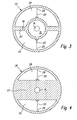
- the cylinder cover 11 is replaced with a relatively wide web 24 by a cylinder cover 32 with a relatively narrow web 33.
- the narrow web 33 engages the cylindrical receptacle 15 tubular.
- the second embodiment is intended to show that the width of the web can be varied to a relatively large extent without undesirably impairing the production of the desired microwave.
- the remaining areas and positions according to FIG. 3 are with them Reference numerals as provided in the first embodiment and not described again.
- the two dielectrics 34, 35 receive a hollow cylindrical section shape.
- the two dielectrics 25, 26 according to FIG. 2 are axially slightly above the web 24 before and also serve as a stop for the piston 13. This is not mandatory.
Landscapes
- Engineering & Computer Science (AREA)
- Radar, Positioning & Navigation (AREA)
- Remote Sensing (AREA)
- Physics & Mathematics (AREA)
- Electromagnetism (AREA)
- Computer Networks & Wireless Communication (AREA)
- General Physics & Mathematics (AREA)
- Health & Medical Sciences (AREA)
- Toxicology (AREA)
- Fluid Mechanics (AREA)
- Mechanical Engineering (AREA)
- General Engineering & Computer Science (AREA)
- Length-Measuring Devices Using Wave Or Particle Radiation (AREA)
- Actuator (AREA)
Claims (10)
- Couvercle d'un cylindre fluidique (10) avec un dispositif de mesure destiné à la saisie de la position de pistons dans le cylindre fluidique (10) et une sonde de couplage à micro-ondes (20) dans le couvercle (11 ; 32 ; 36) du cylindre fluidique (10) pour injecter une onde de guide d'ondes dans l'espace de cylindre (21) contigu et pour éjecter et saisir l'onde de guide d'ondes réfléchie par le piston (13) et avec une électronique d'évaluation (31) destinée à évaluer l'onde de guide d'ondes réfléchie, caractérisé en ce que la sonde de couplage (20) est formée par deux monopôles (28, 29) s'étendant dans des sens radiaux opposés du couvercle (11 ; 32 ; 36), lesquels sont séparés respectivement dans un diélectrique (25, 26 ; 34, 35 ; 38, 39) par une nervure métallique (24 ; 33 ; 37) qui forme un espace creux cylindrique concentrique qui est réalisé comme une conduite d'accès fluidique (16) à l'espace de cylindre (21) et/ou comme un logement (15) pour un organe d'amortissement de position finale (14) cylindrique relié au piston (13).
- Couvercle selon la revendication 1, caractérisé en ce que les diélectriques (25, 26 ; 34, 35 ; 38, 39) sont constitués d'un matériau diélectrique solide et/ou d'un fluide et/ou d'un vide.
- Couvercle selon la revendication 2, caractérisé en ce que les monopôles (28, 29) ne sont pas ou surtout pas disposés pour la génération d'un tracé non homogène du nombre de diélectriques dans un matériau diélectrique solide, et en ce que du matériau diélectrique solide est disposé sur la zone de transition à l'espace de cylindre (21).
- Couvercle selon l'une quelconque des revendications précédentes, caractérisé en ce que les deux diélectriques (25, 26 ; 34, 35 ; 38, 39) possèdent la forme géométrique d'une section de cylindre ou d'une section de cylindre creux et sont disposés de préférence de manière symétrique à la nervure métallique (24 ; 33 ; 37).
- Couvercle selon l'une quelconque des revendications précédentes, caractérisé en ce que les diélectriques (25, 26 ; 34, 35 ; 38, 39) sont disposés dans des évidements (22, 23) ouverts vers l'espace de cylindre (21), formés en conséquence du couvercle de cylindre (11 ; 32 ; 36) métallique.
- Couvercle selon l'une quelconque des revendications précédentes, caractérisé en ce que les deux monopôles (28, 29) sont reliés sur leur base radialement intérieure par des lignes à bande ou conduites coaxiales (30) à l'électronique d'évaluation (31).
- Couvercle selon l'une quelconque des revendications précédentes, caractérisé en ce que l'électronique d'évaluation (31) est disposée sur ou dans le couvercle de cylindre (11) ou en ce que des raccords pour des câbles coaxiaux externes sont prévus sur le couvercle pour la liaison avec une électronique d'évaluation externe.
- Couvercle selon l'une quelconque des revendications précédentes, caractérisé en ce que les monopôles (28, 29) sont alimentés en phase pour la génération d'ondes de mode E01, en particulier avec des amplitudes identiques.
- Couvercle selon la revendication 8, caractérisé en ce que des moyens de commutation à une alimentation en opposition de phase sont prévus pour la génération d'ondes de mode H11, et en ce que l'électronique d'évaluation (31) présente des moyens d'évaluation des deux types d'onde à des fins de détermination de position.
- Couvercle selon l'une quelconque des revendications précédentes, caractérisé en ce que l'électronique d'évaluation (31) contient un générateur de micro-ondes ou est reliée à un tel générateur.
Priority Applications (1)
| Application Number | Priority Date | Filing Date | Title |
|---|---|---|---|
| EP20070011246 EP2000823B1 (fr) | 2007-06-08 | 2007-06-08 | Couvercle d'un cylindre fluidique avec un dispositif de mesure destiné à la saisie de la position de pistons dans le cylindre fluidique doté d'une sonde de couplage à micro-ondes |
Applications Claiming Priority (1)
| Application Number | Priority Date | Filing Date | Title |
|---|---|---|---|
| EP20070011246 EP2000823B1 (fr) | 2007-06-08 | 2007-06-08 | Couvercle d'un cylindre fluidique avec un dispositif de mesure destiné à la saisie de la position de pistons dans le cylindre fluidique doté d'une sonde de couplage à micro-ondes |
Publications (2)
| Publication Number | Publication Date |
|---|---|
| EP2000823A1 EP2000823A1 (fr) | 2008-12-10 |
| EP2000823B1 true EP2000823B1 (fr) | 2012-01-18 |
Family
ID=38651801
Family Applications (1)
| Application Number | Title | Priority Date | Filing Date |
|---|---|---|---|
| EP20070011246 Not-in-force EP2000823B1 (fr) | 2007-06-08 | 2007-06-08 | Couvercle d'un cylindre fluidique avec un dispositif de mesure destiné à la saisie de la position de pistons dans le cylindre fluidique doté d'une sonde de couplage à micro-ondes |
Country Status (1)
| Country | Link |
|---|---|
| EP (1) | EP2000823B1 (fr) |
Families Citing this family (4)
| Publication number | Priority date | Publication date | Assignee | Title |
|---|---|---|---|---|
| DE102008061104A1 (de) * | 2008-12-09 | 2010-06-10 | Festo Ag & Co. Kg | Linearantrieb |
| RU2444748C2 (ru) * | 2010-02-02 | 2012-03-10 | Открытое акционерное общество "Конструкторское бюро по радиоконтролю систем управления, навигации и связи" (ОАО "КБ"Связь") | Способ определения дальности до излучающей обзорной радиолокационной станции |
| NO20120980A1 (no) * | 2012-08-31 | 2014-03-03 | Aker Mh As | Antennesammenstilling for stempelakkumulatorer |
| DE102023210014A1 (de) * | 2023-10-12 | 2025-04-17 | Vega Grieshaber Kg | Arbeitszylinder |
Family Cites Families (2)
| Publication number | Priority date | Publication date | Assignee | Title |
|---|---|---|---|---|
| DE19833220A1 (de) * | 1997-12-15 | 1999-06-17 | Mikrowellen Technologie Und Se | Abstandsmeßvorrichtung und Verfahren zur Bestimmung eines Abstandes |
| DE10205904A1 (de) * | 2002-02-13 | 2003-08-21 | Mikrowellen Technologie Und Se | Abstandsmessvorrichtung und Verfahren zur Bestimmung eines Abstands |
-
2007
- 2007-06-08 EP EP20070011246 patent/EP2000823B1/fr not_active Not-in-force
Also Published As
| Publication number | Publication date |
|---|---|
| EP2000823A1 (fr) | 2008-12-10 |
Similar Documents
| Publication | Publication Date | Title |
|---|---|---|
| EP2116820B1 (fr) | Usage d'un dispositif d'adaptation d'impédance, appareil de mesure avec dispositif d'adaptation d'impédance et procédé pour opérer un guide d'ondes | |
| EP1076380B1 (fr) | Antenne | |
| EP2142810B1 (fr) | Dispositif de mesure de distance, procédé pour déterminer une distance et corps réfléchissant approprié | |
| EP2435804B1 (fr) | Système de mesure de niveau comportant un appareil de mesure de niveau fonctionnant par micro-ondes | |
| EP3563121B1 (fr) | Assemblage de mesure permettant d'analyser les propriétés d'un milieu fluide par des micro-ondes | |
| EP1058341A1 (fr) | Disposition d'un guide d'ondes et d'une antenne | |
| EP0947812A1 (fr) | Capteur du niveau à microondes | |
| EP2687830A2 (fr) | Procédé de surveillance de l'état d'un appareil de mesure du niveau de remplissage fonctionnant selon le principe du radar et appareil de mesure du niveau de remplissage correspondant | |
| EP2000823A1 (fr) | Dispositif de mesure destiné à la saisie de la position de pistons dans un cylindre fluidique doté d'une sonde de couplage à micro-ondes | |
| EP2054633B1 (fr) | Dispositif de mesure de distance, procédé pour déterminer une distance et élément réfléchissant adapté | |
| EP2350572B1 (fr) | Dispositif de mesure de distance et procédé de détermination d'une distance dans une structure de conduite | |
| EP2002282B1 (fr) | Dispositif de mesure de position à micro-ondes et procédé de mesure de position | |
| EP3256824B1 (fr) | Dispositif à deux elements de couplage pour déterminer et surveiller un niveau de remplissage | |
| DE102007009094B4 (de) | Aktor mit Positionsmessvorrichtung | |
| WO2008089804A1 (fr) | Actionneur comportant un élément d'actionneur | |
| WO2016141905A1 (fr) | Capteur de proximite et procédé de mesure de la distance d'une cible | |
| EP2017644B1 (fr) | Procédé et dispositif de mesure destinés à l'enregistrement de la position d'un piston dans un dans un cylindre fluidique à l'aide d'une sonde de couplage à micro-ondes | |
| EP4586396A1 (fr) | Capteur radar et séparateur de guide d'ondes | |
| DE202009001395U1 (de) | Vorrichtung zur Einkopplung von Hochfrequenzsignalen für Frequenzen größer als 1 GHz in einen elektrisch leitenden Hohlleiter | |
| EP2047292B1 (fr) | Procédé et dispositif de mesure de position pour déterminer un objet à mesurer | |
| DE102008061104A1 (de) | Linearantrieb | |
| DE902028C (de) | Breitbandultrahochfrequenzleitung | |
| EP1437588A1 (fr) | Détecteur de champ de dispersion des micro-ondes | |
| EP2187234B1 (fr) | Dispositif de mesure de position de micro-ondes | |
| DE102006052791B3 (de) | Positionsmessvorrichtung mit einer Heizeinrichtung |
Legal Events
| Date | Code | Title | Description |
|---|---|---|---|
| PUAI | Public reference made under article 153(3) epc to a published international application that has entered the european phase |
Free format text: ORIGINAL CODE: 0009012 |
|
| 17P | Request for examination filed |
Effective date: 20071201 |
|
| AK | Designated contracting states |
Kind code of ref document: A1 Designated state(s): AT BE BG CH CY CZ DE DK EE ES FI FR GB GR HU IE IS IT LI LT LU LV MC MT NL PL PT RO SE SI SK TR |
|
| AX | Request for extension of the european patent |
Extension state: AL BA HR MK RS |
|
| AKX | Designation fees paid |
Designated state(s): CH DE FR GB IT LI |
|
| RTI1 | Title (correction) |
Free format text: CYLINDER HEAD WITH A MEASURING DEVICE FOR LOGGING THE PISTON POSITION IN A FLUID CYLINDER USING A MICROWAVE COUPLE SENSOR |
|
| GRAP | Despatch of communication of intention to grant a patent |
Free format text: ORIGINAL CODE: EPIDOSNIGR1 |
|
| GRAS | Grant fee paid |
Free format text: ORIGINAL CODE: EPIDOSNIGR3 |
|
| GRAA | (expected) grant |
Free format text: ORIGINAL CODE: 0009210 |
|
| AK | Designated contracting states |
Kind code of ref document: B1 Designated state(s): CH DE FR GB IT LI |
|
| REG | Reference to a national code |
Ref country code: GB Ref legal event code: FG4D Free format text: NOT ENGLISH |
|
| REG | Reference to a national code |
Ref country code: CH Ref legal event code: NV Representative=s name: TROESCH SCHEIDEGGER WERNER AG Ref country code: CH Ref legal event code: EP |
|
| REG | Reference to a national code |
Ref country code: DE Ref legal event code: R096 Ref document number: 502007009094 Country of ref document: DE Effective date: 20120322 |
|
| PGFP | Annual fee paid to national office [announced via postgrant information from national office to epo] |
Ref country code: FR Payment date: 20120705 Year of fee payment: 6 Ref country code: GB Payment date: 20120516 Year of fee payment: 6 |
|
| PGFP | Annual fee paid to national office [announced via postgrant information from national office to epo] |
Ref country code: IT Payment date: 20120608 Year of fee payment: 6 |
|
| PLBE | No opposition filed within time limit |
Free format text: ORIGINAL CODE: 0009261 |
|
| STAA | Information on the status of an ep patent application or granted ep patent |
Free format text: STATUS: NO OPPOSITION FILED WITHIN TIME LIMIT |
|
| 26N | No opposition filed |
Effective date: 20121019 |
|
| REG | Reference to a national code |
Ref country code: DE Ref legal event code: R097 Ref document number: 502007009094 Country of ref document: DE Effective date: 20121019 |
|
| REG | Reference to a national code |
Ref country code: CH Ref legal event code: PL |
|
| GBPC | Gb: european patent ceased through non-payment of renewal fee |
Effective date: 20130608 |
|
| REG | Reference to a national code |
Ref country code: FR Ref legal event code: ST Effective date: 20140228 |
|
| PG25 | Lapsed in a contracting state [announced via postgrant information from national office to epo] |
Ref country code: GB Free format text: LAPSE BECAUSE OF NON-PAYMENT OF DUE FEES Effective date: 20130608 Ref country code: LI Free format text: LAPSE BECAUSE OF NON-PAYMENT OF DUE FEES Effective date: 20130630 Ref country code: CH Free format text: LAPSE BECAUSE OF NON-PAYMENT OF DUE FEES Effective date: 20130630 |
|
| PG25 | Lapsed in a contracting state [announced via postgrant information from national office to epo] |
Ref country code: IT Free format text: LAPSE BECAUSE OF NON-PAYMENT OF DUE FEES Effective date: 20130608 Ref country code: FR Free format text: LAPSE BECAUSE OF NON-PAYMENT OF DUE FEES Effective date: 20130701 |
|
| PGFP | Annual fee paid to national office [announced via postgrant information from national office to epo] |
Ref country code: DE Payment date: 20150428 Year of fee payment: 9 |
|
| REG | Reference to a national code |
Ref country code: DE Ref legal event code: R119 Ref document number: 502007009094 Country of ref document: DE |
|
| PG25 | Lapsed in a contracting state [announced via postgrant information from national office to epo] |
Ref country code: DE Free format text: LAPSE BECAUSE OF NON-PAYMENT OF DUE FEES Effective date: 20170103 |