EP2054633B1 - Dispositif de mesure de distance, procédé pour déterminer une distance et élément réfléchissant adapté - Google Patents
Dispositif de mesure de distance, procédé pour déterminer une distance et élément réfléchissant adapté Download PDFInfo
- Publication number
- EP2054633B1 EP2054633B1 EP07801711.8A EP07801711A EP2054633B1 EP 2054633 B1 EP2054633 B1 EP 2054633B1 EP 07801711 A EP07801711 A EP 07801711A EP 2054633 B1 EP2054633 B1 EP 2054633B1
- Authority
- EP
- European Patent Office
- Prior art keywords
- measuring device
- distance measuring
- coupling probe
- feeding
- distance
- Prior art date
- Legal status (The legal status is an assumption and is not a legal conclusion. Google has not performed a legal analysis and makes no representation as to the accuracy of the status listed.)
- Ceased
Links
Images




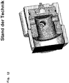
Classifications
-
- F—MECHANICAL ENGINEERING; LIGHTING; HEATING; WEAPONS; BLASTING
- F15—FLUID-PRESSURE ACTUATORS; HYDRAULICS OR PNEUMATICS IN GENERAL
- F15B—SYSTEMS ACTING BY MEANS OF FLUIDS IN GENERAL; FLUID-PRESSURE ACTUATORS, e.g. SERVOMOTORS; DETAILS OF FLUID-PRESSURE SYSTEMS, NOT OTHERWISE PROVIDED FOR
- F15B15/00—Fluid-actuated devices for displacing a member from one position to another; Gearing associated therewith
- F15B15/20—Other details, e.g. assembly with regulating devices
- F15B15/22—Other details, e.g. assembly with regulating devices for accelerating or decelerating the stroke
- F15B15/222—Other details, e.g. assembly with regulating devices for accelerating or decelerating the stroke having a piston with a piston extension or piston recess which throttles the main fluid outlet as the piston approaches its end position
-
- F—MECHANICAL ENGINEERING; LIGHTING; HEATING; WEAPONS; BLASTING
- F15—FLUID-PRESSURE ACTUATORS; HYDRAULICS OR PNEUMATICS IN GENERAL
- F15B—SYSTEMS ACTING BY MEANS OF FLUIDS IN GENERAL; FLUID-PRESSURE ACTUATORS, e.g. SERVOMOTORS; DETAILS OF FLUID-PRESSURE SYSTEMS, NOT OTHERWISE PROVIDED FOR
- F15B15/00—Fluid-actuated devices for displacing a member from one position to another; Gearing associated therewith
- F15B15/20—Other details, e.g. assembly with regulating devices
- F15B15/28—Means for indicating the position, e.g. end of stroke
- F15B15/2815—Position sensing, i.e. means for continuous measurement of position, e.g. LVDT
- F15B15/2869—Position sensing, i.e. means for continuous measurement of position, e.g. LVDT using electromagnetic radiation, e.g. radar or microwaves
-
- G—PHYSICS
- G01—MEASURING; TESTING
- G01B—MEASURING LENGTH, THICKNESS OR SIMILAR LINEAR DIMENSIONS; MEASURING ANGLES; MEASURING AREAS; MEASURING IRREGULARITIES OF SURFACES OR CONTOURS
- G01B15/00—Measuring arrangements characterised by the use of electromagnetic waves or particle radiation, e.g. by the use of microwaves, X-rays, gamma rays or electrons
-
- G—PHYSICS
- G01—MEASURING; TESTING
- G01B—MEASURING LENGTH, THICKNESS OR SIMILAR LINEAR DIMENSIONS; MEASURING ANGLES; MEASURING AREAS; MEASURING IRREGULARITIES OF SURFACES OR CONTOURS
- G01B7/00—Measuring arrangements characterised by the use of electric or magnetic techniques
- G01B7/14—Measuring arrangements characterised by the use of electric or magnetic techniques for measuring distance or clearance between spaced objects or spaced apertures
-
- Y—GENERAL TAGGING OF NEW TECHNOLOGICAL DEVELOPMENTS; GENERAL TAGGING OF CROSS-SECTIONAL TECHNOLOGIES SPANNING OVER SEVERAL SECTIONS OF THE IPC; TECHNICAL SUBJECTS COVERED BY FORMER USPC CROSS-REFERENCE ART COLLECTIONS [XRACs] AND DIGESTS
- Y10—TECHNICAL SUBJECTS COVERED BY FORMER USPC
- Y10T—TECHNICAL SUBJECTS COVERED BY FORMER US CLASSIFICATION
- Y10T29/00—Metal working
- Y10T29/49—Method of mechanical manufacture
- Y10T29/49826—Assembling or joining
Definitions
- the present invention relates to a distance measuring device according to the preamble of claim 1 and a method for determining a distance and a suitable reflection body.
- conventional distance measuring devices are used for example for detecting the piston position of fluidic linear drives and pneumatic and hydraulic cylinders.
- the piston position detection on cylinders can be both discrete, d. H. in discrete places, as well as continuously, d. H. constantly during operation, done.
- a discrete piston position determination is generally required in order to report the execution or termination of a piston movement to a sequential control (eg PLC) in order thus to be able to initiate the next sequence step, for example.
- a sequential control eg PLC
- sensors are predominantly designed as magnetic field-sensitive sensors and are known as reed switches, magnetoresistive (MR), giant magnetoresistive (GMR), Hall switches or magnetic inductive proximity switches.
- MR magnetoresistive
- GMR giant magnetoresistive
- Hall switches magnetic inductive proximity switches.
- the potentiometric for continuous piston position measurement usually measuring systems are used, the potentiometric, according to the LVDT principle (Linear Variable Differential Transformer) magnetrostrictive or operate on the ultrasound principle.
- the piston position is continuously and predominantly output as analog voltage signal in these systems.
- Sensors based on the LVDT principle always require homing when switching on.
- Magnetostrictive sensors are mounted either externally to the cylinder or into a hollow piston rod. Both mounting options mean a significant overhead, are prone to failure or weaken in the case of the hollow piston rod stability of the drive.
- Ultrasonic sensors are only of limited suitability for measuring distance in pneumatic and hydraulic cylinders, since the measuring accuracy changes with the cylinder pressure. In addition to these systems, incremental path measurements are also known.
- the ideal position measuring system for determining the piston position in pneumatic and hydraulic cylinders has the following characteristics: a continuous, absolute displacement measurement with an accuracy of 100 ⁇ m for positioning the piston, complete integration of the sensor with the evaluation electronics in the cylinder cover, switching distances should be externally via an electronic interface adjustable (teach-in capability), a universal sensor, regardless of the cylinder length, measurement results independent of pressure, oil and humidity in the cylinder, and / or reliable measurement results z.
- a microwave sensor for determining the piston position in pneumatic and hydraulic cylinders is in the US4901628 offenart. Another prior art is disclosed in German patent application no. 102 05 904.7 described.
- the measuring arrangement described in the patent application has the following problems in practice for cylinders with a large diameter (> 50 mm): First, the plastic ring for the piston stop and the antenna mount becomes very large. These plastic parts are only up to a diameter of max. 60 mm available as a rod product. Larger diameters require expensive custom-made products. In addition, plastic absorbs water over time or releases water depending on the conditions of use, thereby changing the measuring conditions. The measurement results will then be inaccurate and no longer comply with the specification.
- a piston stop in the plastic lid has the disadvantage that the plastic settles due to frequent impact of the piston and thus changes the physical conditions in the functional space of the lid for the high-frequency sensor. The measurement accuracy also deteriorates.
- a line structure is further provided which has a feed-in block with a feed-in area which connects an HF transceiver to the coupling probe via a waveguide with dielectric holding systems.
- the length of the line structure is measured up to a short circuit (eg piston as reflection body in the case of the pneumatic and hydraulic cylinders), which is also displaceable.
- the distance to be measured takes place here by measuring the phase difference between the transmitted and received signals.
- the RF feed system consists of a coaxial monopole excitation system.
- TEM wave transverse electromagnetic wave
- the monopole system a circular waveguide wave with the characteristic E-field type of the E01 wave. This wave propagates within the barrel in the axial direction. If this wave hits a reflection body (the piston in the pneumatic and hydraulic cylinder), the wave is reflected and converted into the coaxial line system via the excitation section (monopole) and continued.
- the monopole feed consists of a 3-stage coaxial transformation stage (2) with a dielectric holding system (1), preferably of PPS Gf 40 material, for positioning and pressure stabilization.
- the dielectric retention system can only be partially implemented in the form of dielectric supports.
- the Kolbenendanschlag is realized by a base plate with attached collar for the development of a cup-shaped part (3) made of aluminum, which as End piece is mounted on the piston.
- the cup is designed so that the antenna dips contactlessly inside the cup when it stops.
- On the front of the cup a plastic blade (4) is housed to allow a gentle stop.
- This cup also serves as a reflection body for the transmitted electromagnetic wave.
- so-called "corrugations" (5) were realized on the circumference of the reflection body. These are milled grooves that short the electromagnetic wave. Depending on the number of grooves, a nearly perfect short circuit can be realized. In practice, 2 grooves are sufficient.
- the depth of the grooves correspond to a quarter of the wavelength of the used transmission frequency of the electromagnetic wave.
- a further advantageous embodiment of the reflection body is that it can be configured to realize the function of a cushioning. Without end cushioning, the piston would impinge unbraked on the lid. This leads to shocks and can cause damage to the drive system.
- the classic end position damping is realized by the fact that the piston rod protrudes over the piston in the direction of the sensor and is provided with a tapered plastic lance.
- the counterpart in the end cover forms a plastic ring whose inside diameter is just so large that the piston rod with a tapered plastic attachment can dip. If the inner diameter of the plastic ring corresponds to that of the outer diameter of the conical piston rod attachment, then the piston is decelerated.
- the plastic ring In order to allow the cylinder after a deceleration a gentle approach the plastic ring is mounted in the lid so that it can move axially, for example, a few millimeters. If the piston starts again after a deceleration process, it will take the plastic ring with it until it stops. The kinetic energy that the piston then has, it comes to a gentle jerk and the plastic ring separates from the conical plastic attachment of the piston rod. The deceleration process is supported by a screw-adjustable air exchange between the cover and cylinder chamber.
- the disadvantage of the HF position measuring system is that the movement of the plastic ring in the lid space changes the physical conditions for the sensor, thereby considerably impairing the measuring accuracy.
- the calssische Endlagendämpfung can also at realize the proposed configuration.
- the plastic ring sits in the lid and the conical extension of the piston rod is realized on the reflection body.
- the advantage of this solution is that now the movement of the plastic ring is masked by the cup, ie the sensor signals are no longer disturbed by the immersion of the antenna in the cup by the movement of the plastic ring.
- An equally advantageous embodiment is achieved when the operating scheme is reversed.
- the movable plastic ring is now mounted on the outer surface of the cup and the lid immersion surface is tapered and plastic coated.
- the movement of the ring on the reflection body does not affect the electromagnetic wave, since the plastic ring is no longer in the vicinity of the antenna.
- the pneumatic pressure compensation is advantageously realized in the lid.
- the entire pneumatic cylinder between the piston rod and the rear cover is in the presented method z. B. considered as a circular waveguide.
- the transmission frequency of the sensor is selected so that a monomode propagation of the electromagnetic wave (in the example in E01 mode) is possible.
- the excitation of waveguide modes of lower order is prevented by the geometry of the feed.
- the transmission signal In order to measure the distance between piston and sensor continuously, the transmission signal must be modulated. This can be done in the form of a frequency modulation or by evaluating the phase difference between the transmitted and received signal at several frequencies.
- the transmission frequency is usually between 100 MHz and 25 GHz.
- a dielectric secondary ring serves as a stop protection of the moving reflection body and was taken into account in the electromagnetic design of the feed system. It has proved to be particularly advantageous if the line structure is a circular waveguide, preferably a cylinder with a piston, as a reflection body. Such a circular waveguide may for example be a pneumatic cylinder or a hydraulic cylinder. The existing disadvantages are thus eliminated in particular for these applications. Due to the presence of holes in the feed block, in which the holding system, the coupling probe and the coaxial feed region can be introduced, a simple assembly is ensured and the entire distance measuring device can be integrated almost anywhere in existing line structures.
- the coupling probe is designed as a monopole excitation system and the feed of the electromagnetic wave takes place coaxially, so that a circular waveguide wave can be fed, and converted to the monopole via a multi-stage coaxial transformation stage.
- a multi-stage coaxial transformation stage which may have a flat surface, on the center of which an electrically conductive cylinder is provided, and to which an electrically conductive pin connects as an inner conductor of the coaxial feed, it is achieved that the entire feed takes place in a simple manner.
- the holding system consists of dielectric, z. B. Lexan, and serves to position the coupling probe in the cylinder.
- the feed-in block can be realized particularly cost-effectively by the monopole excitation system is inserted into the cylinder cover and the dielectric holding system by means of plastic injection method that connects firmly with the cylinder cover.
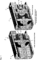
- Fig. 1 the distance measuring device according to the application is shown with line structure 1 and feed block with feed 2, wherein the Feed region comprises a coupling probe 3 via a dielectric support system 5 with the waveguide 7.
- the dielectric secondary ring 9 is shown, on the one hand serves as a mechanical security stop and is designed as a secondary fitting and Abstrahlsystem.
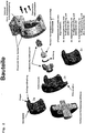
- the respective components of the distance measuring device according to the application in the Fig. 2 represented, wherein the essential components, such as feed block with a feed region 2, are shown in an exploded view.
- the dielectric holding system holds the coupling probe 3, designed as a monopole excitation system, which contains a pin that can be accommodated in a coaxial waveguide.
- the secondary dielectric ring 9 is shown.
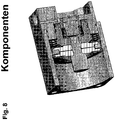
- the reflection body is shown with attached collar to form a cup-shaped element, the base plate advantageously has a groove structure.
- the infeed system consists of a coaxial monopole excitation system.
- a transversal electromagnetic wave ie TEM wave
- the monopole system excites a circular waveguide wave with the characteristic E-field type of the E01 wave. This wave propagates within the barrel in the axial direction. If this wave hits a reflection body, ie the piston in the pneumatic and hydraulic cylinder, the wave is reflected and converted via the excitation section (monopole) into the coaxial line system and forwarded to an HF transceiver (transmitting and receiving unit).
- the monopole feed consists of a multi-stage coaxial transformation stage as a coupling probe 3 with a dielectric holding system 5, preferably of PPS Gf 40 material, for positioning and pressure stabilization.
- a dielectric holding system 5 preferably of PPS Gf 40 material
- the dielectric retention system can only be carried out partially in the form of dielectric supports.
- the Kolbenendanschlag is through a cup-shaped part 6 z. B. made of aluminum, which is mounted as an end on the piston.
- the cup is designed so that the antenna dips contactlessly inside the cup when it stops.
- On the front side of the cup a plastic blade 7 is housed to allow a gentle stop. This cup also serves as a reflection body for the transmitted electromagnetic wave.
- corregations 8 have been realized on the circumference of the reflection body. These are milled grooves that short the electromagnetic wave. Depending on the number of grooves, a nearly perfect short circuit can be realized. In practice, 2 grooves are sufficient. The depth of the grooves correspond to approximately one quarter of the wavelength of the electromagnetic wave transmission frequency used when there is air in the grooves. The depth of the grooves can be significantly shortened if this z. B. Teflon filled. In practice, one will insert dielectric rings.
- a further advantageous embodiment of the reflection body is that it can be designed so that it can realize the function of a cushioning. Without end cushioning, the piston would impinge unbraked on the lid.
- the classic end position damping is realized by the fact that the piston rod protrudes over the piston in the direction of the sensor and is provided with a tapered plastic lance.
- the counterpart in the end cover forms a plastic ring whose inside diameter is just so large that the piston rod with a tapered plastic attachment can dip. If the inner diameter of the plastic ring corresponds to that of the outer diameter of the conical piston rod attachment, then the piston is decelerated. In order to allow the cylinder after a deceleration a gentle approach, the plastic ring is stored in the lid so that it z. B. can move a few millimeters axially.
- the piston starts again after a deceleration process, it will take the plastic ring with it until it stops.
- Supported is the Braking process by means of a screw adjustable air exchange between the lid and cylinder chamber.
- the disadvantage of the HF position measuring system is that the movement of the plastic ring in the lid space changes the physical conditions for the sensor, thereby considerably impairing the measuring accuracy.
- the classic end position damping can also be realized in the proposed configuration.
- the plastic ring sits in the lid and the conical extension of the piston rod is realized on the reflection body.
- the entire pneumatic cylinder between the piston rod and rear cover z. B. considered as a circular waveguide.
- the transmission frequency of the sensor is selected so that a monomodal propagation of the electromagnetic wave (in the example in E01 mode) is possible and that the excitation of waveguide wave modes of higher order is prevented.
- the excitation of waveguide modes of lower order is prevented by the geometry of the feed.
- the excitation of the electromagnetic wave in the cylinder takes place for example via a monopole in the manner presented.
- the transmission signal In order to measure the distance between piston and coupling probe continuously, the transmission signal must be modulated. This can be done in the form of a frequency modulation. However, to achieve a high range resolution, a large frequency sweep is required. In practice, more advantageous is the emission of a CW signal, z. B. at three different frequencies (Example: 5.8 GHz, 6.0 GHz, 6.2 GHz) to determine a clear distance range, each with subsequent evaluation of the phase difference between transmit and receive signal as a highly accurate reading for the distance between the probe and the piston.
- the number of frequencies to be used as well as their position depends primarily on the maximum distance to be measured as well as on the necessary fault tolerance with respect to the phase angle measurement. In general, with a small frequency difference between two measurement frequencies, the maximum measurable distance is greater, but the distinction between two consecutive periods requires a higher accuracy of the phase angle measurement than with a larger frequency difference.
- the interference immunity is therefore higher for larger differences between the individual measurement frequencies.
- the position accuracy is essentially determined by the accuracy of the phase angle measurement at the highest measurement frequency, because there the wavelength is smallest.
- path change Phase angle change ⁇ wavelength / 180 °
- Microwave piston position measurement is based on the following principle: An electromagnetic wave of suitable frequency is coupled into the cylinder.
- the cylinder itself acts as a conduit structure for the shaft.
- the shaft runs in the cylinder to the piston as a reflection body.
- the electromagnetic wave is largely reflected because the piston behaves electrically similar to a short circuit.
- the reflected wave returns the cylinder and is decoupled from the cylinder via the same structure over which the coupling was made.
- the phase angle between the injected and the reflected signal is measured. If the piston changes its position, the distance covered by the electromagnetic wave in the cylinder changes. Due to the change in the track, there is a change in the signal propagation time and thus also in a different phase angle between the traveling and the reflected wave.
- phase between the signal going back and forth can be used as a measure of the piston position.
- ⁇ 2 x ⁇ 360 ° ⁇ + ⁇ 0 ⁇ 0 is a phase offset, which is mainly determined by the supply line and the coupling. It is constant and therefore has no influence on the actual position measurement. From the above equation also results in the necessary phase measurement accuracy to achieve a predetermined position measurement accuracy can.
- the phase angle of the reflected signal can not be measured directly and thus the voltage measured at a mixer output is not directly measured proportional to the piston position, a suitable algorithm is needed for the position search. Since the output signal repeats periodically, it must above all be ensured that the position search is unambiguous, ie it must be possible to determine unambiguously in which period the piston is located.
- One way of determining the position would be to take many readings during a frequency sweep. These measured values are then transformed into the frequency domain by means of an FFT or DFT. From the position of the maximum of the resulting spectrum, the position of the piston can then be determined. As long as one does not allow subsampling when taking the readings, no ambiguity problems can occur with this method. Also obtained by this method already without the inclusion of a position table values for the piston positions. The disadvantage is the fact that on the one hand, a relatively large number of measuring points must be recorded and that the computational complexity is relatively large.
- Another possibility is to measure only at a few frequencies and to determine the piston position using position tables.
- the measured values are simply compared with the values of the points in the position table.
- the determined position corresponds to the table value, which is most similar to the measured values.
- a disadvantage of this method is that it can possibly lead to ambiguities. Since direct phase measurement is not performed, uniqueness can not be ensured by complying with the condition outlined above. More detailed investigations show that when only two measuring frequencies are used, there are always points with identical measured values if the cylinder is longer than ⁇ / 2. Since this is usually the case in practice, at least three frequencies should be used. If the three measuring frequencies are selected cleverly, there are then no positions where all three measured values are identical.
- the measured values at two piston positions must differ by a minimum amount in order to be able to ensure unambiguity even with certain measuring errors. Therefore, the use of more than three frequencies can be advantageous, especially for larger cylinder lengths. In addition, this also the measurement accuracy increased, since noise or measurement errors that occur only at one frequency are suppressed.
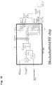
- the transceiver signals are generated in a corresponding RF electronics.
- the circuit board which carries the RF electronics connected.
- the HF electronics are designed as a single-chip substrate, for example in silicon germanium.
- the oscillator is stabilized in frequency via a control loop.
- the oscillator output signal is divided in frequency, z. B. corrected by a factor of 16 and a PLL quartz accurate.
- the transmission branch is then a switchable divider, which determines the final transmission frequency on the divider ratio. So this can be at an oscillator frequency of 24 GHz at 12, 6, 3, ... GHz.
- the frequency-related power amplifier is activated by external wiring.
- the signal is emitted via the monopole antenna.
- the electromagnetic wave After the electromagnetic wave has been reflected on the reflection body, it is received via the monopole antenna and forwarded to the receiver via two directional couplers.
- the receiver is implemented as an IQ receiver.
- the intermediate frequencies of the receiver (IF out) are converted to analog / digital and evaluated in an FPGA (free programmable gate array). The result is the distance between sensor and piston.
- the function blocks DSP (digital signal processor), parts of the interface, memory and parts of the PLL control are implemented in the FPGA.
Landscapes
- Physics & Mathematics (AREA)
- Engineering & Computer Science (AREA)
- Fluid Mechanics (AREA)
- Mechanical Engineering (AREA)
- General Engineering & Computer Science (AREA)
- Electromagnetism (AREA)
- General Physics & Mathematics (AREA)
- Health & Medical Sciences (AREA)
- Radar, Positioning & Navigation (AREA)
- Remote Sensing (AREA)
- Toxicology (AREA)
- Length-Measuring Devices Using Wave Or Particle Radiation (AREA)
- Actuator (AREA)
- Measurement Of Length, Angles, Or The Like Using Electric Or Magnetic Means (AREA)
- Radar Systems Or Details Thereof (AREA)
Claims (34)
- Dispositif de mesure de distance comportant une électronique d'évaluation et un dispositif capteur qui comporte au moins une sonde de couplage pour l'injection d'un signal d'émission dans une structure de guidage pourvue d'un corps réfléchissant, dans lequel la mesure de la distance entre le point d'injection défini par la sonde de couplage et le corps réfléchissant est effectuée, dans lequel le corps réfléchissant présente une plaque de base à collet rapporté pour former un élément en forme de godet, dans lequel le collet rapporté comprend la sonde de couplage à une position d'extrémité du corps réfléchissant, caractérisé en ce que le collet rapporté est pourvu d'une lamelle en matière plastique.
- Dispositif de mesure de distance selon la revendication 1, dans lequel une face frontale présentant une structure rainurée est prévue dans la plaque de base.
- Dispositif de mesure de distance selon l'une des revendications 1 ou 2, dans lequel la plaque de base comporte une face frontale présentant une structure rainurée s'étendant dans la direction circonférentielle.
- Dispositif de mesure de distance selon la revendication 3, dans lequel la structure rainurée présente au moins deux rainures, de préférence 3 rainures ou plus.
- Dispositif de mesure de distance selon la revendication 4, dans lequel les rainures sont remplies d'un matériau diélectrique.
- Dispositif de mesure de distance selon l'une des revendications 1 à 5, dans lequel il est prévu un élément annulaire, de préférence un anneau en matière plastique, comprenant le collet en position d'extrémité pour assurer un amortissement de fin de course.
- Dispositif de mesure de distance selon l'une des revendications 1 à 5, dans lequel il est prévu un élément annulaire, de préférence un anneau en matière plastique, qui est prévu sur la surface extérieure du collet et qui présente une paire de surfaces correspondant à la surface extérieure du collet, qui s'étendent de préférence de manière conique, pour assurer un amortissement de fin de course.
- Dispositif de mesure de distance selon l'une des revendications 1 à 7, dans lequel la structure de guidage présente un bloc d'injection comportant une zone d'injection reliant un émetteur-récepteur HF à la sonde de couplage par l'intermédiaire d'un guide d'ondes pourvu d'un système de support diélectrique.
- Dispositif de mesure de distance selon la revendication 8, dans lequel le système de support diélectrique est constitué d'un matériau à faible absorption ou à faible libération d'eau et peut être réalisé à la fois sous forme solide et dans des supports individuels pour des cylindres de grand diamètre.
- Dispositif de mesure de distance selon l'une des revendications 1 à 9, dans lequel la structure de guidage est un guide d'ondes circulaire, de préférence un cylindre comportant un piston en tant que corps réfléchissant.
- Dispositif de mesure de distance selon la revendication 10, dans lequel le corps réfléchissant est placé sur le piston.
- Dispositif de mesure de distance selon l'une des revendications 1 à 11, dans lequel il est prévu une compensation de pression pneumatique.
- Dispositif de mesure de distance selon l'une des revendications 8 à 12, dans lequel le bloc d'injection comporte des alésages dans lesquels peuvent être introduits le système de support, la sonde de couplage et la zone d'injection coaxiale.
- Dispositif de mesure de distance selon l'une des revendications 1 à 13, dans lequel la sonde de couplage est configurée sous la forme d'un système d'excitation à monopôle, et dans lequel l'injection de l'onde électromagnétique est effectuée coaxialement et est convertie en monopôle par l'intermédiaire d'un étage de transformation coaxial à plusieurs étages.
- Dispositif de mesure de distance selon l'une des revendications 1 à 14, dans lequel la sonde de couplage est réalisée sous la forme d'un module de transformation à trois étages comportant une surface de base plane sur laquelle est prévu de manière centrale un cylindre auquel est reliée une broche, par l'intermédiaire de laquelle la zone d'injection est reliée à la sonde de couplage.
- Dispositif de mesure de distance selon la revendication 15, dans lequel la sonde de couplage est revêtue d'une matière plastique, de préférence d'une matière plastique à faible absorption d'eau et à faible libération d'eau, par exemple du PPS Gf 40.
- Dispositif de mesure de distance selon l'une des revendications 1 à 16, dans lequel le signal d'émission est injecté par l'intermédiaire de la sonde de couplage sous la forme d'une onde électromagnétique dans la plage des hautes fréquences.
- Dispositif de mesure de distance selon la revendication 17, dans lequel l'onde électromagnétique est injectée dans la plage des hautes fréquences comprise entre 100 MHz et 25 GHz.
- Dispositif de mesure de distance selon l'une des revendications 1 à 18, dans lequel au moins deux signaux d'émission sont émis par la sonde de couplage sous la forme d'ondes électromagnétiques présentant des fréquences différentes.
- Dispositif de mesure de distance selon l'une des revendications 18 ou 19, dans lequel l'onde électromagnétique couplée en entrée présente un mode de propagation monomode, de préférence un mode TEM pour une structure coaxiale.
- Dispositif de mesure de distance selon l'une des revendications 17 à 20, dans lequel l'onde électromagnétique couplée en entrée présente un mode de propagation monomode, de préférence un mode E01 pour un guide d'ondes circulaire.
- Dispositif de mesure de distance selon l'une des revendications 1 à 21, dans lequel le dispositif capteur comprend une électronique haute fréquence comportant une branche d'émission et une branche de réception.
- Dispositif de mesure de distance selon l'une des revendications 1 à 22, dans lequel l'électronique d'évaluation et/ou le dispositif capteur sont prévus, de préférence en tant qu'électronique d'interface, dans un système à puce qui est de préférence prévu sur le bloc d'alimentation.
- Dispositif de mesure de distance selon l'une des revendications 22 ou 23, dans lequel l'électronique haute fréquence, constituée de PLL, d'oscillateurs (VCO), de mélangeurs, de répartiteurs de fréquence et d'amplificateurs, est intégrée sur un substrat commun (solution à puce unique).
- Dispositif de mesure de distance selon la revendication 24, dans lequel le matériau du substrat est le silicium-germanium, le silicium, le carbure de silicium-germanium ou le carbure de silicium.
- Dispositif de mesure de distance selon les revendications 22 à 25, caractérisé en ce que la fréquence d'émission et de réception du dispositif à puce peut être sélectionnée en réglant le rapport de division, par exemple en appliquant une tension externe, par pas discrets, de préférence par pas de 2.
- Dispositif de mesure de distance selon l'une des revendications 1 à 26, dans lequel l'électronique d'évaluation constituée de DSP, de PLL, de mémoires, est réalisée sous la forme d'un FPGA (réseau de portes librement programmable).
- Dispositif de mesure de distance selon la revendication 27, dans lequel l'électronique d'évaluation est réalisée sous la forme d'une électronique d'interface à la fois analogique, par exemple de 0 à 20 mA, de 0 à 10V, et numérique, par exemple sous la forme d'un bus CAN, et dans lequel des parties du FPGA sont utilisées pour générer le protocole d'interface ou pour commander la conversion numérique/analogique.
- Procédé de détermination d'une distance à l'aide d'un dispositif de mesure de distance selon l'une des revendications 1 à 28, comprenant les étapes consistant à :a. prévoir une structure de guidage comportant un corps réfléchissant comprenant un bloc d'injection ayant une région d'injection reliant un émetteur-récepteur HF à une sonde de couplage par l'intermédiaire d'un guide d'ondes pourvu d'un système de support diélectrique, et le corps réfléchissant comportant une plaque de base à collet rapporté pour former un élément en forme de godet qui peut être monté comme pièce d'extrémité sur le corps réfléchissant, et le collet rapporté comprenant la sonde de couplage à une position d'extrémité du corps réfléchissant, et le collet rapporté étant pourvu d'une lamelle en matière plastique,b. mesurer la distance entre le point d'injection défini par la sonde de couplage et le corps réfléchissant, dans lequel au moins deux signaux d'émission sont couplés en entrée, de préférence émises et reçues, sous la forme d'ondes électromagnétiques présentant des fréquences différentes par l'intermédiaire de la sonde de couplage.
- Procédé selon la revendication 29, dans lequel la distance est mesurée par une évaluation respective de la différence de phase entre le signal émis et le signal reçu de l'onde électromagnétique.
- Procédé selon l'une des revendications 29 ou 30, dans lequel la différence est faible à au moins deux fréquences d'émission de l'onde électromagnétique respective, et est de préférence égale à 1% de la valeur absolue, afin de couvrir une large plage de mesure.
- Procédé selon l'une des revendications 29 ou 30, dans lequel la différence entre les fréquences du signal d'émission de l'onde électromagnétique respective est élevée, de préférence 20 de la valeur absolue, afin d'obtenir une immunité élevée aux brouillages.
- Procédé selon l'une des revendications 29 à 32, dans lequel les signaux d'émission sont émis en continu.
- Procédé selon l'une des revendications 29 à 32, dans lequel trois signaux d'émission sont émis sous la forme d'ondes électromagnétiques par l'intermédiaire de la sonde de couplage.
Applications Claiming Priority (2)
| Application Number | Priority Date | Filing Date | Title |
|---|---|---|---|
| DE102006038469A DE102006038469A1 (de) | 2006-08-17 | 2006-08-17 | Abstandsmessvorrichtung und Verfahren zur Bestimmung eines Abstands und ein geeigneter Reflexionskörper |
| PCT/EP2007/007258 WO2008019862A2 (fr) | 2006-08-17 | 2007-08-16 | Dispositif de mesure de distance, procédé pour déterminer une distance et élément réfléchissant adapté |
Publications (2)
| Publication Number | Publication Date |
|---|---|
| EP2054633A2 EP2054633A2 (fr) | 2009-05-06 |
| EP2054633B1 true EP2054633B1 (fr) | 2018-08-01 |
Family
ID=38567051
Family Applications (1)
| Application Number | Title | Priority Date | Filing Date |
|---|---|---|---|
| EP07801711.8A Ceased EP2054633B1 (fr) | 2006-08-17 | 2007-08-16 | Dispositif de mesure de distance, procédé pour déterminer une distance et élément réfléchissant adapté |
Country Status (5)
| Country | Link |
|---|---|
| US (2) | US8220320B2 (fr) |
| EP (1) | EP2054633B1 (fr) |
| JP (2) | JP5453091B2 (fr) |
| DE (1) | DE102006038469A1 (fr) |
| WO (1) | WO2008019862A2 (fr) |
Families Citing this family (8)
| Publication number | Priority date | Publication date | Assignee | Title |
|---|---|---|---|---|
| DE102006038469A1 (de) * | 2006-08-17 | 2008-02-28 | Astyx Gmbh | Abstandsmessvorrichtung und Verfahren zur Bestimmung eines Abstands und ein geeigneter Reflexionskörper |
| DE102007020046A1 (de) | 2007-04-27 | 2008-10-30 | Astyx Gmbh | Abstandsmessvorrichtung und Verfahren zur Bestimmung eines Abstands und ein geeigneter Reflexionskörper |
| US8362788B2 (en) | 2007-08-16 | 2013-01-29 | Astyx Gmbh | Double piston rod |
| DE102008061227A1 (de) | 2008-11-14 | 2010-07-15 | Astyx Gmbh | Abstandsmessvorrichtung und Verfahren zur Ermittlung eines Abstands in einer Leitungsstruktur |
| US8531191B2 (en) * | 2010-11-22 | 2013-09-10 | General Electric Company | Sensor assembly and methods of measuring a proximity of a machine component to a sensor |
| US20120126794A1 (en) * | 2010-11-22 | 2012-05-24 | Raymond Jensen | Sensor Assembly And Methods Of Assembling A Sensor Probe |
| CN105337013B (zh) * | 2015-11-13 | 2018-07-17 | 太原理工大学 | 一种基于零折射率材料的波导功率分配器 |
| CN109891216A (zh) * | 2016-04-12 | 2019-06-14 | 镜元科技股份有限公司 | 大光圈太赫兹-吉赫兹镜片系统 |
Citations (3)
| Publication number | Priority date | Publication date | Assignee | Title |
|---|---|---|---|---|
| US4901628A (en) * | 1983-08-11 | 1990-02-20 | General Motors Corporation | Hydraulic actuator having a microwave antenna |
| JPH1086945A (ja) * | 1996-09-12 | 1998-04-07 | Asahi Sakai Kk | 軽量容器の安定具 |
| WO2003069269A2 (fr) * | 2002-02-13 | 2003-08-21 | Mikrowellen-Technologie Und Sensoren Gmbh | Systeme de mesure de distance et procede pour determiner une distance |
Family Cites Families (26)
| Publication number | Priority date | Publication date | Assignee | Title |
|---|---|---|---|---|
| US3341062A (en) * | 1965-02-01 | 1967-09-12 | Robert E Phillips | Non-spill drinking cup |
| US3820386A (en) * | 1972-05-12 | 1974-06-28 | Scans Associates Inc | Method and apparatus for determining top dead center in internal combustion engines |
| JPS5693504U (fr) * | 1979-12-21 | 1981-07-25 | ||
| EP0104172B1 (fr) * | 1982-03-30 | 1987-07-15 | REUTER, Martin | Installation pour determiner une distance relative dans un dispositif a cylindre et piston |
| JPS6065902A (ja) * | 1983-09-21 | 1985-04-15 | Toshiba Mach Co Ltd | 油圧シリンダの減速機構 |
| US5036892A (en) * | 1984-07-10 | 1991-08-06 | The Coca-Cola Company | Automatic control system for filling beverage containers |
| US4733414A (en) * | 1986-10-02 | 1988-03-29 | Wilkes Karl A | Spring loaded drain cleaning device |
| JP2583723B2 (ja) * | 1991-04-18 | 1997-02-19 | エンドレス ウント ハウザー ゲゼルシヤフト ミツト ベシユレンクテル ハフツング ウント コンパニー | 反射ビーム方式による間隔距離測定のための方法及び装置 |
| JPH061879U (ja) * | 1992-06-11 | 1994-01-14 | カヤバ工業株式会社 | 油圧緩衝器 |
| USH1555H (en) * | 1993-11-08 | 1996-07-02 | Chrysler Corporation | Piston top dead center locating tool |
| US5744705A (en) * | 1995-08-07 | 1998-04-28 | Chevron U.S.A. Inc. | Method and apparatus for engine testing |
| DE19648112C1 (de) * | 1996-11-21 | 1998-03-05 | Contitech Luftfedersyst Gmbh | Einrichtung zur berührungslosen Abstandsmessung |
| US6416829B2 (en) * | 1997-06-06 | 2002-07-09 | Fort James Corporation | Heat insulating paper cups |
| TW445235B (en) * | 1998-08-07 | 2001-07-11 | Toyoda Automatic Loom Works | Position detector for fluid cylinder |
| JP2000130408A (ja) * | 1998-10-30 | 2000-05-12 | Ckd Corp | 流体圧シリンダ |
| DE19859202A1 (de) * | 1998-12-21 | 2000-07-13 | Trw Automotive Electron & Comp | Vorrichtung zur Abstandsmessung |
| DE10051825A1 (de) * | 2000-10-19 | 2002-04-25 | Contitech Luftfedersyst Gmbh | Kraftfahrzeug-Luftfedersystem mit Ultraschall-Messanordnung |
| US6993967B2 (en) * | 2002-07-12 | 2006-02-07 | Ti Group Automotive Systems, L.L.C. | Fluid level sensor |
| US6978676B2 (en) * | 2002-09-27 | 2005-12-27 | James F. Munro | Distance measuring systems and methods thereof |
| US7023199B2 (en) * | 2002-12-31 | 2006-04-04 | Caterpillar Inc. | Position sensing cylinder cap for ease of service and assembly |
| US20060243227A1 (en) * | 2005-04-28 | 2006-11-02 | Greve Christopher G | Variable-compression engine |
| US7511800B2 (en) * | 2005-11-28 | 2009-03-31 | Robert Bosch Company Limited | Distance measurement device with short range optics |
| DE102006038469A1 (de) * | 2006-08-17 | 2008-02-28 | Astyx Gmbh | Abstandsmessvorrichtung und Verfahren zur Bestimmung eines Abstands und ein geeigneter Reflexionskörper |
| US8109097B2 (en) * | 2007-03-07 | 2012-02-07 | Thermal Power Recovery, Llc | High efficiency dual cycle internal combustion engine with steam power recovered from waste heat |
| DE102007020046A1 (de) * | 2007-04-27 | 2008-10-30 | Astyx Gmbh | Abstandsmessvorrichtung und Verfahren zur Bestimmung eines Abstands und ein geeigneter Reflexionskörper |
| US8362788B2 (en) * | 2007-08-16 | 2013-01-29 | Astyx Gmbh | Double piston rod |
-
2006
- 2006-08-17 DE DE102006038469A patent/DE102006038469A1/de not_active Withdrawn
-
2007
- 2007-08-16 US US12/377,666 patent/US8220320B2/en not_active Expired - Fee Related
- 2007-08-16 JP JP2009524132A patent/JP5453091B2/ja not_active Expired - Fee Related
- 2007-08-16 EP EP07801711.8A patent/EP2054633B1/fr not_active Ceased
- 2007-08-16 WO PCT/EP2007/007258 patent/WO2008019862A2/fr not_active Ceased
-
2012
- 2012-07-16 US US13/550,168 patent/US9371847B2/en not_active Expired - Fee Related
-
2014
- 2014-01-06 JP JP2014000439A patent/JP5899248B2/ja not_active Expired - Fee Related
Patent Citations (3)
| Publication number | Priority date | Publication date | Assignee | Title |
|---|---|---|---|---|
| US4901628A (en) * | 1983-08-11 | 1990-02-20 | General Motors Corporation | Hydraulic actuator having a microwave antenna |
| JPH1086945A (ja) * | 1996-09-12 | 1998-04-07 | Asahi Sakai Kk | 軽量容器の安定具 |
| WO2003069269A2 (fr) * | 2002-02-13 | 2003-08-21 | Mikrowellen-Technologie Und Sensoren Gmbh | Systeme de mesure de distance et procede pour determiner une distance |
Non-Patent Citations (1)
| Title |
|---|
| ANONYMOUS: "Microwave piston position detection", RESEARCH DISCLOSURE, MASON PUBLICATIONS, HAMPSHIRE, GB, vol. 279, no. 24, 1 July 1987 (1987-07-01), XP007111721, ISSN: 0374-4353 * |
Also Published As
| Publication number | Publication date |
|---|---|
| DE102006038469A1 (de) | 2008-02-28 |
| US20130015997A1 (en) | 2013-01-17 |
| JP5453091B2 (ja) | 2014-03-26 |
| EP2054633A2 (fr) | 2009-05-06 |
| JP2014074722A (ja) | 2014-04-24 |
| US9371847B2 (en) | 2016-06-21 |
| US8220320B2 (en) | 2012-07-17 |
| WO2008019862A2 (fr) | 2008-02-21 |
| JP5899248B2 (ja) | 2016-04-06 |
| US20100223983A1 (en) | 2010-09-09 |
| JP2010501070A (ja) | 2010-01-14 |
Similar Documents
| Publication | Publication Date | Title |
|---|---|---|
| EP2142810B1 (fr) | Dispositif de mesure de distance, procédé pour déterminer une distance et corps réfléchissant approprié | |
| EP1474651B1 (fr) | Systeme de mesure de distance et procede pour determiner une distance | |
| EP2054633B1 (fr) | Dispositif de mesure de distance, procédé pour déterminer une distance et élément réfléchissant adapté | |
| EP1040316B1 (fr) | Dispositif de mesure de distance et procede pour determiner une distance | |
| DE19833220A1 (de) | Abstandsmeßvorrichtung und Verfahren zur Bestimmung eines Abstandes | |
| EP3069162B1 (fr) | Dispositif de mesure permettant de déterminer une distance dans une structure conductrice | |
| EP2350572B1 (fr) | Dispositif de mesure de distance et procédé de détermination d'une distance dans une structure de conduite | |
| WO2015000452A1 (fr) | Capteur de proximité et procédé pour mesurer la distance d'un objet | |
| DE19903183A1 (de) | Hochfrequenz-Abstandsmeßeinrichtung | |
| DE112015006258B4 (de) | Näherungssensor und Verfahren zur Messung des Abstands eines Targets | |
| WO2006058726A1 (fr) | Dispositif de mesure de distances et procede pour determiner une distance | |
| EP2006549B1 (fr) | Dispositif de mesure destiné à la mesure d'au moins un paramètre dans un cylindre fluidique à l'aide de micro-ondes | |
| EP3658861B1 (fr) | Capteur d'angle doté du guide d'ondes creux annulaire en tant qu'échelle | |
| DE102006021206A1 (de) | Mikrowellen-Positionsmessvorrichtung und Positionsmessverfahren | |
| EP2017644B1 (fr) | Procédé et dispositif de mesure destinés à l'enregistrement de la position d'un piston dans un dans un cylindre fluidique à l'aide d'une sonde de couplage à micro-ondes | |
| WO2007128369A1 (fr) | Dispositif de mesure de position hyperfréquence et procédé de mesure de position | |
| DE102012202072A1 (de) | Messvorrichtung, Hohlkörper und Verfahren | |
| DE202015101681U1 (de) | Positionsmesssystem | |
| EP3076030A1 (fr) | Système de mesure de position | |
| DE202013012904U1 (de) | Näherungssensor |
Legal Events
| Date | Code | Title | Description |
|---|---|---|---|
| PUAI | Public reference made under article 153(3) epc to a published international application that has entered the european phase |
Free format text: ORIGINAL CODE: 0009012 |
|
| 17P | Request for examination filed |
Effective date: 20090315 |
|
| AK | Designated contracting states |
Kind code of ref document: A2 Designated state(s): AT BE BG CH CY CZ DE DK EE ES FI FR GB GR HU IE IS IT LI LT LU LV MC MT NL PL PT RO SE SI SK TR |
|
| AX | Request for extension of the european patent |
Extension state: AL BA HR MK RS |
|
| DAX | Request for extension of the european patent (deleted) | ||
| R17D | Deferred search report published (corrected) |
Effective date: 20080221 |
|
| 17Q | First examination report despatched |
Effective date: 20110117 |
|
| RBV | Designated contracting states (corrected) |
Designated state(s): DE FR GB SE |
|
| APBK | Appeal reference recorded |
Free format text: ORIGINAL CODE: EPIDOSNREFNE |
|
| APBN | Date of receipt of notice of appeal recorded |
Free format text: ORIGINAL CODE: EPIDOSNNOA2E |
|
| APBR | Date of receipt of statement of grounds of appeal recorded |
Free format text: ORIGINAL CODE: EPIDOSNNOA3E |
|
| APAF | Appeal reference modified |
Free format text: ORIGINAL CODE: EPIDOSCREFNE |
|
| APAF | Appeal reference modified |
Free format text: ORIGINAL CODE: EPIDOSCREFNE |
|
| APBX | Invitation to file observations in appeal sent |
Free format text: ORIGINAL CODE: EPIDOSNOBA2E |
|
| APAQ | Information on invitation to file observation in appeal modified |
Free format text: ORIGINAL CODE: EPIDOSCOBA2E |
|
| APBZ | Receipt of observations in appeal recorded |
Free format text: ORIGINAL CODE: EPIDOSNOBA4E |
|
| APBT | Appeal procedure closed |
Free format text: ORIGINAL CODE: EPIDOSNNOA9E |
|
| GRAP | Despatch of communication of intention to grant a patent |
Free format text: ORIGINAL CODE: EPIDOSNIGR1 |
|
| INTG | Intention to grant announced |
Effective date: 20180316 |
|
| GRAS | Grant fee paid |
Free format text: ORIGINAL CODE: EPIDOSNIGR3 |
|
| GRAA | (expected) grant |
Free format text: ORIGINAL CODE: 0009210 |
|
| AK | Designated contracting states |
Kind code of ref document: B1 Designated state(s): DE FR GB SE |
|
| REG | Reference to a national code |
Ref country code: GB Ref legal event code: FG4D Free format text: NOT ENGLISH |
|
| REG | Reference to a national code |
Ref country code: DE Ref legal event code: R096 Ref document number: 502007016315 Country of ref document: DE |
|
| PG25 | Lapsed in a contracting state [announced via postgrant information from national office to epo] |
Ref country code: SE Free format text: LAPSE BECAUSE OF FAILURE TO SUBMIT A TRANSLATION OF THE DESCRIPTION OR TO PAY THE FEE WITHIN THE PRESCRIBED TIME-LIMIT Effective date: 20180801 |
|
| REG | Reference to a national code |
Ref country code: DE Ref legal event code: R097 Ref document number: 502007016315 Country of ref document: DE |
|
| PLBE | No opposition filed within time limit |
Free format text: ORIGINAL CODE: 0009261 |
|
| STAA | Information on the status of an ep patent application or granted ep patent |
Free format text: STATUS: NO OPPOSITION FILED WITHIN TIME LIMIT |
|
| 26N | No opposition filed |
Effective date: 20190503 |
|
| GBPC | Gb: european patent ceased through non-payment of renewal fee |
Effective date: 20181101 |
|
| PG25 | Lapsed in a contracting state [announced via postgrant information from national office to epo] |
Ref country code: FR Free format text: LAPSE BECAUSE OF NON-PAYMENT OF DUE FEES Effective date: 20181001 |
|
| PG25 | Lapsed in a contracting state [announced via postgrant information from national office to epo] |
Ref country code: GB Free format text: LAPSE BECAUSE OF NON-PAYMENT OF DUE FEES Effective date: 20181101 |
|
| REG | Reference to a national code |
Ref country code: DE Ref legal event code: R082 Ref document number: 502007016315 Country of ref document: DE Representative=s name: PATENTANWAELTE BECKER & MUELLER, DE Ref country code: DE Ref legal event code: R082 Ref document number: 502007016315 Country of ref document: DE Representative=s name: FISH & RICHARDSON P.C., DE Ref country code: DE Ref legal event code: R082 Ref document number: 502007016315 Country of ref document: DE |
|
| REG | Reference to a national code |
Ref country code: DE Ref legal event code: R082 Ref document number: 502007016315 Country of ref document: DE Representative=s name: FISH & RICHARDSON P.C., DE Ref country code: DE Ref legal event code: R082 Ref document number: 502007016315 Country of ref document: DE |
|
| REG | Reference to a national code |
Ref country code: DE Ref legal event code: R082 Ref document number: 502007016315 Country of ref document: DE Representative=s name: FISH & RICHARDSON P.C., DE |
|
| PGFP | Annual fee paid to national office [announced via postgrant information from national office to epo] |
Ref country code: DE Payment date: 20210819 Year of fee payment: 15 |
|
| REG | Reference to a national code |
Ref country code: DE Ref legal event code: R119 Ref document number: 502007016315 Country of ref document: DE |
|
| PG25 | Lapsed in a contracting state [announced via postgrant information from national office to epo] |
Ref country code: DE Free format text: LAPSE BECAUSE OF NON-PAYMENT OF DUE FEES Effective date: 20230301 |