EP2000879A2 - Device and method for securing a slide-in component - Google Patents
Device and method for securing a slide-in component Download PDFInfo
- Publication number
- EP2000879A2 EP2000879A2 EP08100203A EP08100203A EP2000879A2 EP 2000879 A2 EP2000879 A2 EP 2000879A2 EP 08100203 A EP08100203 A EP 08100203A EP 08100203 A EP08100203 A EP 08100203A EP 2000879 A2 EP2000879 A2 EP 2000879A2
- Authority
- EP
- European Patent Office
- Prior art keywords
- retaining
- rail
- arrangement
- vibration damper
- module
- Prior art date
- Legal status (The legal status is an assumption and is not a legal conclusion. Google has not performed a legal analysis and makes no representation as to the accuracy of the status listed.)
- Withdrawn
Links
Images


Classifications
-
- G—PHYSICS
- G06—COMPUTING OR CALCULATING; COUNTING
- G06F—ELECTRIC DIGITAL DATA PROCESSING
- G06F1/00—Details not covered by groups G06F3/00 - G06F13/00 and G06F21/00
- G06F1/16—Constructional details or arrangements
- G06F1/18—Packaging or power distribution
- G06F1/183—Internal mounting support structures, e.g. for supporting printed circuit boards
- G06F1/185—Mounting of expansion boards
- G06F1/186—Securing of expansion boards in correspondence to slots provided at the computer enclosure
-
- G—PHYSICS
- G06—COMPUTING OR CALCULATING; COUNTING
- G06F—ELECTRIC DIGITAL DATA PROCESSING
- G06F1/00—Details not covered by groups G06F3/00 - G06F13/00 and G06F21/00
- G06F1/16—Constructional details or arrangements
- G06F1/18—Packaging or power distribution
- G06F1/183—Internal mounting support structures, e.g. for supporting printed circuit boards
- G06F1/187—Mounting of fixed or removable disk drives
-
- G—PHYSICS
- G11—INFORMATION STORAGE
- G11B—INFORMATION STORAGE BASED ON RELATIVE MOVEMENT BETWEEN RECORD CARRIER AND TRANSDUCER
- G11B33/00—Constructional parts, details or accessories not provided for in the other groups of this subclass
- G11B33/12—Disposition of constructional parts in the apparatus, e.g. of power supply, of modules
- G11B33/121—Disposition of constructional parts in the apparatus, e.g. of power supply, of modules the apparatus comprising a single recording/reproducing device
- G11B33/123—Mounting arrangements of constructional parts onto a chassis
- G11B33/124—Mounting arrangements of constructional parts onto a chassis of the single recording/reproducing device, e.g. disk drive, onto a chassis
Definitions
- the invention relates to an arrangement for securing a drawer assembly in a built-in cage of a computer, comprising a retaining rail having at least one contact surface for fixing the retaining rail in the mounting cage and at least one retaining pin for engaging in a lateral mounting opening of the drawer assembly, wherein the retaining rail through the at least one retaining pin can be fixed laterally on the plug-in module.
- Such support rails allow, among other things, a particularly simple and quick installation and removal of plug-in modules, in particular drives, in a computer housing.
- Such arrangements also allow springing of the drawer assembly to reduce mechanical stresses. Because during transport or in so-called drop tests, large forces can act on the slide-in module, which must be cushioned in order to avoid damaging the slide-in module.
- Retaining rails made of a single material can provide the required attenuation usually insufficient, since they do not provide sufficient opportunity to adapt their damping properties to the sometimes very special requirements.
- Object of the present invention is therefore to provide a particularly simple design and easy to reuse holding device for plug-in modules, which effectively damps both vibrations and shocks.
- the underlying object is achieved by an arrangement for fixing a plug-in module of the abovementioned type, which is characterized in that at least one first opening is formed in the retaining rail, at least one pot-shaped vibration damper made of an elastic material is received by clamping in the first opening and the at least one retaining pin is received by clamping in the vibration damper, wherein the vibration damper surrounds the retaining pin at least partially jacket-shaped.
- the individual parts of the above arrangement can be adapted in their material properties to the required damping properties.
- the jacket-shaped vibration damper prevents direct vibration transmission between the retaining pin and the retaining rail.
- the vibration damper has a circumferential on its outer side of the first groove, and the holding rail has in the region of the first opening at least a first latching lug which engages in the first circumferential groove of the vibration damper.
- the retaining pin has a circumferential on its outer side second groove
- the vibration damper has on its inner side at least a second latching lug which engages in the second circumferential groove of the retaining pin.
- the first and second locking lug are arranged offset from each other by about 90 degrees relative to the axis of symmetry of the retaining pin. Due to the staggered arrangement of the first and second latching lug, the vibration damping is optimized by the vibration damper, since the first and second latching mechanism are mechanically decoupled from each other.
- At least one electrically conductive contact spring is arranged on the retaining rail, can be produced by the electrical contact between the plug-in module and the mounting cage is.
- an electrically conductive contact spring By using an electrically conductive contact spring, a secure ground connection between the plug-in module and the installation cage can also be produced when the plug-in module is mechanically and electrically decoupled from the installation cage by the damping element.
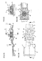
- FIG. 1 shows an assembly 1 comprising a support rail 2, vibration damper 3 and retaining pins 4.
- each four vibration damper 3 and four retaining pins 4 are shown, although in the assembled arrangement 1 according to the illustrated embodiment, only two vibration damper 3 and retaining pins 4 are required.
- the doubling of the illustrated components is solely for the better representation of the vibration damper 3 and retaining pins 4 in different views.
- the support rail 2 comprises contact surfaces 5 which the support rail 2 in the installed state in the vertical direction between in the FIG. 1 Set holding elements not shown a built-in cage of a computer.
- the retaining rail 2 further contact surfaces which define the retaining rail in the installed state in the horizontal direction. These contact surfaces have in the representation of FIG. 1 but down and therefore are not apparent.
- the contact surfaces 5 are arranged on spring elements 6, which cause a shock absorption between the support rail 2 and the installation cage.
- a locking lug 8 is arranged in the region of an end piece 7.
- the locking lug 8 engages in the installed state in an opening of the mounting cage and thus sets the retaining rail 2 in the direction of insertion on the mounting cage.
- the end piece 7 can be easily bent relative to the retaining rail 2 to release the latch to allow removal of a once installed plug-in module.
- the arrangement 1 has a contact spring 9, which produces an electrical contact between a wall of the installation cage and a fixed to the support rail 2 plug-in module.
- the contact spring 9 is made of sheet metal and designed such that it may partially include the support rail 2 and is attachable to this.
- the spring force of the contact spring 9 is designed so that only a negligible transmission of mechanical vibrations by the contact spring 9 is possible.
- the support rail 2 is in the embodiment of a solid plastic material, such as polycarbonate Acrylonitrile-butadiene-styrene (PC / ABS) plastic, and has two first openings 10, which serve to fit the vibration damper 3.
- the first opening 10 comprises two first latching lugs 11, which are arranged in a first direction with respect to the axis of symmetry of the first opening 10, in the insertion direction in the exemplary embodiment.
- the first locking lugs 11 engage in a first circumferential groove 12 of the vibration damper 3.
- the vibration dampers 3 are made of an elastic material such as ethylene-propylene-diene rubber (EPDM) or other suitable elastomer and dampen in particular resonant vibrations, such as occur in the operation of particularly high-speed storage drives such as hard drives or DVD drives.
- the vibration dampers 3 have substantially the shape of a cup or pot, wherein the first circumferential groove 12 is disposed on the outside of the lateral surface directly below a collar.
- the damping of vibrations caused by plug-in modules is particularly important in the case of several storage drives arranged in a common installation cage. Due to the now usual, very high speeds and writing densities, the positioning of writing and reading heads must be done very quickly and accurately. A disturbance of the positioning caused by a vibration leads to a relatively time-consuming readjustment, which increases the access time and reduces the data transmission rate.
- the retaining pins 4 are made of a hard material, such as metal. For example, they may be turned parts which have a pin separated by a collar and a head piece with the second circumferential groove 14. The pins are dimensioned such that they can intervene in particular in usually for screwing plug-in modules imaginary mounting holes.
- the vibration dampers 3 are arranged in the first openings 10 such that the first latching lugs 11 and the second latching lugs 13 are arranged offset in the inserted state by 90 degrees to each other.
- the second locking lugs 13 are arranged in the illustrated embodiment in a vertical direction, that is perpendicular to the insertion direction in which the first locking lugs 11 are arranged. In this way, a direct transmission of vibrations by a pinch of the vibration damper 3 between the first locking lugs 11 and the second locking lug 13 is avoided.
- FIG. 2A shows a first longitudinal section through the arrangement 1 in the region of the end piece 7 and the front first opening 10.
- the first locking lugs 11 engage in this direction in the circumferential groove 12 of the vibration damper 3, in the extension of this line
- an air gap in the second circumferential groove 14 of the retaining pin 4 mechanically decoupled from the support rail 2.
- the collar of the vibration damper 3 rests on the support rail 2, so that the vibration damper 3 can not pass through the support rail 2.
- it is also possible to use the bottom of the first Partially close the opening 10, as in the FIG. 2A is shown.
- FIG. 2B is a plan view of a drawer assembly on the support rail 2 with the end piece 7 arranged thereon.
- the retaining pin 4 is completely isolated mechanically from the retaining rail 2 by the collar of the vibration damper 3.
- the first opening 10 is formed in the region between two further spring elements 15.
- the spring elements 15 further dampen the forces, in particular heavy impacts, between the installation cage and the slide-in module.
- the holding rail 2 facing side of the end piece 7 has two stops 21 which protrude above and below the upper or lower edge of the support rail 2 and set this in the insertion direction. The determination is made below on the basis of FIG. 3 further explained.
- the stops 21 are spatially arranged in the vicinity of the locking lug 8. In this way, a disturbing influence of the different length expansion of the materials involved in heating during operation, for example, a plastic of the support rail 2 and a metal of a mounting cage as far as possible avoided. Also influencing factors other than the temperature, for example one by a high ambient humidity attempted hygroscopic longitudinal expansion, can be avoided in this way.
- FIG. 2C a cross section through the front first opening 10 is shown.
- the engagement of the second locking lugs 13 in the circumferential groove 14 of the retaining pins 4 can be seen.
- Towards the in the Figure 2C illustrated cross section along the axis BB remains an air gap between the support rail 2 and the vibration damper 3 in the region of the second locking lugs 13, so that a mechanical decoupling of the retaining pin 4 is ensured by the support rail 2 in this direction.
- the vibration damper 3 is partially closed at its lower end, so that both a passage of the retaining pin 4 and a direct mechanical contact between the retaining pin 4 and the retaining rail 2 is prevented.
- FIG. 2D shows a second longitudinal section of the arrangement 1 in the region of the first opening 10.
- the second longitudinal section through the first opening 10 along the axis CC shows the spring elements 15 particularly well.
- the first latching lugs 11 and the second latching lugs 13 are offset by 90 degrees relative to one another in order to ensure mechanical decoupling of the retaining pin from the retaining rail 2 in two directions orthogonal to each other and to the axis of symmetry of the retaining pin 4.
- FIG. 3 shows a built-in cage 16 of a computer, not shown, in which a first plug-in module 17 is to be determined by means of two arrangements 1.
- the first drawer assembly 17 is shown in an only partially retracted condition for the interaction of the various elements of the assembly 1 with the mounting cage 16 and the drawer assembly 17.
- a second, in the FIG. 3 predominantly hidden, plug-in module 17 is shown behind the first plug-in module 17 in the fully inserted state.
- the built-in cage 16 has various holding elements 18 which cooperate with the contact surfaces 5 of the arrangement 1. Furthermore, further contact surfaces 19 cooperate with side walls of the installation cage 16.
- the installation cage 16 is made of metal sheets, from which the holding elements 18 are bent out.
- the locking lug 8 in the region of the end piece 7 engages in the inserted state in an opening 20 of the mounting cage 16 a.
- the stops 21 of the end piece 7 fix the retaining rail 2 in the insertion direction, so that the insertion assembly 17 is fixed in the completely inserted state in all spatial directions within the installation cage 16.
- the installation cage 16 out bent stop surfaces 22 above or below the opening 20, which cooperate with the stops 21 in the fully inserted state.
- the installation cage 16 and the support rails 2 have additional means for transport safety. Through them, one or more retaining rails 2 without built-in plug-in modules 17 in the built-in cage 16 are attached so that they are available for later installation of further plug-in modules 17.
- each of the support rails 2 each comprises two tabs 24 which engage in the retracted state behind parts of the front support members 18 to secure them against falling out.
- FIG. 4 shows in each case a front and rear view of a composite arrangement 1.
- the arrangement 1 provides four different functions. First, it allows a screw and tool-free determination of a drawer assembly 17 in a mounting cage 16. For this purpose, the assembled arrangements 1 need only be laterally attached to the plug-in module 17 and inserted together with it in the mounting cage 16.
- the spring elements 6 and 15 as well as the curved contact surfaces 19, which are also designed as spring elements in the exemplary embodiment, provide shock absorption between the installation cage 16 and the plug-in module 17 when installed.
- the vibration dampers 3 effectively suppress self-vibration of the slide-in assembly 17 as well as vibration transmission from adjacent slide-in assemblies 17.
- plug-in modules 17 which are not dependent on a ground connection on the housing, for example because this is provided via a connecting line, can of course be dispensed with the fourth function and thus also on the contact spring 9.
- the other functions and associated features are dispensable, as far as they are not used in a specific arrangement.
Landscapes
- Engineering & Computer Science (AREA)
- Theoretical Computer Science (AREA)
- Computer Hardware Design (AREA)
- General Engineering & Computer Science (AREA)
- Power Engineering (AREA)
- Human Computer Interaction (AREA)
- Physics & Mathematics (AREA)
- General Physics & Mathematics (AREA)
- Connector Housings Or Holding Contact Members (AREA)
- Vibration Prevention Devices (AREA)
- Mounting Of Printed Circuit Boards And The Like (AREA)
- Mounting Components In General For Electric Apparatus (AREA)
Abstract
Description
Die Erfindung betrifft eine Anordnung zum Festlegen einer Einschubbaugruppe in einem Einbaukäfig eines Computers, aufweisend eine Halteschiene mit wenigstens einer Kontaktfläche zum Festlegen der Halteschiene in dem Einbaukäfig und wenigstens einem Haltestift zum Eingreifen in eine seitliche Befestigungsöffnung der Einschubbaugruppe, wobei die Halteschiene durch den wenigstens einen Haltestift seitlich an der Einschubbaugruppe festlegbar ist.The invention relates to an arrangement for securing a drawer assembly in a built-in cage of a computer, comprising a retaining rail having at least one contact surface for fixing the retaining rail in the mounting cage and at least one retaining pin for engaging in a lateral mounting opening of the drawer assembly, wherein the retaining rail through the at least one retaining pin can be fixed laterally on the plug-in module.
Aus der
Halteschienen aus einem einzelnen Material können die geforderten Dämpfung meist nur ungenügend erbringen, da sie keine hinreichende Möglichkeit bieten, ihre Dämpfungseigenschaften an die teilweise sehr speziellen Anforderungen anzupassen.Retaining rails made of a single material can provide the required attenuation usually insufficient, since they do not provide sufficient opportunity to adapt their damping properties to the sometimes very special requirements.
Anordnungen aus Verbundmaterialien, wie sie etwa im so genannten Zweikomponenten-Spritzgussverfahren hergestellt werden können, bereiten unter anderem beim Recycling große Probleme, weil die darin verwendeten Kunststoffe nicht einfach voneinander getrennt werden können.Arrangements of composite materials, such as those which can be produced in the so-called two-component injection molding process, cause great problems, inter alia, in recycling. because the plastics used therein can not be easily separated from each other.
Anordnungen bestehend aus mehreren, ineinander greifenden Halteschienen sind zwar leichter wieder zu verwerten, aber aufwändiger und teurer in der Herstellung. Zudem können solche Anordnungen zwar Stöße dämpfen, verhindern aber nicht unbedingt das Auftreten von Resonanzschwingungen, wie sie etwa bei besonders hochtourigen Speicherlaufwerken mit großen Schreibdichten auftreten.Arrangements consisting of several, interlocking support rails are indeed easier to recycle, but more complex and expensive to manufacture. In addition, such arrangements can dampen shocks, but not necessarily prevent the occurrence of resonant vibrations, such as occur in very high-speed storage drives with large write densities.
Aufgabe der vorliegenden Erfindung ist es daher, eine besonders einfach aufgebaute und leicht wieder zu verwendende Haltevorrichtung für Einschubbaugruppen anzugeben, die sowohl Schwingungen als auch Stöße wirksam dämpft.Object of the present invention is therefore to provide a particularly simple design and easy to reuse holding device for plug-in modules, which effectively damps both vibrations and shocks.
Die zugrunde liegende Aufgabe wird durch eine Anordnung zum Festlegen einer Einschubbaugruppe der oben genannten Art gelöst, die dadurch gekennzeichnet ist, dass in der Halteschiene wenigstens eine erste Öffnung ausgebildet ist, wenigstens ein topfartig ausgeformte Schwingungsdämpfer aus einem elastischen Material klemmend in der ersten Öffnung aufgenommen ist und der wenigstens eine Haltestift klemmend in dem Schwingungsdämpfer aufgenommen ist, wobei der Schwingungsdämpfer den Haltestift zumindest teilweise mantelförmig umgibt.The underlying object is achieved by an arrangement for fixing a plug-in module of the abovementioned type, which is characterized in that at least one first opening is formed in the retaining rail, at least one pot-shaped vibration damper made of an elastic material is received by clamping in the first opening and the at least one retaining pin is received by clamping in the vibration damper, wherein the vibration damper surrounds the retaining pin at least partially jacket-shaped.
Die einzelnen Teile der oben angegebenen Anordnung können in ihren Materialeigenschaften an die erforderlichen Dämpfungseigenschaften angepasst werden. Durch den mantelförmigen Schwingungsdämpfer wird eine direkte Schwingungsübertragung zwischen dem Haltestift und der Halteschiene unterbunden.The individual parts of the above arrangement can be adapted in their material properties to the required damping properties. The jacket-shaped vibration damper prevents direct vibration transmission between the retaining pin and the retaining rail.
Zugleich wird durch die klemmende Montage der Einzelteile eine einfache Zerlegung der Anordnung zum Recycling ermöglicht.At the same time a simple disassembly of the arrangement for recycling is made possible by the clamping assembly of the items.
Gemäß einer vorteilhaften Ausgestaltung weist der Schwingungsdämpfer eine an seiner Außenseite umlaufende erste Nut auf, und die Halteschiene weist im Bereich der ersten Öffnung wenigstens eine erste Rastnase auf, die in die erste umlaufende Nut des Schwingungsdämpfers eingreift. Durch Verwendung einer umlaufenden Nut und einer Rastnase kann der Schwindungsdämpfer durch Verrasten mit der Halteschiene werkzeug- und klebstofffrei festgelegt werden.According to an advantageous embodiment, the vibration damper has a circumferential on its outer side of the first groove, and the holding rail has in the region of the first opening at least a first latching lug which engages in the first circumferential groove of the vibration damper. By using a circumferential groove and a locking lug, the shrinkage damper can be fixed by latching with the retaining rail tool and adhesive-free.
Gemäß einer weiteren vorteilhaften Ausgestaltung weist der Haltestift eine auf seine Außenseite umlaufende zweite Nut auf, und der Schwingungsdämpfer weist auf seiner Innenseite wenigstens eine zweite Rastnase auf, die in die zweite umlaufende Nut des Haltestifts eingreift. Durch Verwendung einer zweiten umlaufenden Nut und einer zweiten Rastnase kann auch der Haltestift werkzeug- und klebstofffrei an dem Schwingungsdämpfer festgelegt werden.According to a further advantageous embodiment, the retaining pin has a circumferential on its outer side second groove, and the vibration damper has on its inner side at least a second latching lug which engages in the second circumferential groove of the retaining pin. By using a second circumferential groove and a second locking lug and the retaining pin tool and glue-free can be set to the vibration damper.
Gemäß einer weiteren vorteilhaften Ausgestaltung sind die erste und zweite Rastnase bezogen auf die Symmetrieachse des Haltestiftes um etwa 90 Grad voneinander versetzt angeordnet. Durch die versetzte Anordnung der ersten und zweiten Rastnase wird die Schwingungsdämpfung durch den Schwingungsdämpfer optimiert, da der erste und zweite Rastmechanismus mechanisch voneinander entkoppelt werden.According to a further advantageous embodiment, the first and second locking lug are arranged offset from each other by about 90 degrees relative to the axis of symmetry of the retaining pin. Due to the staggered arrangement of the first and second latching lug, the vibration damping is optimized by the vibration damper, since the first and second latching mechanism are mechanically decoupled from each other.
Gemäß einer weiteren vorteilhaften Ausgestaltung ist wenigstens eine elektrisch leitfähige Kontaktfeder an der Halteschiene angeordnet, durch die ein elektrischer Kontakt zwischen der Einschubbaugruppe und dem Einbaukäfig herstellbar ist. Durch Verwendung einer elektrisch leitfähigen Kontaktfeder kann eine sichere Masseverbindung zwischen der Einschubbaugruppe und dem Einbaukäfig auch dann hergestellt werden, wenn die Einschubbaugruppe durch das Dämpfungselement mechanisch und elektrisch von dem Einbaukäfig entkoppelt ist.According to a further advantageous embodiment, at least one electrically conductive contact spring is arranged on the retaining rail, can be produced by the electrical contact between the plug-in module and the mounting cage is. By using an electrically conductive contact spring, a secure ground connection between the plug-in module and the installation cage can also be produced when the plug-in module is mechanically and electrically decoupled from the installation cage by the damping element.
Die zugrunde liegende Aufgabe wird ebenso durch ein Verfahren zum Festlegen einer Einschubbaugruppe in einem Computer mit den folgenden Schritten gelöst:
- Bereitstellen einer Halteschiene mit wenigstens einer ersten Öffnung,
- Einstecken wenigstens eines topfförmigen Schwingungsdämpfers aus einem elastischen Material in die erste Öffnung,
- Einstecken wenigstens eines Haltestiftes in den Schwingungsdämpfer,
- seitliches Aufstecken der Halteschiene auf die Einschubbaugruppe durch Einführen des Haltestiftes in wenigstens eine Befestigungsöffnung der Einschubbaugruppe und
- Einschieben der Baugruppe in einem Einbaukäfig des Computers, wobei wenigstens eine Kontaktfläche der Halteschiene mit wenigstens einem Halteelement des Einbaukäfigs zusammenwirkt und die Halteschiene in der Einschubbaugruppe festlegt.
- Providing a retaining rail with at least one first opening,
- Inserting at least one cup-shaped vibration damper made of an elastic material into the first opening,
- Inserting at least one retaining pin into the vibration damper,
- lateral attachment of the retaining rail on the slide-in module by inserting the retaining pin in at least one mounting opening of the slide-in module and
- Inserting the module in a built-in cage of the computer, wherein at least one contact surface of the retaining rail cooperates with at least one retaining element of the mounting cage and determines the retaining rail in the slide-in module.
Weitere Einzelheiten und Ausgestaltungen der Erfindung sind in den Unteransprüchen angegeben.Further details and embodiments of the invention are specified in the subclaims.
Die Erfindung wird nachfolgend an einem Ausführungsbeispiel anhand der Zeichnungen näher erläutert. In den Zeichnungen zeigen:
- Figur 1
- eine Explosionsdarstellung einer Anordnung zur Festlegung einer Einschubbaugruppe,
- Figur 2A
- einen ersten Längsschnitt durch die Anordnung zur Festlegung einer Einschubbaugruppe,
- Figur 2B
- eine Draufsicht auf die Anordnung zur Festlegung der Einschubbaugruppe,
- Figur 2C
- einen Querschnitt durch die Anordnung zur Festlegung einer Einschubbaugruppe,
- Figur 2D
- einen zweiten Längsschnitt durch die Anordnung zur Festlegung einer Einschubbaugruppe,
Figur 3- einen Einbaukäfig eines Computers mit zwei Einschubbaugruppen und
Figur 4- jeweils eine Vorder- und Rückansicht einer zusammengesetzten Anordnung zur Festlegung einer Einschubbaugruppe.
- FIG. 1
- an exploded view of an arrangement for determining a slide-in module,
- FIG. 2A
- a first longitudinal section through the arrangement for determining a slide-in module,
- FIG. 2B
- a top view of the arrangement for fixing the slide-in module,
- Figure 2C
- a cross-section through the arrangement for determining a slide-in module,
- FIG. 2D
- a second longitudinal section through the arrangement for determining a slide-in module,
- FIG. 3
- a built-in cage of a computer with two plug-in modules and
- FIG. 4
- each a front and rear view of an assembled assembly for defining a plug-in module.
Die Halteschiene 2 umfasst Kontaktflächen 5 die die Halteschiene 2 im eingebauten Zustand in vertikaler Richtung zwischen in der
An einem Ende der Halteschiene 2 ist im Bereich eines Endstücks 7 eine Rastnase 8 angeordnet. Die Rastnase 8 greift im eingebauten Zustand in eine Öffnung des Einbaukäfigs ein und legt die Halteschiene 2 somit in Einschubrichtung an dem Einbaukäfig fest. Das Endstück 7 kann zum Lösen der Verrastung leicht gegenüber der Halteschiene 2 abgebogen werden, um ein Herausnehmen eines einmal eingebauten Einschubmoduls zu ermöglichen.At one end of the retaining
Zusätzlich weist die Anordnung 1 eine Kontaktfeder 9 auf, die einen elektrischen Kontakt zwischen einer Wand des Einbaukäfigs und einer an der Halteschiene 2 festgelegten Einschubbaugruppe herstellt. Im Ausführungsbeispiel ist die Kontaktfeder 9 aus Metallblech gefertigt und derart ausgestaltet, dass sie die Halteschiene 2 teilweise umfassen kann und so an dieser befestigbar ist. Die Federkraft der Kontaktfeder 9 ist so ausgelegt, dass nur eine vernachlässigbare Übertragung mechanischer Schwingungen durch die Kontaktfeder 9 möglich ist.In addition, the arrangement 1 has a
Die Halteschiene 2 besteht im Ausführungsbeispiel aus einem festen Kunststoffmaterial, wie beispielsweise aus Polycarbonat Acrylnitril-Butadien-Styrol (PC/ABS) Kunststoff, und weist zwei erste Öffnungen 10 auf, die zum Einpassen der Schwingungsdämpfer 3 dienen. Die erste Öffnung 10 umfasst hierfür zwei erste Rastnasen 11, die in einer ersten Richtung mit Bezug auf die Symmetrieachse der ersten Öffnung 10, im Ausführungsbeispiel in der Einschubrichtung, angeordnet sind.The
Die ersten Rastnasen 11 greifen in eine erste umlaufende Nut 12 der Schwingungsdämpfer 3 ein. Die Schwingungsdämpfer 3 sind aus einem elastischen Material beispielsweise Ethylen-Propylen-Dien-Kautschuk (EPDM) oder einem anderen geeigneten Elastomer gefertigt und dämpfen insbesondere Resonanzschwingungen, wie sie beim Betrieb besonders hochtouriger Speicherlaufwerken wie Festplatten oder DVD-Laufwerken auftreten. Die Schwingungsdämpfer 3 haben im Wesentlichen die Form eines Bechers oder Topfes, wobei die erste umlaufende Nut 12 auf der Außenseite der Mantelfläche direkt unterhalb eines Kragens angeordnet ist.The first locking lugs 11 engage in a first
Die Dämpfung von durch Einschubbaugruppen verursachten Schwingungen ist insbesondere bei mehreren, in einem gemeinsamen Einbaukäfig angeordneten Speicherlaufwerken wichtig. Durch die mittlerweile üblichen, sehr hohe Drehzahlen und Schreibdichten, muss auch die Positionierung von Schreib- und Leseköpfen sehr schnell und zielgenau erfolgen. Eine durch eine Schwingung verursachte Störung der Positionierung führt dabei zu einer verhältnismäßigen zeitaufwändigen Nachregelung, die die Zugriffszeit vergrößert und die Datenübertragungsrate vermindert.The damping of vibrations caused by plug-in modules is particularly important in the case of several storage drives arranged in a common installation cage. Due to the now usual, very high speeds and writing densities, the positioning of writing and reading heads must be done very quickly and accurately. A disturbance of the positioning caused by a vibration leads to a relatively time-consuming readjustment, which increases the access time and reduces the data transmission rate.
Auf der Innenseite der Mantelfläche sind zwei zweite Rastnasen 13 angeordnet, die in eine zweite umlaufende Nut 14 auf der Außenseite der Haltestifte 4 eingreifen. Die Haltestifte 4 sind aus einem harten Material, beispielsweise aus Metall gefertigt. Beispielsweise kann es sich um Drehteile handeln, die einen durch einen Kragen getrennten Stift und ein Kopfstück mit der zweiten umlaufenden Nut 14 aufweisen. Die Stifte sind derart dimensioniert, dass sie insbesondere in üblicherweise zur Verschraubung von Einschubbaugruppen gedachten Befestigungsöffnungen eingreifen können.On the inside of the lateral surface two second locking lugs 13 are arranged, which engage in a second
Um die Dämpfungseigenschaften der dargestellten Anordnung zu optimieren, werden die Schwingungsdämpfer 3 derart in den ersten Öffnungen 10 angeordnet, dass die ersten Rastnasen 11 und die zweiten Rastnasen 13 im eingesetzten Zustand um 90 Grad zueinander versetzt angeordnet sind. Beispielsweise sind die zweiten Rastnasen 13 im dargestellten Ausführungsbeispiel in einer vertikalen Richtung angeordnet, also senkrecht zur Einschubrichtung, in der die ersten Rastnasen 11 angeordnet sind. Auf diese Weise wird eine direkte Übertragung von Schwingungen durch eine Quetschung der Schwingungsdämpfer 3 zwischen den ersten Rastnasen 11 und den zweiten Rastnase 13 vermieden.In order to optimize the damping properties of the illustrated arrangement, the
In der
Zur weiteren Optimierung der Dämpfungseigenschaften der Halteschiene 2 ist die erste Öffnung 10 im Bereich zwischen zwei weiteren Federelementen 15 ausgebildet. Die Federelemente 15 dämpfen die Kräfte insbesondere starker Stöße zwischen dem Einbaukäfig und der Einschubbaugruppe weiter ab.To further optimize the damping properties of the retaining
Zudem ist in der
Die Anschläge 21 sind räumlich in der Nähe der Rastnase 8 angeordnet. Auf diese Weise wird ein störender Einfluss der unterschiedlichen Längenausdehnung der beteiligten Materialen bei Erwärmung im Betrieb, zum Beispiel eines Kunststoffes der Halteschiene 2 und eines Metalls eines Einbaukäfigs soweit wie möglich vermieden. Auch andere Einflussgrößen als die Temperatur, beispielsweise eine durch eine hohe Umgebungsfeuchtigkeit versuchte hygroskopisch bedingte Längenausdehnung, können auf diese Weise vermieden werden.The stops 21 are spatially arranged in the vicinity of the locking lug 8. In this way, a disturbing influence of the different length expansion of the materials involved in heating during operation, for example, a plastic of the
In der
Der Einbaukäfig 16 weist verschiedene Halteelemente 18 auf, die mit den Kontaktflächen 5 der Anordnung 1 zusammenwirken. Des Weiteren wirken weitere Kontaktflächen 19 mit Seitenwänden des Einbaukäfigs 16 zusammen. Im Ausführungsbeispiel ist der Einbaukäfig 16 aus Metallblechen hergestellt, aus denen die Halteelemente 18 heraus gebogen sind.The built-in
Die Rastnase 8 im Bereich des Endstückes 7 greift im eingeschobenen Zustand in eine Öffnung 20 des Einbaukäfigs 16 ein. Gleichzeitig legen die Anschläge 21 des Endstücks 7 die Halteschiene 2 in Einschubrichtung fest, so dass die Einschubbaugruppe 17 im vollständig eingeschobenen Zustand in allen Raumrichtungen innerhalb des Einbaukäfigs 16 festgelegt ist.The locking lug 8 in the region of the
Hierzu weist der Einbaukäfig 16 heraus gebogene Anschlagflächen 22 ober- beziehungsweise unterhalb der Öffnung 20 auf, die mit den Anschlägen 21 im vollständig eingeschobenen Zustand zusammenwirken. Zum Herausziehen der Einschubbaugruppe 17 müssen die zwei Endstücke 7, die als einziges Teil der Halteschiene 2 über die Einschubbaugruppe 17 hinausragen, nur zusammengedrückt werden, um die Verrastung der Rastnase 8 zu lösen und ein einfaches Herausziehen der Einschubbaugruppe 17 zu ermöglichen.For this purpose, the
In dem dargestellten Ausführungsbeispiel verfügen der Einbaukäfig 16 sowie die Halteschienen 2 über zusätzliche Mittel zur Transportsicherung. Durch sie können ein oder mehrere Halteschienen 2 auch ohne eingebaute Einschubbaugruppen 17 in dem Einbaukäfig 16 befestigt werden, so dass diese für einen späteren Einbau von weiteren Einschubbaugruppen 17 zur Verfügung stehen.In the illustrated embodiment, the
Hierzu legen heraus gebogene Haltebrücken 23 die Halteschiene 2 im eingeschobenen Zustand auch ohne eingebaute Einschubbaugruppe 17 im Einbaukäfig 16 fest. Anhand der zweiten, bereits vollständig eingeschobenen Einschubbaugruppe 17 ist zu erkennen, dass ein hinteres Endstück 25 der Halteschienen 2 zu dessen Fixierung hinter die heraus gebogenen Haltebrücken 23 fasst. Des Weiteren umfasst jede der Halteschienen 2 jeweils zwei Laschen 24, die im eingeschobenen Zustand hinter Teile der vorderen Haltelemente 18 greifen, um diese gegen ein Herausfallen zu sichern.For this purpose, out bent retaining bridges 23, the retaining
Zum Zweiten bieten die Federelemente 6 und 15 sowie die im Ausführungsbeispiel ebenfalls als Federelemente ausgeführten, gebogenen Kontaktflächen 19 im eingebauten Zustand eine Stoßdämpfung zwischen Einbaukäfig 16 und Einschubbaugruppe 17.Secondly, the
Drittens unterdrücken die Schwingungsdämpfer 3 wirkungsvoll Eigenschwingungen der Einschubbaugruppe 17 sowie eine Schwingungsübertragung von benachbarten Einschubbaugruppen 17.Third, the
Viertens wird durch die Kontaktfeder 9 eine sichere Masseverbindung zwischen der Einschubbaugruppe 17 und dem Einbaukäfig 16 hergestellt. Bei Einschubbaugruppen 17, die nicht auf eine Masseverbindung über das Gehäuse angewiesen sind, beispielsweise weil diese über eine Anschlussleitung bereitgestellt wird, kann auf die vierte Funktion und damit auch auf die Kontaktfeder 9 selbstverständlich verzichtet werden.Fourth, a secure ground connection between the plug-in
Auch die anderen Funktionen und damit verbundenen Merkmale sind verzichtbar, soweit sie in einer konkreten Anordnung nicht verwendet werden. Beispielsweise kann auf die Federelemente 6 und 15 versichtet werden, wenn die Stoßdämpfungsfunktion nicht benötigt oder auf andere Weise zur Verfügung gestellt wird. Zudem ist es möglich, die an sich schraubenlose Anordnung 1 durch zusätzliche Schrauben oder ähnliche Befestigungselemente zu sichern, um ein versehentliches Herausziehen einzelner Einschubbaugruppen im Betrieb zu verhindern.The other functions and associated features are dispensable, as far as they are not used in a specific arrangement. For example, can be made to the
Da die Haltestifte 4 mit dem Schwingungsdämpfer 3 und die Schwingungsdämpfer 3 mit der Halteschiene 2 lediglich verrastet oder, gemäß einer weiteren, nicht dargestellten Ausführungsform, in diese formschlüssig eingeklemmt sind, ist ein leichtes Trennen der unterschiedlichen Elemente der Anordnung 1 möglich. Auf diese Weise wird die Anordnung 1 der so genannten RoHS (Restriction of the use of certain hazardous substances in electrical and electronic equipment) Richtlinie der europäischen Gemeinschaft
- 11
- Anordnungarrangement
- 22
- Halteschieneretaining rail
- 33
- Schwingungsdämpfervibration
- 44
- Haltestiftretaining pin
- 55
- Kontaktflächecontact area
- 66
- Federelementspring element
- 77
- (vorderes) Endstück(front) tail
- 88th
- Rastnaselocking lug
- 99
- Kontaktfedercontact spring
- 1010
- erste Öffnungfirst opening
- 1111
- erste Rastnasefirst catch
- 1212
- erste umlaufende Nutfirst circumferential groove
- 1313
- zweite Rastnasesecond catch
- 1414
- zweite umlaufende Nutsecond circumferential groove
- 1515
- Federelementspring element
- 1616
- Einbaukäfiginstallation cage
- 1717
- Einschubbaugruppeinsert unit
- 1818
- Halteelementretaining element
- 1919
- Kontaktflächecontact area
- 2020
- Öffnungopening
- 2121
- Anschlagattack
- 2222
- Anschlagflächestop surface
- 2323
- Haltebrückeretaining bridge
- 2424
- Lascheflap
- 2525
- (hinteres) Endstück(rear) tail
Claims (12)
dadurch gekennzeichnet, dass
der Schwingungsdämpfer (3) eine auf seiner Außenseite erste umlaufende Nut (12) aufweist und die Halteschiene (2) im Bereich der ersten Öffnung (10) wenigstens eine erste Rastnase (11) aufweist, die in die erste umlaufende Nut (12) des Schwingungsdämpfers (3) eingreift.Arrangement (1) according to claim 1,
characterized in that
the vibration damper (3) has a first circumferential groove (12) on its outer side, and the retaining rail (2) has at least one first latching lug (11) in the region of the first opening (10) which projects into the first circumferential groove (12) of the vibration damper (3) intervenes.
dadurch gekennzeichnet, dass
der Haltestift (4) eine auf seiner Außenseite zweite umlaufende Nut (14) aufweist und der Schwingungsdämpfer (3) auf seiner Innenseite wenigstens eine zweite Rastnase (13) aufweist, die in die zweite umlaufende Nut (14) des Haltestiftes (4) eingreift.Arrangement (1) according to claim 1 or 2,
characterized in that
the retaining pin (4) has a second peripheral groove (14) on its outer side and the vibration damper (3) has on its inside at least one second latching lug (13) which engages in the second circumferential groove (14) of the retaining pin (4).
dadurch gekennzeichnet, dass
der Haltestift (4) eine auf seiner Außenseite zweite umlaufende Nut (14) aufweist und der Schwingungsdämpfer (3) auf seiner Innenseite wenigstens eine zweite Rastnase (13) aufweist, die in die zweite umlaufende Nut (14) des Haltestiftes (4) eingreift, wobei die erste Rastnase (11) und die zweite Rastnase (13) bezogen auf die Symmetrieachse des Haltestiftes (4) um etwa 90 Grad versetzt angeordnet sind.Arrangement (1) according to claim 2,
characterized in that
the retaining pin (4) has a second peripheral groove (14) on its outer side and the vibration damper (3) has on its inside at least one second latching lug (13) which engages in the second circumferential groove (14) of the retaining pin (4), wherein the first latching lug (11) and the second latching lug (13) are offset by approximately 90 degrees relative to the axis of symmetry of the retaining pin (4).
dadurch gekennzeichnet, dass
die Halteschiene (2) wenigstens zwei erste Öffnungen (10) aufweist, in denen jeweils ein topfartiger Schwingungsdämpfer (3) aufgenommen ist, wobei in jedem der Schwingungsdämpfer (3) jeweils ein Haltestift (4) zur Festlegung der Halteschiene (2) an Befestigungsöffnungen der Einschubbaugruppe (17) aufgenommen ist.Arrangement (1) according to one of claims 1 to 4,
characterized in that
the retaining rail (2) has at least two first openings (10), in each of which a cup-like vibration damper (3) is accommodated, wherein in each of the vibration dampers (3) a holding pin (4) for fixing the retaining rail (2) to fastening openings of the Insertion module (17) is received.
dadurch gekennzeichnet, dass
die Halteschiene (2) wenigstens eine erste Kontaktfläche (5) und eine zweite Kontaktfläche (19) aufweist, die die Halteschiene (2) in vertikaler beziehungsweise horizontaler Richtung in dem Einbaukäfig (16) festlegen.Arrangement (1) according to one of claims 1 to 5,
characterized in that
the retaining rail (2) has at least one first contact surface (5) and a second contact surface (19) which fix the retaining rail (2) in the vertical or horizontal direction in the installation cage (16).
dadurch gekennzeichnet, dass
die wenigstens eine Kontaktfläche (5, 19) im Bereich eines Federelementes (6) der Halteschiene (2) angeordnet ist.Arrangement (1) according to one of claims 1 to 6,
characterized in that
the at least one contact surface (5, 19) in the region of a spring element (6) of the retaining rail (2) is arranged.
dadurch gekennzeichnet, dass
die Halteschiene (2) wenigstens einen Anschlag (21) aufweist, der die Halteschiene (2) in Einschubrichtung festlegt.Arrangement (1) according to one of claims 1 to 7,
characterized in that
the retaining rail (2) has at least one stop (21) which defines the retaining rail (2) in the direction of insertion.
dadurch gekennzeichnet, dass
die Halteschiene (2) eine dritte Rastnase (8) zum Verrasten der Halteschiene (2) mit einem Gegenrastelement des Einbaukäfigs (16) aufweist, wobei die dritte Rastnase (8) die Einschubbaugruppe (17) in einer vollständig eingeschobenen Position in dem Einbaukäfig (16) festlegt.Arrangement (1) according to one of claims 1 to 8,
characterized in that
the retaining rail (2) has a third latching lug (8) for latching the retaining rail (2) with a counter-latching element of the installation cage (16), wherein the third latching lug (8) engages the slide-in module (17) in a fully inserted position in the installation cage (16 ).
dadurch gekennzeichnet, dass
an der Halteschiene (2) wenigstens eine elektrisch leitfähig Kontaktfeder (9) angeordnet ist, durch die ein elektrischer Kontakt zwischen der Einschubbaugruppe (17) und dem Einbaukäfig (16) herstellbar ist.Arrangement (1) according to one of claims 1 to 9,
characterized in that
on the retaining rail (2) at least one electrically conductive contact spring (9) is arranged, through which an electrical contact between the plug-in module (17) and the installation cage (16) can be produced.
dadurch gekennzeichnet, dass
an der Halteschiene (2) und/oder dem Einbaukäfig (16) Mittel zur Transportsicherung der Halteschiene (2) in dem Einbaukäfig (16) vorgesehen sind, so dass die Halteschiene (2) auch ohne aufgesteckte Einschubbaugruppe (17) in dem Einbaukäfig (16) befestigbar ist.Arrangement (1) according to one of claims 1 to 10,
characterized in that
on the retaining rail (2) and / or the mounting cage (16) means for securing the retaining rail (2) in the mounting cage (16) are provided so that the retaining rail (2) without plugged-in subassembly (17) in the mounting cage (16 ) is attachable.
Applications Claiming Priority (1)
| Application Number | Priority Date | Filing Date | Title |
|---|---|---|---|
| DE200710024896 DE102007024896B3 (en) | 2007-05-29 | 2007-05-29 | Insertion component e.g. diskette drive, fixing arrangement for computer, has holding pin held in vibration damper in clamped manner, and vibration damper that partially surrounds holding pin in mantle shaped manner |
Publications (2)
| Publication Number | Publication Date |
|---|---|
| EP2000879A2 true EP2000879A2 (en) | 2008-12-10 |
| EP2000879A3 EP2000879A3 (en) | 2011-11-23 |
Family
ID=39099798
Family Applications (1)
| Application Number | Title | Priority Date | Filing Date |
|---|---|---|---|
| EP08100203A Withdrawn EP2000879A3 (en) | 2007-05-29 | 2008-01-08 | Arrangement and method for fixing a module. |
Country Status (3)
| Country | Link |
|---|---|
| EP (1) | EP2000879A3 (en) |
| CN (1) | CN101315575B (en) |
| DE (1) | DE102007024896B3 (en) |
Families Citing this family (12)
| Publication number | Priority date | Publication date | Assignee | Title |
|---|---|---|---|---|
| US8452148B2 (en) | 2008-08-29 | 2013-05-28 | Corning Cable Systems Llc | Independently translatable modules and fiber optic equipment trays in fiber optic equipment |
| US8712206B2 (en) | 2009-06-19 | 2014-04-29 | Corning Cable Systems Llc | High-density fiber optic modules and module housings and related equipment |
| DE102009033289B4 (en) | 2009-07-06 | 2017-02-09 | Fujitsu Technology Solutions Intellectual Property Gmbh | Arrangement, holding rail and method for defining a plug-in module |
| DE102010048715B4 (en) | 2010-10-19 | 2012-12-27 | Hilscher Gesellschaft für Systemautomation mbH | Self-locking push-in contact arrangement for a usable in a device housing module and module for this purpose |
| DE102010052928B3 (en) | 2010-11-30 | 2012-04-05 | Fujitsu Technology Solutions Intellectual Property Gmbh | Retaining rail for a plug-in module and arrangement |
| DE102011012661B3 (en) * | 2011-02-28 | 2012-07-26 | Christmann Informationstechnik + Medien Gmbh & Co. Kg | Computer equipment, has front-side open housing in which computer components are arranged one above other, where support component of computer components is formed to be overlapped with another support component |
| DE102011100179B3 (en) * | 2011-05-02 | 2012-08-16 | Fujitsu Technology Solutions Intellectual Property Gmbh | Support rail for fastening computer component in mounting cage for computer, has handles which are arranged at base portions and are inserted at front end side of computer component |
| DE102013107372B9 (en) * | 2013-07-11 | 2015-01-08 | Fujitsu Technology Solutions Intellectual Property Gmbh | Arrangement for fixing a built-in component, in particular a hard disk drive, in a computer system and a retaining rail |
| DE102014110407B4 (en) * | 2014-07-23 | 2017-09-21 | Fujitsu Technology Solutions Intellectual Property Gmbh | Arrangement for determining a plug-in module and assembly method |
| DE102016100237B4 (en) * | 2016-01-08 | 2022-03-31 | Omron Corporation | Storage medium recording device, industrial computer and method |
| DE102017126898B3 (en) * | 2017-11-15 | 2018-11-15 | Fujitsu Technology Solutions Intellectual Property Gmbh | Computer system with a built-in cage |
| DE102018222432A1 (en) * | 2018-12-20 | 2020-06-25 | Robert Bosch Gmbh | Gear drive unit |
Citations (1)
| Publication number | Priority date | Publication date | Assignee | Title |
|---|---|---|---|---|
| DE10213526A1 (en) | 2002-03-26 | 2003-10-30 | Fujitsu Siemens Computers Gmbh | Definition of a slide-in module in a mounting cage of a computer |
Family Cites Families (10)
| Publication number | Priority date | Publication date | Assignee | Title |
|---|---|---|---|---|
| US4713714A (en) * | 1985-11-26 | 1987-12-15 | Motorola Computer Systems, Inc. | Computer peripheral shock mount for limiting motion-induced errors |
| US5098175A (en) * | 1989-10-27 | 1992-03-24 | International Business Machines Corporation | Removable guide apparatus for a rail-mounted device employed in a computer |
| CN1163809C (en) * | 2000-07-21 | 2004-08-25 | 富金精密工业(深圳)有限公司 | Slide Rails for Data Storage Units |
| US6600648B2 (en) * | 2001-07-10 | 2003-07-29 | Dell Products L.P. | Mounting rail for hard disk drive |
| EP1282347A1 (en) * | 2001-08-03 | 2003-02-05 | Hewlett-Packard Company, A Delaware Corporation | A housing for a computer sub-assembly comprising a keeper and a support member |
| DE10244887B3 (en) * | 2002-09-26 | 2004-06-03 | Fujitsu Siemens Computers Gmbh | Holding rail for fixing a slide-in module in a mounting cage of a computer |
| CN2636299Y (en) * | 2003-06-24 | 2004-08-25 | 联想(北京)有限公司 | Screw free vibration damper structure for hard disc |
| TWM244556U (en) * | 2003-09-12 | 2004-09-21 | Hon Hai Prec Ind Co Ltd | Mounting apparatus for data storage devices |
| CN1326011C (en) * | 2004-06-18 | 2007-07-11 | 华硕电脑股份有限公司 | Fasteners and Electronic Equipment |
| TWI262375B (en) * | 2004-07-22 | 2006-09-21 | Aopen Inc | Assembling device without the use of tool and host computer case adopting the same |
-
2007
- 2007-05-29 DE DE200710024896 patent/DE102007024896B3/en not_active Expired - Fee Related
-
2008
- 2008-01-08 EP EP08100203A patent/EP2000879A3/en not_active Withdrawn
- 2008-05-27 CN CN2008100977707A patent/CN101315575B/en not_active Expired - Fee Related
Patent Citations (1)
| Publication number | Priority date | Publication date | Assignee | Title |
|---|---|---|---|---|
| DE10213526A1 (en) | 2002-03-26 | 2003-10-30 | Fujitsu Siemens Computers Gmbh | Definition of a slide-in module in a mounting cage of a computer |
Also Published As
| Publication number | Publication date |
|---|---|
| DE102007024896B3 (en) | 2008-05-29 |
| CN101315575B (en) | 2011-10-26 |
| EP2000879A3 (en) | 2011-11-23 |
| CN101315575A (en) | 2008-12-03 |
Similar Documents
| Publication | Publication Date | Title |
|---|---|---|
| DE102007024896B3 (en) | Insertion component e.g. diskette drive, fixing arrangement for computer, has holding pin held in vibration damper in clamped manner, and vibration damper that partially surrounds holding pin in mantle shaped manner | |
| DE19708775C1 (en) | Electronic assembly carrier especially for computer magnetic disc drive | |
| EP1403873B1 (en) | Holding rail for fixing an insertable unit in a computer rack | |
| DE102009033289B4 (en) | Arrangement, holding rail and method for defining a plug-in module | |
| DE102013105552B4 (en) | Arrangement for fixing a plug-in module in a built-in cage of a computer system and retaining rail | |
| DE10203390B4 (en) | guide frame | |
| DE102015122286B3 (en) | Housing for a computer system and computer system | |
| DE102008049329A1 (en) | Lock box housing for lock of glass door, has lock plate or lock cover comprising spacer pieces and/or reinforcement flanges and/or guiding flange that are provided on outer side of lock plate | |
| DE102020107646A1 (en) | Computer and method of defining an expansion card in a computer | |
| EP1256955B1 (en) | Fastening device for disk drive | |
| DE10055455A1 (en) | fastener | |
| EP1772870B1 (en) | System for fixing an insertable component | |
| EP0810541B1 (en) | Arrangement for a card receiver in an apparatus with a printed circuit board | |
| DE102011112368B4 (en) | Component for installation in a vehicle | |
| DE102013113973A1 (en) | Metallic holding frame for a connector | |
| DE102013107372B9 (en) | Arrangement for fixing a built-in component, in particular a hard disk drive, in a computer system and a retaining rail | |
| DE102007004018A1 (en) | Attachment for box shaped receiving holder for devices, has passage opening that is arranged in side wall of receiving holder for pivotable lever | |
| EP1736363B1 (en) | Mounting structure for a built-in apparatus in a vehicle | |
| DE102007004021A1 (en) | Attachment for box-shaped receiving holder, has swiveling and elastic tongue arranged in pair of opposite side walls of receiving holder, where catch is arranged at front external part of tongue | |
| DE102016106428A1 (en) | Body cover of a motor vehicle | |
| DE102009051531A1 (en) | Attachment system for positively connecting cover of bumper and guiding profile in motor vehicle, has engaging device arranged such that joint axis is arranged before form element, which is arranged before retaining bar in direction | |
| DE102014109620B4 (en) | Subrack for a drive and arrangement with such a rack and a drive | |
| DE102009005088B3 (en) | Arrangement for attaching e.g. DVD drive, with rotary storage medium in tower housing of computer system, has seal electrically contacting drive cage with computer housing and consisting of electro conductive isomer | |
| DE102017126898B3 (en) | Computer system with a built-in cage | |
| EP1686448B1 (en) | Cage for modules |
Legal Events
| Date | Code | Title | Description |
|---|---|---|---|
| PUAI | Public reference made under article 153(3) epc to a published international application that has entered the european phase |
Free format text: ORIGINAL CODE: 0009012 |
|
| AK | Designated contracting states |
Kind code of ref document: A2 Designated state(s): AT BE BG CH CY CZ DE DK EE ES FI FR GB GR HR HU IE IS IT LI LT LU LV MC MT NL NO PL PT RO SE SI SK TR |
|
| AX | Request for extension of the european patent |
Extension state: AL BA MK RS |
|
| RTI1 | Title (correction) |
Free format text: ARRANGEMENT AND METHOD FOR FIXING A MODULE. |
|
| RAP1 | Party data changed (applicant data changed or rights of an application transferred) |
Owner name: FUJITSU TECHNOLOGY SOLUTIONS INTELLECTUAL PROPERTY |
|
| PUAL | Search report despatched |
Free format text: ORIGINAL CODE: 0009013 |
|
| AK | Designated contracting states |
Kind code of ref document: A3 Designated state(s): AT BE BG CH CY CZ DE DK EE ES FI FR GB GR HR HU IE IS IT LI LT LU LV MC MT NL NO PL PT RO SE SI SK TR |
|
| AX | Request for extension of the european patent |
Extension state: AL BA MK RS |
|
| RIC1 | Information provided on ipc code assigned before grant |
Ipc: G06F 1/18 20060101AFI20111020BHEP |
|
| AKY | No designation fees paid | ||
| REG | Reference to a national code |
Ref country code: DE Ref legal event code: R108 |
|
| REG | Reference to a national code |
Ref country code: DE Ref legal event code: R108 Effective date: 20120801 |
|
| STAA | Information on the status of an ep patent application or granted ep patent |
Free format text: STATUS: THE APPLICATION IS DEEMED TO BE WITHDRAWN |
|
| 18D | Application deemed to be withdrawn |
Effective date: 20120524 |