EP2000879A2 - Système et procédé de fixation d'un composant d'insertion - Google Patents
Système et procédé de fixation d'un composant d'insertion Download PDFInfo
- Publication number
- EP2000879A2 EP2000879A2 EP08100203A EP08100203A EP2000879A2 EP 2000879 A2 EP2000879 A2 EP 2000879A2 EP 08100203 A EP08100203 A EP 08100203A EP 08100203 A EP08100203 A EP 08100203A EP 2000879 A2 EP2000879 A2 EP 2000879A2
- Authority
- EP
- European Patent Office
- Prior art keywords
- retaining
- rail
- arrangement
- vibration damper
- module
- Prior art date
- Legal status (The legal status is an assumption and is not a legal conclusion. Google has not performed a legal analysis and makes no representation as to the accuracy of the status listed.)
- Withdrawn
Links
Images


Classifications
-
- G—PHYSICS
- G06—COMPUTING OR CALCULATING; COUNTING
- G06F—ELECTRIC DIGITAL DATA PROCESSING
- G06F1/00—Details not covered by groups G06F3/00 - G06F13/00 and G06F21/00
- G06F1/16—Constructional details or arrangements
- G06F1/18—Packaging or power distribution
- G06F1/183—Internal mounting support structures, e.g. for supporting printed circuit boards
- G06F1/185—Mounting of expansion boards
- G06F1/186—Securing of expansion boards in correspondence to slots provided at the computer enclosure
-
- G—PHYSICS
- G06—COMPUTING OR CALCULATING; COUNTING
- G06F—ELECTRIC DIGITAL DATA PROCESSING
- G06F1/00—Details not covered by groups G06F3/00 - G06F13/00 and G06F21/00
- G06F1/16—Constructional details or arrangements
- G06F1/18—Packaging or power distribution
- G06F1/183—Internal mounting support structures, e.g. for supporting printed circuit boards
- G06F1/187—Mounting of fixed or removable disk drives
-
- G—PHYSICS
- G11—INFORMATION STORAGE
- G11B—INFORMATION STORAGE BASED ON RELATIVE MOVEMENT BETWEEN RECORD CARRIER AND TRANSDUCER
- G11B33/00—Constructional parts, details or accessories not provided for in the other groups of this subclass
- G11B33/12—Disposition of constructional parts in the apparatus, e.g. of power supply, of modules
- G11B33/121—Disposition of constructional parts in the apparatus, e.g. of power supply, of modules the apparatus comprising a single recording/reproducing device
- G11B33/123—Mounting arrangements of constructional parts onto a chassis
- G11B33/124—Mounting arrangements of constructional parts onto a chassis of the single recording/reproducing device, e.g. disk drive, onto a chassis
Definitions
- the invention relates to an arrangement for securing a drawer assembly in a built-in cage of a computer, comprising a retaining rail having at least one contact surface for fixing the retaining rail in the mounting cage and at least one retaining pin for engaging in a lateral mounting opening of the drawer assembly, wherein the retaining rail through the at least one retaining pin can be fixed laterally on the plug-in module.
- Such support rails allow, among other things, a particularly simple and quick installation and removal of plug-in modules, in particular drives, in a computer housing.
- Such arrangements also allow springing of the drawer assembly to reduce mechanical stresses. Because during transport or in so-called drop tests, large forces can act on the slide-in module, which must be cushioned in order to avoid damaging the slide-in module.
- Retaining rails made of a single material can provide the required attenuation usually insufficient, since they do not provide sufficient opportunity to adapt their damping properties to the sometimes very special requirements.
- Object of the present invention is therefore to provide a particularly simple design and easy to reuse holding device for plug-in modules, which effectively damps both vibrations and shocks.
- the underlying object is achieved by an arrangement for fixing a plug-in module of the abovementioned type, which is characterized in that at least one first opening is formed in the retaining rail, at least one pot-shaped vibration damper made of an elastic material is received by clamping in the first opening and the at least one retaining pin is received by clamping in the vibration damper, wherein the vibration damper surrounds the retaining pin at least partially jacket-shaped.
- the individual parts of the above arrangement can be adapted in their material properties to the required damping properties.
- the jacket-shaped vibration damper prevents direct vibration transmission between the retaining pin and the retaining rail.
- the vibration damper has a circumferential on its outer side of the first groove, and the holding rail has in the region of the first opening at least a first latching lug which engages in the first circumferential groove of the vibration damper.
- the retaining pin has a circumferential on its outer side second groove
- the vibration damper has on its inner side at least a second latching lug which engages in the second circumferential groove of the retaining pin.
- the first and second locking lug are arranged offset from each other by about 90 degrees relative to the axis of symmetry of the retaining pin. Due to the staggered arrangement of the first and second latching lug, the vibration damping is optimized by the vibration damper, since the first and second latching mechanism are mechanically decoupled from each other.
- At least one electrically conductive contact spring is arranged on the retaining rail, can be produced by the electrical contact between the plug-in module and the mounting cage is.
- an electrically conductive contact spring By using an electrically conductive contact spring, a secure ground connection between the plug-in module and the installation cage can also be produced when the plug-in module is mechanically and electrically decoupled from the installation cage by the damping element.
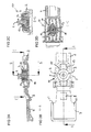
- FIG. 1 shows an assembly 1 comprising a support rail 2, vibration damper 3 and retaining pins 4.
- each four vibration damper 3 and four retaining pins 4 are shown, although in the assembled arrangement 1 according to the illustrated embodiment, only two vibration damper 3 and retaining pins 4 are required.
- the doubling of the illustrated components is solely for the better representation of the vibration damper 3 and retaining pins 4 in different views.
- the support rail 2 comprises contact surfaces 5 which the support rail 2 in the installed state in the vertical direction between in the FIG. 1 Set holding elements not shown a built-in cage of a computer.
- the retaining rail 2 further contact surfaces which define the retaining rail in the installed state in the horizontal direction. These contact surfaces have in the representation of FIG. 1 but down and therefore are not apparent.
- the contact surfaces 5 are arranged on spring elements 6, which cause a shock absorption between the support rail 2 and the installation cage.
- a locking lug 8 is arranged in the region of an end piece 7.
- the locking lug 8 engages in the installed state in an opening of the mounting cage and thus sets the retaining rail 2 in the direction of insertion on the mounting cage.
- the end piece 7 can be easily bent relative to the retaining rail 2 to release the latch to allow removal of a once installed plug-in module.
- the arrangement 1 has a contact spring 9, which produces an electrical contact between a wall of the installation cage and a fixed to the support rail 2 plug-in module.
- the contact spring 9 is made of sheet metal and designed such that it may partially include the support rail 2 and is attachable to this.
- the spring force of the contact spring 9 is designed so that only a negligible transmission of mechanical vibrations by the contact spring 9 is possible.
- the support rail 2 is in the embodiment of a solid plastic material, such as polycarbonate Acrylonitrile-butadiene-styrene (PC / ABS) plastic, and has two first openings 10, which serve to fit the vibration damper 3.
- the first opening 10 comprises two first latching lugs 11, which are arranged in a first direction with respect to the axis of symmetry of the first opening 10, in the insertion direction in the exemplary embodiment.
- the first locking lugs 11 engage in a first circumferential groove 12 of the vibration damper 3.
- the vibration dampers 3 are made of an elastic material such as ethylene-propylene-diene rubber (EPDM) or other suitable elastomer and dampen in particular resonant vibrations, such as occur in the operation of particularly high-speed storage drives such as hard drives or DVD drives.
- the vibration dampers 3 have substantially the shape of a cup or pot, wherein the first circumferential groove 12 is disposed on the outside of the lateral surface directly below a collar.
- the damping of vibrations caused by plug-in modules is particularly important in the case of several storage drives arranged in a common installation cage. Due to the now usual, very high speeds and writing densities, the positioning of writing and reading heads must be done very quickly and accurately. A disturbance of the positioning caused by a vibration leads to a relatively time-consuming readjustment, which increases the access time and reduces the data transmission rate.
- the retaining pins 4 are made of a hard material, such as metal. For example, they may be turned parts which have a pin separated by a collar and a head piece with the second circumferential groove 14. The pins are dimensioned such that they can intervene in particular in usually for screwing plug-in modules imaginary mounting holes.
- the vibration dampers 3 are arranged in the first openings 10 such that the first latching lugs 11 and the second latching lugs 13 are arranged offset in the inserted state by 90 degrees to each other.
- the second locking lugs 13 are arranged in the illustrated embodiment in a vertical direction, that is perpendicular to the insertion direction in which the first locking lugs 11 are arranged. In this way, a direct transmission of vibrations by a pinch of the vibration damper 3 between the first locking lugs 11 and the second locking lug 13 is avoided.
- FIG. 2A shows a first longitudinal section through the arrangement 1 in the region of the end piece 7 and the front first opening 10.
- the first locking lugs 11 engage in this direction in the circumferential groove 12 of the vibration damper 3, in the extension of this line
- an air gap in the second circumferential groove 14 of the retaining pin 4 mechanically decoupled from the support rail 2.
- the collar of the vibration damper 3 rests on the support rail 2, so that the vibration damper 3 can not pass through the support rail 2.
- it is also possible to use the bottom of the first Partially close the opening 10, as in the FIG. 2A is shown.
- FIG. 2B is a plan view of a drawer assembly on the support rail 2 with the end piece 7 arranged thereon.
- the retaining pin 4 is completely isolated mechanically from the retaining rail 2 by the collar of the vibration damper 3.
- the first opening 10 is formed in the region between two further spring elements 15.
- the spring elements 15 further dampen the forces, in particular heavy impacts, between the installation cage and the slide-in module.
- the holding rail 2 facing side of the end piece 7 has two stops 21 which protrude above and below the upper or lower edge of the support rail 2 and set this in the insertion direction. The determination is made below on the basis of FIG. 3 further explained.
- the stops 21 are spatially arranged in the vicinity of the locking lug 8. In this way, a disturbing influence of the different length expansion of the materials involved in heating during operation, for example, a plastic of the support rail 2 and a metal of a mounting cage as far as possible avoided. Also influencing factors other than the temperature, for example one by a high ambient humidity attempted hygroscopic longitudinal expansion, can be avoided in this way.
- FIG. 2C a cross section through the front first opening 10 is shown.
- the engagement of the second locking lugs 13 in the circumferential groove 14 of the retaining pins 4 can be seen.
- Towards the in the Figure 2C illustrated cross section along the axis BB remains an air gap between the support rail 2 and the vibration damper 3 in the region of the second locking lugs 13, so that a mechanical decoupling of the retaining pin 4 is ensured by the support rail 2 in this direction.
- the vibration damper 3 is partially closed at its lower end, so that both a passage of the retaining pin 4 and a direct mechanical contact between the retaining pin 4 and the retaining rail 2 is prevented.
- FIG. 2D shows a second longitudinal section of the arrangement 1 in the region of the first opening 10.
- the second longitudinal section through the first opening 10 along the axis CC shows the spring elements 15 particularly well.
- the first latching lugs 11 and the second latching lugs 13 are offset by 90 degrees relative to one another in order to ensure mechanical decoupling of the retaining pin from the retaining rail 2 in two directions orthogonal to each other and to the axis of symmetry of the retaining pin 4.
- FIG. 3 shows a built-in cage 16 of a computer, not shown, in which a first plug-in module 17 is to be determined by means of two arrangements 1.
- the first drawer assembly 17 is shown in an only partially retracted condition for the interaction of the various elements of the assembly 1 with the mounting cage 16 and the drawer assembly 17.
- a second, in the FIG. 3 predominantly hidden, plug-in module 17 is shown behind the first plug-in module 17 in the fully inserted state.
- the built-in cage 16 has various holding elements 18 which cooperate with the contact surfaces 5 of the arrangement 1. Furthermore, further contact surfaces 19 cooperate with side walls of the installation cage 16.
- the installation cage 16 is made of metal sheets, from which the holding elements 18 are bent out.
- the locking lug 8 in the region of the end piece 7 engages in the inserted state in an opening 20 of the mounting cage 16 a.
- the stops 21 of the end piece 7 fix the retaining rail 2 in the insertion direction, so that the insertion assembly 17 is fixed in the completely inserted state in all spatial directions within the installation cage 16.
- the installation cage 16 out bent stop surfaces 22 above or below the opening 20, which cooperate with the stops 21 in the fully inserted state.
- the installation cage 16 and the support rails 2 have additional means for transport safety. Through them, one or more retaining rails 2 without built-in plug-in modules 17 in the built-in cage 16 are attached so that they are available for later installation of further plug-in modules 17.
- each of the support rails 2 each comprises two tabs 24 which engage in the retracted state behind parts of the front support members 18 to secure them against falling out.
- FIG. 4 shows in each case a front and rear view of a composite arrangement 1.
- the arrangement 1 provides four different functions. First, it allows a screw and tool-free determination of a drawer assembly 17 in a mounting cage 16. For this purpose, the assembled arrangements 1 need only be laterally attached to the plug-in module 17 and inserted together with it in the mounting cage 16.
- the spring elements 6 and 15 as well as the curved contact surfaces 19, which are also designed as spring elements in the exemplary embodiment, provide shock absorption between the installation cage 16 and the plug-in module 17 when installed.
- the vibration dampers 3 effectively suppress self-vibration of the slide-in assembly 17 as well as vibration transmission from adjacent slide-in assemblies 17.
- plug-in modules 17 which are not dependent on a ground connection on the housing, for example because this is provided via a connecting line, can of course be dispensed with the fourth function and thus also on the contact spring 9.
- the other functions and associated features are dispensable, as far as they are not used in a specific arrangement.
Landscapes
- Engineering & Computer Science (AREA)
- Theoretical Computer Science (AREA)
- Computer Hardware Design (AREA)
- General Engineering & Computer Science (AREA)
- Power Engineering (AREA)
- Human Computer Interaction (AREA)
- Physics & Mathematics (AREA)
- General Physics & Mathematics (AREA)
- Connector Housings Or Holding Contact Members (AREA)
- Vibration Prevention Devices (AREA)
- Mounting Of Printed Circuit Boards And The Like (AREA)
- Mounting Components In General For Electric Apparatus (AREA)
Applications Claiming Priority (1)
| Application Number | Priority Date | Filing Date | Title |
|---|---|---|---|
| DE200710024896 DE102007024896B3 (de) | 2007-05-29 | 2007-05-29 | Anordnung und Verfahren zum Festlegen einer Einschubbaugruppe |
Publications (2)
| Publication Number | Publication Date |
|---|---|
| EP2000879A2 true EP2000879A2 (fr) | 2008-12-10 |
| EP2000879A3 EP2000879A3 (fr) | 2011-11-23 |
Family
ID=39099798
Family Applications (1)
| Application Number | Title | Priority Date | Filing Date |
|---|---|---|---|
| EP08100203A Withdrawn EP2000879A3 (fr) | 2007-05-29 | 2008-01-08 | Dispositif et procédé pour la fixation d'un module. |
Country Status (3)
| Country | Link |
|---|---|
| EP (1) | EP2000879A3 (fr) |
| CN (1) | CN101315575B (fr) |
| DE (1) | DE102007024896B3 (fr) |
Families Citing this family (12)
| Publication number | Priority date | Publication date | Assignee | Title |
|---|---|---|---|---|
| US8452148B2 (en) | 2008-08-29 | 2013-05-28 | Corning Cable Systems Llc | Independently translatable modules and fiber optic equipment trays in fiber optic equipment |
| US8712206B2 (en) | 2009-06-19 | 2014-04-29 | Corning Cable Systems Llc | High-density fiber optic modules and module housings and related equipment |
| DE102009033289B4 (de) | 2009-07-06 | 2017-02-09 | Fujitsu Technology Solutions Intellectual Property Gmbh | Anordnung, Halteschiene und Verfahren zum Festlegen einer Einschubbaugruppe |
| DE102010048715B4 (de) | 2010-10-19 | 2012-12-27 | Hilscher Gesellschaft für Systemautomation mbH | Selbstverriegelnde Einschubkontaktanordnung für ein in ein Gerätegehäuse einsetzbares Modul und Modul hierzu |
| DE102010052928B3 (de) | 2010-11-30 | 2012-04-05 | Fujitsu Technology Solutions Intellectual Property Gmbh | Halteschiene für eine Einschubbaugruppe und Anordnung |
| DE102011012661B3 (de) * | 2011-02-28 | 2012-07-26 | Christmann Informationstechnik + Medien Gmbh & Co. Kg | Computereinrichtung und Computerbaugruppe dafür |
| DE102011100179B3 (de) * | 2011-05-02 | 2012-08-16 | Fujitsu Technology Solutions Intellectual Property Gmbh | Halteschiene zur Festlegung einer Computerkomponente in einem Einbaukäfig, Einbaukäfig sowie Verfahren zur Montage und Demontage |
| DE102013107372B9 (de) * | 2013-07-11 | 2015-01-08 | Fujitsu Technology Solutions Intellectual Property Gmbh | Anordnung zum Festlegen einer Einbaukomponente, insbesondere eines Festplattenlaufwerks, in einem Computersystem sowie Halteschiene |
| DE102014110407B4 (de) * | 2014-07-23 | 2017-09-21 | Fujitsu Technology Solutions Intellectual Property Gmbh | Anordnung zum Festlegen einer Einschubbaugruppe sowie Montageverfahren |
| DE102016100237B4 (de) * | 2016-01-08 | 2022-03-31 | Omron Corporation | Speichermediumaufnahmevorrichtung, Industriecomputer und Verfahren |
| DE102017126898B3 (de) * | 2017-11-15 | 2018-11-15 | Fujitsu Technology Solutions Intellectual Property Gmbh | Computersystem mit einem Einbaukäfig |
| DE102018222432A1 (de) * | 2018-12-20 | 2020-06-25 | Robert Bosch Gmbh | Getriebe-Antriebseinheit |
Citations (1)
| Publication number | Priority date | Publication date | Assignee | Title |
|---|---|---|---|---|
| DE10213526A1 (de) | 2002-03-26 | 2003-10-30 | Fujitsu Siemens Computers Gmbh | Festlegung einer Einschubbaugruppe in einem Einbaukäfig eines Computers |
Family Cites Families (10)
| Publication number | Priority date | Publication date | Assignee | Title |
|---|---|---|---|---|
| US4713714A (en) * | 1985-11-26 | 1987-12-15 | Motorola Computer Systems, Inc. | Computer peripheral shock mount for limiting motion-induced errors |
| US5098175A (en) * | 1989-10-27 | 1992-03-24 | International Business Machines Corporation | Removable guide apparatus for a rail-mounted device employed in a computer |
| CN1163809C (zh) * | 2000-07-21 | 2004-08-25 | 富金精密工业(深圳)有限公司 | 数据存储装置的滑轨 |
| US6600648B2 (en) * | 2001-07-10 | 2003-07-29 | Dell Products L.P. | Mounting rail for hard disk drive |
| EP1282347A1 (fr) * | 2001-08-03 | 2003-02-05 | Hewlett-Packard Company, A Delaware Corporation | Boítier pour un sous ensemble d'un ordinateur comprenant un élément de retenu et un élément de support |
| DE10244887B3 (de) * | 2002-09-26 | 2004-06-03 | Fujitsu Siemens Computers Gmbh | Halteschiene zur Festlegung einer Einschub-Baugruppe in einem Einbaukäfig eines Computers |
| CN2636299Y (zh) * | 2003-06-24 | 2004-08-25 | 联想(北京)有限公司 | 硬盘无螺钉减震结构 |
| TWM244556U (en) * | 2003-09-12 | 2004-09-21 | Hon Hai Prec Ind Co Ltd | Mounting apparatus for data storage devices |
| CN1326011C (zh) * | 2004-06-18 | 2007-07-11 | 华硕电脑股份有限公司 | 扣件及电子设备 |
| TWI262375B (en) * | 2004-07-22 | 2006-09-21 | Aopen Inc | Assembling device without the use of tool and host computer case adopting the same |
-
2007
- 2007-05-29 DE DE200710024896 patent/DE102007024896B3/de not_active Expired - Fee Related
-
2008
- 2008-01-08 EP EP08100203A patent/EP2000879A3/fr not_active Withdrawn
- 2008-05-27 CN CN2008100977707A patent/CN101315575B/zh not_active Expired - Fee Related
Patent Citations (1)
| Publication number | Priority date | Publication date | Assignee | Title |
|---|---|---|---|---|
| DE10213526A1 (de) | 2002-03-26 | 2003-10-30 | Fujitsu Siemens Computers Gmbh | Festlegung einer Einschubbaugruppe in einem Einbaukäfig eines Computers |
Also Published As
| Publication number | Publication date |
|---|---|
| DE102007024896B3 (de) | 2008-05-29 |
| CN101315575B (zh) | 2011-10-26 |
| EP2000879A3 (fr) | 2011-11-23 |
| CN101315575A (zh) | 2008-12-03 |
Similar Documents
| Publication | Publication Date | Title |
|---|---|---|
| DE102007024896B3 (de) | Anordnung und Verfahren zum Festlegen einer Einschubbaugruppe | |
| DE19708775C1 (de) | Trägeranordnung für elektronische Baugruppen | |
| EP1403873B1 (fr) | Rail de suspension pour la fixation d'une unité à insérer dans une baie d'ordinateur | |
| DE102009033289B4 (de) | Anordnung, Halteschiene und Verfahren zum Festlegen einer Einschubbaugruppe | |
| DE102013105552B4 (de) | Anordnung zum Festlegen einer Einschubbaugruppe in einem Einbaukäfig eines Computersystems sowie Halteschiene | |
| DE10203390B4 (de) | Einschubrahmen | |
| DE102015122286B3 (de) | Gehäuse für ein Computersystem sowie Computersystem | |
| DE102008049329A1 (de) | Schlosskastengehäuse für Ganzglastüren | |
| DE102020107646A1 (de) | Computer und Verfahren zum Festlegen einer Erweiterungskarte in einem Computer | |
| EP1256955B1 (fr) | Dispositif de fixation d'unité de disques | |
| DE10055455A1 (de) | Befestigungsmittel | |
| EP1772870B1 (fr) | Dispositif destiné à la fixation d'un composant insérable | |
| EP0810541B1 (fr) | Agencement d'un récepteur de cartes dans un appareil à platine | |
| DE102011112368B4 (de) | Komponente zum Einbau in ein Fahrzeug | |
| DE102013113973A1 (de) | Metallischer Halterahmen für einen Steckverbinder | |
| DE102013107372B9 (de) | Anordnung zum Festlegen einer Einbaukomponente, insbesondere eines Festplattenlaufwerks, in einem Computersystem sowie Halteschiene | |
| DE102007004018A1 (de) | Befestigung für eine in einem Ausschnitt einer Einbauwand einsetzbare kastenförmige Aufnahmehalterung | |
| EP1736363B1 (fr) | Structure de montage pour un appareil encastré dans un véhicule | |
| DE102007004021A1 (de) | Befestigung für eine in einem Ausschnitt einer Einbauwand einsetzbare kastenförmige Aufnahmehalterung für Einschubkörper | |
| DE102016106428A1 (de) | Karosseriedeckel eines Kraftfahrzeugs | |
| DE102009051531A1 (de) | Befestigungssystem | |
| DE102014109620B4 (de) | Baugruppenträger für ein Laufwerk und Anordnung mit einem solchen Baugruppenträger und einem Laufwerk | |
| DE102009005088B3 (de) | Anordnung zur Befestigung eines Speicherlaufwerks in einem Computergehäuse und Computersystem mit einem Computergehäuse | |
| DE102017126898B3 (de) | Computersystem mit einem Einbaukäfig | |
| EP1686448B1 (fr) | Cage pour modules |
Legal Events
| Date | Code | Title | Description |
|---|---|---|---|
| PUAI | Public reference made under article 153(3) epc to a published international application that has entered the european phase |
Free format text: ORIGINAL CODE: 0009012 |
|
| AK | Designated contracting states |
Kind code of ref document: A2 Designated state(s): AT BE BG CH CY CZ DE DK EE ES FI FR GB GR HR HU IE IS IT LI LT LU LV MC MT NL NO PL PT RO SE SI SK TR |
|
| AX | Request for extension of the european patent |
Extension state: AL BA MK RS |
|
| RTI1 | Title (correction) |
Free format text: ARRANGEMENT AND METHOD FOR FIXING A MODULE. |
|
| RAP1 | Party data changed (applicant data changed or rights of an application transferred) |
Owner name: FUJITSU TECHNOLOGY SOLUTIONS INTELLECTUAL PROPERTY |
|
| PUAL | Search report despatched |
Free format text: ORIGINAL CODE: 0009013 |
|
| AK | Designated contracting states |
Kind code of ref document: A3 Designated state(s): AT BE BG CH CY CZ DE DK EE ES FI FR GB GR HR HU IE IS IT LI LT LU LV MC MT NL NO PL PT RO SE SI SK TR |
|
| AX | Request for extension of the european patent |
Extension state: AL BA MK RS |
|
| RIC1 | Information provided on ipc code assigned before grant |
Ipc: G06F 1/18 20060101AFI20111020BHEP |
|
| AKY | No designation fees paid | ||
| REG | Reference to a national code |
Ref country code: DE Ref legal event code: R108 |
|
| REG | Reference to a national code |
Ref country code: DE Ref legal event code: R108 Effective date: 20120801 |
|
| STAA | Information on the status of an ep patent application or granted ep patent |
Free format text: STATUS: THE APPLICATION IS DEEMED TO BE WITHDRAWN |
|
| 18D | Application deemed to be withdrawn |
Effective date: 20120524 |