EP2001163B1 - Zugangsvorrichtung und zugangsverfahren für schlitzschnittstelle - Google Patents
Zugangsvorrichtung und zugangsverfahren für schlitzschnittstelle Download PDFInfo
- Publication number
- EP2001163B1 EP2001163B1 EP08156182.1A EP08156182A EP2001163B1 EP 2001163 B1 EP2001163 B1 EP 2001163B1 EP 08156182 A EP08156182 A EP 08156182A EP 2001163 B1 EP2001163 B1 EP 2001163B1
- Authority
- EP
- European Patent Office
- Prior art keywords
- slot
- access device
- interface access
- control module
- master
- Prior art date
- Legal status (The legal status is an assumption and is not a legal conclusion. Google has not performed a legal analysis and makes no representation as to the accuracy of the status listed.)
- Active
Links
Images


Classifications
-
- H—ELECTRICITY
- H04—ELECTRIC COMMUNICATION TECHNIQUE
- H04L—TRANSMISSION OF DIGITAL INFORMATION, e.g. TELEGRAPHIC COMMUNICATION
- H04L69/00—Network arrangements, protocols or services independent of the application payload and not provided for in the other groups of this subclass
- H04L69/40—Network arrangements, protocols or services independent of the application payload and not provided for in the other groups of this subclass for recovering from a failure of a protocol instance or entity, e.g. service redundancy protocols, protocol state redundancy or protocol service redirection
-
- H—ELECTRICITY
- H04—ELECTRIC COMMUNICATION TECHNIQUE
- H04L—TRANSMISSION OF DIGITAL INFORMATION, e.g. TELEGRAPHIC COMMUNICATION
- H04L41/00—Arrangements for maintenance, administration or management of data switching networks, e.g. of packet switching networks
-
- H—ELECTRICITY
- H04—ELECTRIC COMMUNICATION TECHNIQUE
- H04L—TRANSMISSION OF DIGITAL INFORMATION, e.g. TELEGRAPHIC COMMUNICATION
- H04L41/00—Arrangements for maintenance, administration or management of data switching networks, e.g. of packet switching networks
- H04L41/40—Arrangements for maintenance, administration or management of data switching networks, e.g. of packet switching networks using virtualisation of network functions or resources, e.g. SDN or NFV entities
-
- H—ELECTRICITY
- H04—ELECTRIC COMMUNICATION TECHNIQUE
- H04L—TRANSMISSION OF DIGITAL INFORMATION, e.g. TELEGRAPHIC COMMUNICATION
- H04L61/00—Network arrangements, protocols or services for addressing or naming
- H04L61/09—Mapping addresses
- H04L61/25—Mapping addresses of the same type
-
- H—ELECTRICITY
- H04—ELECTRIC COMMUNICATION TECHNIQUE
- H04Q—SELECTING
- H04Q2213/00—Indexing scheme relating to selecting arrangements in general and for multiplex systems
- H04Q2213/13003—Constructional details of switching devices
-
- H—ELECTRICITY
- H04—ELECTRIC COMMUNICATION TECHNIQUE
- H04Q—SELECTING
- H04Q2213/00—Indexing scheme relating to selecting arrangements in general and for multiplex systems
- H04Q2213/13091—CLI, identification of calling line
-
- H—ELECTRICITY
- H04—ELECTRIC COMMUNICATION TECHNIQUE
- H04Q—SELECTING
- H04Q2213/00—Indexing scheme relating to selecting arrangements in general and for multiplex systems
- H04Q2213/13097—Numbering, addressing
-
- H—ELECTRICITY
- H04—ELECTRIC COMMUNICATION TECHNIQUE
- H04Q—SELECTING
- H04Q2213/00—Indexing scheme relating to selecting arrangements in general and for multiplex systems
- H04Q2213/13164—Traffic (registration, measurement,...)
-
- H—ELECTRICITY
- H04—ELECTRIC COMMUNICATION TECHNIQUE
- H04Q—SELECTING
- H04Q2213/00—Indexing scheme relating to selecting arrangements in general and for multiplex systems
- H04Q2213/13166—Fault prevention
-
- H—ELECTRICITY
- H04—ELECTRIC COMMUNICATION TECHNIQUE
- H04Q—SELECTING
- H04Q2213/00—Indexing scheme relating to selecting arrangements in general and for multiplex systems
- H04Q2213/13167—Redundant apparatus
-
- H—ELECTRICITY
- H04—ELECTRIC COMMUNICATION TECHNIQUE
- H04Q—SELECTING
- H04Q2213/00—Indexing scheme relating to selecting arrangements in general and for multiplex systems
- H04Q2213/13399—Virtual channel/circuits
Definitions
- the present invention relates to a slot interface access device and a slot interface access device assembly for accessing slot interfaces present to be distributed in a plurality of main devices, and a method and a program therefor.
- the "main device” means herein a device that includes an interface for accommodating a terminal (e.g., a button telephone), an interface connecting the main device to a public line, and an interface connecting the main device to an IP network.
- a terminal e.g., a button telephone
- the systems manage slots for packages that are resources of each main device separately. Due to this, each system is unable to know information, states, and the like of resources of the other systems. As a result, restrictions are imposed on use of functions of the other main devices on the network.
- An object of a reference embodiment to be described below is to construct a networking system architecture that can facilitate managing information and that is free from restrictions to functions by allowing one main device to integrally manage information such as resources of hardware of all main devices connected to one another by a network.
- the gist of the reference embodiment lies in a technique for allowing each main device to handle resources on the network as if they are its own resources.
- hardware resource management that is, management of terminals, lines and the like is made in the form of package management.
- Fig. 1 is a conceptual diagram of package management on the network.
- a package is installed into a main device 2, information on the package and information on a terminal, a line and the like connected to the package are transmitted to a main device 1 via the Ethernet (registered trademark).
- a lower layer of the main device 1 processes the downstream data and transmits a command to a virtual package to a real package on the network.
- each main device can handle resources on the network as if they are its own resources.
- each main device such as the call control unit can freely use resources without knowledge that the resources are present on the network.
- Fig. 2 is a configuration diagram of the networking system architecture according to the reference embodiment.
- a main device managing all the resources on the network and exerting all call controls is referred to as "master”.
- a main device connected to the master, providing package information to the master, and obeying commands from the master is referred to as "slave”.
- the master can control a plurality of slaves and can handle resources of the main devices connected to the master as slaves as if they are all its own resources.
- the networking system architecture constituted by the master and the slaves can thereby act as if it is one system.
- the main device set as the master awaits connection from the slaves and each of the slaves establishes connection to a preset IP address of the mater.
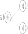
- Fig. 3 shows a system configuration on the networking system architecture.
- the systems are given unique system IDs, respectively.
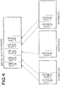
- Fig. 4 is a conceptual diagram of slot management according to the reference embodiment.
- Packages are physically installed into slots of each of the systems connected to the network and having the systems ID, respectively. Information on the packages is unitarily integrated into a virtual slot database and the master (system) manages the virtual slot database.
- the master controls slots while referring to this virtual slot database.
- slots belong to the system other than the master, the slots are present physically at a remote location connected to the master by an IP network. However, the master can handle the slots as if they are its own slots without knowledge that the physical slots are at remote locations.
- the master can handle terminals and lines connected to the packages installed into the slots as if they are terminals and lines connected to the master.
- Fig. 5 shows the systems representing the above-stated manners.
- Packages connecting terminals, packages accommodating therein lines connected to a public line, and packages accommodating therein IP lines connected to the IP network are installed into a system having system ID: 1, a system having system ID: 2, and a system having system ID: 3, respectively.
- each of the systems can freely control the terminals, lines and the like accommodated in the packages connected to the slots as if they are its own terminals, lines and the like.
- the systems shown in Fig. 5 are built on a client-server architecture in which one master controls slaves.
- the master performs call processings on all the main devices including the master and manages a database.
- the master also manages virtual slots.
- IP internet protocol
- the systems 1, 2, and 3 include packages accommodating therein terminals, packages accommodating therein ordinary lines, and packages accommodating therein IP lines, respectively.
- the virtual slot database manages information on these packages. While the master basically manages the data, each of the slaves holds the same data in case of replacement of the master.
- Fig. 6 shows data flow for conventional package control.
- upstream data from a package is transmitted from a slot I/F module 101 to a CAPS (call control module)/OPMS (package and terminal management module) 105 via an IOCS (input/output control module) 103.
- CAPS call control module
- OPMS packet and terminal management module
- IOCS input/output control module
- the CAPS/OPMS 105 processes the upstream data and transmits a downstream command to the slot I/F module 101 via the IOCS 103. For example, if a package is installed into a slot, then data is transmitted to the CAPS/OMPS 105 as upstream data, and the CAPS/OMPS 105 recognizes package installation and exercises a starting control over the package, i.e., permits the package to be active. If a terminal connected to the package installed into the slot is off the hook, the slot I/F module 101 transmits data indicating that the terminal is off the hook to the CAPS/OPMS 105 as upstream data. In response to the upstream data, the CAPS/OPMS 105 transmits a command to produce a dial tone from the terminal to the slot I/F 101 via the IOCS 103 as downstream data.
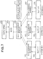
- Fig. 7 shows data flow according to the reference embodiment.
- slot management by networking is realized by additionally providing slot control modules 107 each controlling slot input/output and a slot management module 109 managing slot information.
- Upstream data from one slot is subjected to a temporary spooling by one of the slot control modules 107 corresponding to a system including the slot and then transmitted to the slot management module 109 of the master controlling the system. If the system is the master, the upstream data is transmitted to its own slot management module 109.
- the slot management module 109 exercises such a control that it appears to the IOCS 103 that is a higher module that the data transmitted to the slot management module 109 is transmitted from a certain slot.
- the slot management module 109 receives data from a specific slot of a certain system and the specific slot is a slot of the system that has not been recognized so far, the slot management module 109 newly assigns a virtual slot number to the slot and subsequently regards the slot of the system as the slot to which the virtual slot number is assigned.
- a virtual slot number 1 is assigned to the slot 1.
- the higher module such as the IOCS 103 or the CAPS/OPMS 105 regards the data transmitted from the slot 1 of the system 1 as data from its own slot 1 even without knowledge of the network.
- downstream data is to be actually transmitted to a slot to issue a command to hardware, the command is issued to a slot of an appropriate system while referring to the physical slot/virtual slot contrast table 111.
- the command is transmitted to the slot control modules 107 of the systems and commands are transmitted to actual packages of the systems, respectively.
- processings are performed using virtual slot numbers.
- parts visible to a user such as setting of system data, it is often desired to perform a processing while identifying by which slot in which system the processing is performed.
- settings and the like can be made using physical slots while referring to the physical slot/virtual slot contrast table 111.
- the reference embodiment solves many of the conventional problems by attaining the central control networking system architecture so as to avoid problems with a distributed networking system architecture.
- PCs personal computers
- a slot interface access device comprising: a slot management module; a slot control module; and a physical slot to management slot contrast table, wherein the slot management module, the slot control module, and the physical slot to management slot contrast table are provided between an input and output control module and a slot interface lower than the input and output control module, the input and output control module accesses the slot interface using virtual slot identification information, the slot management module converts the virtual slot identification information into physical slot identification information while referring to the physical slot to management slot contrast table, and accesses the slot control module corresponding to the physical slot identification information, thereby realizing a physical access of the input and output control module to the slot interface, and the slot interface access device is higher in CPU capability than other devices each including the slot interface.
- the slot interface access device may be configured not to comprise the slot interface.
- a slot interface access device assembly comprising: the slot interface access device according to the first aspect; and a slot interface access device acting as a substitute for the slot interface access device according to the first aspect if the slot interface access device according to the first aspect malfunctions, and having a higher CPU capability than CPU capabilities of the other devices.
- a system including a high performance CPU can be used to act as a master main device and a larger-scale networking system architecture can be constructed.
- not a switchboard but a high performance general-purpose PC is used as a system that acts as a master main device, thereby avoiding the conventional problems.
- a similar program to the switchboard is allowed to be executed on the PC and a plurality of main devices is connected to the PC by an IP network.
- the PC acting as the master main device controls hardware of the main devices connected to the PC as slave main devices.
- a high performance CPU included in the PC can be used, so that the PC can handle heavy traffic from the slave main devices.
- Fig. 9 is a conceptual diagram of a resource central control networking system architecture in which the PC acts as the master main device.
- Fig. 9 represents that the PC acts as the master main device and controls real main devices acting as slave main devices.
- the PC is naturally incapable of directly controlling hardware of a switchboard, so that the slave main devise connected to the switchboard control the hardware, respectively.
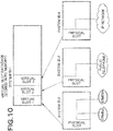
- a package management method shown in Fig. 10 is an applied method of that according to the reference embodiment.
- Packages that are real hardware are installed into the slave main devise identified by system IDs: 2, 3, and 4, respectively.
- the slave main devices are also referred to as “systems 2, 3, and 4", respectively, hereinafter. All information on the packages is transmitted to and managed by the master main device identified by system ID 1.
- the master main device is also referred to as "system 1", hereinafter.
- a command to a real package is transferred to each of the packages of the systems 2, 3, and 4 so as to control the terminals, the lines and the like connected to the systems 2, 3, and 4, respectively.
- the resource central control networking system architecture introduces a mechanism for selecting a substitute master main device so as to continue operation if the master main device goes down or communication breaks down for some reason.
- a mechanism shown in Fig. 9 if the PC acting as the master main device goes down, one of the main devices that is connected to the PC as the slave main device and that has a highest master main device priority is selected from among those connected to the PC as the slave main devices since the PC is not connected to the network. As a result, the node having low CPU capability acts as a new or substitute master main device.
- the resource central control networking system architecture introduces a mechanism for putting a PC acting as a substitute mater main device on standby as a backup PC and for causing the backup PC to operate during occurrence of a failure.
- Fig. 11 is a conceptual diagram showing the resource central control networking system architecture in which a first PC acts as the master main device and a second PC acts as a substitute master main device.
- Fig. 11 shows that the second PC newly participates in the network shown in Fig. 9 as a slave main device.
- system 5 While the system 1 acting as the master main device operates normally, the PC identified by a system ID 5 (hereinafter, also "system 5") does not operate but is on standby. If a failure occurs to the system 1, the system 5 detects the occurrence of a failure and starts operating as the substitute master main device. By doing so, as shown in Fig. 12 , even if a failure occurs to the PC acting as the master main device, the second PC having a similar CPU performance to that of the master main device can succeed to functions of the master main device. It is thereby possible to prevent deterioration in traffic processing capability. Furthermore, as shown in Fig. 13 , if the system 1 returns from the failure, the system 1 is connected to the system 5 as a slave main device and put on standby in case of a failure. If a failure occurs to the system 5, the system 1 is allowed to start operating again as the master main device.
- system ID 5 hereinafter, also "system 5”
- the active device acts as the master main device and the network can continue to operate.
- the systems 2, 3, and 4 are real main devices including slots into which packages are installed, and accommodate therein packages connected to terminals, a public line, and an IP network, respectively.
- the systems 2, 3, and 4 which operate as the slave main devices, respectively, are connected to the first PC or the system 1 acting as the master main device by the IP, and are controlled by the system 1.
- the first PC or the system 1 acting as the master main device integrally manages information such as hardware information and call states of the packages accommodated in the systems 2, 3, and 4, and exercises call control over all the systems 2, 3, and 4 (slave main devices) connected to the first PC.
- the system 5 which is connected to the system 1 as the slave main device, monitors the system 1 and is put on standby in case of a failure.
- a method related to package resource management is the same as that described in the reference embodiment.
- Fig. 14 is a conceptual diagram of a networking system architecture in which a real main device acts as a master main device according to a conventional technique.
- Functional modules of the networking system architecture are roughly classified into a call control unit controlling incoming calls and conversation, communication units each transmitting or receiving package data between the master main device and the slave main device, and hardware control units each receiving data from a package and transmitting a command to a package.
- the hardware control unit receives data from a package, and the communication unit transmits the data to the master main device.
- the call control unit exerts call control based on the data transmitted from one of the slave main devices, and the communication unit transmits package data to the slave main device.
- the slave main device receives the package data and controls the hardware.
- the hardware control unit operates to control packages.
- Fig. 15 is a conceptual diagram of functional modules according to the embodiment of the present invention.
- the master main device is the general-purpose PC, the master main device is naturally incapable of directly accommodating therein packages. Therefore, there is no need to provide a hardware control unit in the master main device.
- the hardware control unit if the hardware control unit is present, the unit intends to control hardware that is not actually present. Due to this, it is necessary to prohibit the hardware control unit from operating.
- a call control unit and a communication unit are modules to be mounted in the master main device as shown in Fig. 15 . It is, therefore, possible to mount the call control unit and the communication unit in the PC without depending on a processing target.
- a built-in OS such as Linux (registered trademark) can be mounted in the PC whereas a built-in OS such as VxWorks (registered trademark) or Nucleus Plus can be mounted in each real main device.
- the resource central control networking system architecture includes the function of selecting one slave main device having the highest master main device priority set in advance as a substitute master main device from among the slave main devices so as to continue network operation if the master main device goes down.
- the real main device including only a low performance CPU and a small capacity memory from being selected as the substitute master main device, it is necessary to give low master main device priorities to the real main devices and give a highest master main device priority to the second or backup PC.
Landscapes
- Engineering & Computer Science (AREA)
- Computer Networks & Wireless Communication (AREA)
- Signal Processing (AREA)
- Computer Security & Cryptography (AREA)
- Data Exchanges In Wide-Area Networks (AREA)
- Communication Control (AREA)
Claims (3)
- Netzsystem mit einer ersten Schlitzschnittstellenzugangsvorrichtung, einer zweiten Schlitzschnittstellenzugangsvorrichtung und einer anderen Schlitzschnittstellenzugangsvorrichtung, die jeweils einen physikalischen Schlitz, eine Schlitzschnittstelle und ein Schlitzsteuermodul (107) aufweisen,
wobei die erste Schlitzschnittstellenzugangsvorrichtung und die zweite Schlitzschnittstellenzugangsvorrichtung jeweils Folgendes aufweisen:ein Eingangs- und Ausgangssteuermodul (103),ein Schlitzverwaltungsmodul (109) undeine Physikalischer-Schlitz-zu-virtueller-Schlitz-Kontrasttabelle (111),wobei das Schlitzverwaltungsmodul (109), das Schlitzsteuermodul (107) und die Physikalischer-Schlitz-zuvirtueller-Schlitz-Kontrasttabelle (111) zwischen dem Eingangs- und Ausgangssteuermodul (103) und der Schlitzschnittstelle (101), die sich in einer Schicht unterhalb einer Schicht befindet, in der sich das Eingangs- und Ausgangssteuermodul (103) befindet, bereitgestellt sind,das Eingangs- und Ausgangssteuermodul (103) dafür eingerichtet ist, unter Verwendung von virtuellen Schlitz-Identifikationsinformationen auf die Schlitzschnittstelle der anderen Schlitzschnittstellenzugangsvorrichtung zuzugreifen,das Schlitzverwaltungsmodul (109) dafür eingerichtet ist, die virtuellen Schlitz-Identifikationsinformationen unter Bezugnahme auf die Physikalischer-Schlitz-zuvirtueller-Schlitz-Kontrasttabelle (111) in physikalische Schlitz-Identifikationsinformationen umzuwandeln und entsprechend den Physikalischer-Schlitz-Identifikationsinformationen auf das Schlitzsteuermodul der anderen Schlitzschnittstellenzugangsvorrichtung zuzugreifen, wodurch ein physikalischer Zugriff des Eingangs- und Ausgangssteuermoduls (103) auf die Schlitzschnittstelle der anderen Schlitzschnittstellenzugangsvorrichtung verwirklicht wird, undwobei die zweite Schlitzschnittstellenzugangsvorrichtung als ein Ersatz für die erste Schlitzschnittstellenzugangsvorrichtung wirkt, falls eine Fehlfunktion in der ersten Schlitzschnittstellenzugangsvorrichtung auftritt, und eine höhere CPU-Kapazität aufweist als die andere Schlitzschnittstellenzugangsvorrichtung. - Schlitzschnittstellenzugangsverfahren für ein Netzsystem mit einer ersten Schlitzschnittstellenzugangsvorrichtung, einer zweiten Schlitzschnittstellenzugangsvorrichtung und einer anderen Schlitzschnittstellenzugangsvorrichtung, die jeweils einen physikalischen Schlitz, eine Schlitzschnittstelle und ein Schlitzsteuermodul (107) aufweisen,
wobei die erste Schlitzschnittstellenzugangsvorrichtung und die zweite Schlitzschnittstellenzugangsvorrichtung jeweils ein Eingangs- und Ausgangssteuermodul (103), ein Schlitzverwaltungsmodul (109) und eine Physikalischer-Schlitz-zu-virtueller-Schlitz-Kontrasttabelle (111) aufweisen, wobei das Schlitzverwaltungsmodul (109), das Schlitzsteuermodul (107) und die Physikalischer-Schlitz-zuvirtueller-Schlitz-Kontrasttabelle (111) zwischen dem Eingangs- und Ausgangssteuermodul (103) und der Schlitzschnittstelle (101), die sich in einer Schicht unterhalb der Schicht befindet, in der sich das Eingangs- und Ausgangssteuermodul (103) befindet, bereitgestellt sind, und
wobei das Schlitzschnittstellenzugangsverfahren Folgendes aufweist:erstens Bewirken, dass das Eingangs- und Ausgangssteuermodul (103) der ersten Schlitzschnittstellenzugangsvorrichtung auf die Schlitzschnittstelle (101) der anderen Schlitzschnittstellenzugangsvorrichtung unter Verwendung virtueller Schlitz-Identifikationsinformationen zugreift undzweitens Bewirken, dass das Schlitzverwaltungsmodul (109) der ersten Schlitzschnittstellenzugangsvorrichtung die virtuellen Schlitz-Identifikationsinformationen unter Bezugnahme auf die Physikalischer-Schlitz-zu-virtueller-Schlitz-Kontrasttabelle (111) in physikalische Schlitz-Identifikationsinformationen umwandelt, und entsprechend den physikalischen Schlitz-Identifikationsinformationen auf das Schlitzsteuermodul (107) der anderen Schlitzschnittstellenzugangsvorrichtung zugreift, um dadurch einen physikalischen Zugriff des Eingangs- und Ausgangssteuermoduls (103) auf die Schlitzschnittstelle der anderen Schlitzschnittstellenzugangsvorrichtung zu bewirken, unddrittens Bewirken, dass die zweite Schlitzschnittstellenzugangsvorrichtung, die eine höhere CPU-Kapazität aufweist als die anderen Schlitzschnittstellenzugangsvorrichtungen, als ein Ersatz für die erste Schlitzschnittstellenzugangsvorrichtung wirkt, welche den ersten und den zweiten Vorgang ausführt, falls die erste Schlitzschnittstellenzugangsvorrichtung, welche den ersten und den zweiten Vorgang ausführt, eine Fehlfunktion aufweist. - Computerprogrammprodukt, das auf einem computerlesbaren Medium verwirklicht ist und Codes aufweist, die, wenn sie ausgeführt werden, Computer veranlassen, als in Anspruch 1 definierte erste Schlitzschnittstellenzugangsvorrichtung und zweite Schnittstellenzugangsvorrichtung zu wirken.
Applications Claiming Priority (1)
| Application Number | Priority Date | Filing Date | Title |
|---|---|---|---|
| JP2007133960 | 2007-05-21 |
Publications (3)
| Publication Number | Publication Date |
|---|---|
| EP2001163A2 EP2001163A2 (de) | 2008-12-10 |
| EP2001163A3 EP2001163A3 (de) | 2008-12-17 |
| EP2001163B1 true EP2001163B1 (de) | 2017-11-15 |
Family
ID=39870161
Family Applications (1)
| Application Number | Title | Priority Date | Filing Date |
|---|---|---|---|
| EP08156182.1A Active EP2001163B1 (de) | 2007-05-21 | 2008-05-14 | Zugangsvorrichtung und zugangsverfahren für schlitzschnittstelle |
Country Status (4)
| Country | Link |
|---|---|
| US (1) | US7761639B2 (de) |
| EP (1) | EP2001163B1 (de) |
| AU (1) | AU2008201943B2 (de) |
| CA (1) | CA2630125C (de) |
Families Citing this family (1)
| Publication number | Priority date | Publication date | Assignee | Title |
|---|---|---|---|---|
| CN103246634B (zh) * | 2013-04-26 | 2017-02-08 | 华为技术有限公司 | 一种对多处理器系统进行工作模式配置的方法和装置 |
Family Cites Families (17)
| Publication number | Priority date | Publication date | Assignee | Title |
|---|---|---|---|---|
| JPH1041956A (ja) | 1996-07-25 | 1998-02-13 | Nec Corp | Atm構内交換機の回線容量制御システム |
| JP3800378B2 (ja) | 1997-12-15 | 2006-07-26 | Necインフロンティア株式会社 | Cti機能を有するパソコン |
| US6418493B1 (en) * | 1997-12-29 | 2002-07-09 | Intel Corporation | Method and apparatus for robust addressing on a dynamically configurable bus |
| US6243774B1 (en) * | 1998-06-30 | 2001-06-05 | International Business Machines Corporation | Apparatus program product and method of managing computer resources supporting concurrent maintenance operations |
| US6427176B1 (en) * | 1999-03-04 | 2002-07-30 | International Business Machines Corporation | Method and apparatus for maintaining system labeling based on stored configuration labeling information |
| JP3451982B2 (ja) | 1999-05-14 | 2003-09-29 | 日本電気株式会社 | 分散アクセス方式とその方法 |
| JP2001358736A (ja) | 2000-06-15 | 2001-12-26 | Mitsubishi Electric Corp | リング型ネットワークシステム |
| US6782464B2 (en) * | 2001-07-17 | 2004-08-24 | International Business Machines Corporation | Mapping a logical address to a plurality on non-logical addresses |
| US6968398B2 (en) * | 2001-08-15 | 2005-11-22 | International Business Machines Corporation | Method of virtualizing I/O resources in a computer system |
| JP2003345407A (ja) | 2002-05-30 | 2003-12-05 | Meidensha Corp | 二重化plc間のデータ等価方式 |
| US7636364B2 (en) * | 2002-10-31 | 2009-12-22 | Force 10 Networks, Inc. | Redundant router network |
| US7146497B2 (en) * | 2003-09-30 | 2006-12-05 | International Business Machines Corporation | Scalability management module for dynamic node configuration |
| JP4227917B2 (ja) | 2004-03-16 | 2009-02-18 | Necインフロンティア株式会社 | Ctiシステム |
| US7516252B2 (en) * | 2005-06-08 | 2009-04-07 | Intel Corporation | Port binding scheme to create virtual host bus adapter in a virtualized multi-operating system platform environment |
| CN100454266C (zh) * | 2005-10-26 | 2009-01-21 | 鸿富锦精密工业(深圳)有限公司 | 电脑组件组装位置正确性验证的方法 |
| US7363404B2 (en) * | 2005-10-27 | 2008-04-22 | International Business Machines Corporation | Creation and management of destination ID routing structures in multi-host PCI topologies |
| US7836238B2 (en) * | 2006-12-19 | 2010-11-16 | International Business Machines Corporation | Hot-plug/remove of a new component in a running PCIe fabric |
-
2008
- 2008-04-25 CA CA2630125A patent/CA2630125C/en active Active
- 2008-05-01 AU AU2008201943A patent/AU2008201943B2/en active Active
- 2008-05-12 US US12/118,977 patent/US7761639B2/en active Active
- 2008-05-14 EP EP08156182.1A patent/EP2001163B1/de active Active
Non-Patent Citations (1)
| Title |
|---|
| None * |
Also Published As
| Publication number | Publication date |
|---|---|
| CA2630125C (en) | 2013-06-18 |
| AU2008201943A1 (en) | 2008-12-11 |
| EP2001163A3 (de) | 2008-12-17 |
| US7761639B2 (en) | 2010-07-20 |
| AU2008201943B2 (en) | 2013-03-28 |
| CA2630125A1 (en) | 2008-11-21 |
| EP2001163A2 (de) | 2008-12-10 |
| US20080294827A1 (en) | 2008-11-27 |
Similar Documents
| Publication | Publication Date | Title |
|---|---|---|
| EP2003814B1 (de) | Zugangsvorrichtung, Zugangsverfahren und Programm für Schlitzschnittstelle | |
| EP1993232B1 (de) | Redundanzeinstellung und Austauschverfahren für ein Hauptgerät | |
| JP5366177B2 (ja) | スロットインターフェースアクセス装置、その方法及びそのプログラム並びに主装置の冗長構成及び代替方法 | |
| US8285905B2 (en) | Redundancy configuration and replacement method in a system including a master main unit and slave main units | |
| JP2009118063A (ja) | 冗長システム、方法及びプログラム、並びに、サーバ | |
| EP2001163B1 (de) | Zugangsvorrichtung und zugangsverfahren für schlitzschnittstelle | |
| CN101036377B (zh) | 分布式通信系统、处理装置和接入点 | |
| JP3913608B2 (ja) | 全ての知的タイプなモジュールが同一の使用者入出力インターフェースを共用できる知的タイプな装置 | |
| KR20050067413A (ko) | 서비스 통합 시스템을 위한 방법 및 장치 | |
| EP3886370B1 (de) | Kommunikationssystem und kommunikationsvorrichtung | |
| JP2002354049A (ja) | 回線管理システム | |
| CA2643001C (en) | Slot interface access unit, method thereof, and program thereof, as well as redundancy configuration of main unit, and replacing method of the same | |
| KR20170131028A (ko) | 공용망의 서버를 통한 사설망 클라이언트 관리시스템 및 이를 이용한 관리방법 | |
| JP5196547B2 (ja) | 主装置、該主装置への多機能ユニットの実装方法及びそのプログラム | |
| JP6084366B2 (ja) | 冗長化構築システム及び冗長化構築プログラム |
Legal Events
| Date | Code | Title | Description |
|---|---|---|---|
| PUAI | Public reference made under article 153(3) epc to a published international application that has entered the european phase |
Free format text: ORIGINAL CODE: 0009012 |
|
| PUAL | Search report despatched |
Free format text: ORIGINAL CODE: 0009013 |
|
| AK | Designated contracting states |
Kind code of ref document: A2 Designated state(s): AT BE BG CH CY CZ DE DK EE ES FI FR GB GR HR HU IE IS IT LI LT LU LV MC MT NL NO PL PT RO SE SI SK TR |
|
| AX | Request for extension of the european patent |
Extension state: AL BA MK RS |
|
| AK | Designated contracting states |
Kind code of ref document: A3 Designated state(s): AT BE BG CH CY CZ DE DK EE ES FI FR GB GR HR HU IE IS IT LI LT LU LV MC MT NL NO PL PT RO SE SI SK TR |
|
| AX | Request for extension of the european patent |
Extension state: AL BA MK RS |
|
| 17P | Request for examination filed |
Effective date: 20090617 |
|
| AKX | Designation fees paid |
Designated state(s): DE GB |
|
| RAP1 | Party data changed (applicant data changed or rights of an application transferred) |
Owner name: NEC PLATFORMS, LTD. |
|
| 17Q | First examination report despatched |
Effective date: 20161201 |
|
| GRAP | Despatch of communication of intention to grant a patent |
Free format text: ORIGINAL CODE: EPIDOSNIGR1 |
|
| INTG | Intention to grant announced |
Effective date: 20170707 |
|
| GRAS | Grant fee paid |
Free format text: ORIGINAL CODE: EPIDOSNIGR3 |
|
| GRAA | (expected) grant |
Free format text: ORIGINAL CODE: 0009210 |
|
| AK | Designated contracting states |
Kind code of ref document: B1 Designated state(s): DE GB |
|
| REG | Reference to a national code |
Ref country code: GB Ref legal event code: FG4D |
|
| REG | Reference to a national code |
Ref country code: DE Ref legal event code: R096 Ref document number: 602008052944 Country of ref document: DE |
|
| REG | Reference to a national code |
Ref country code: DE Ref legal event code: R097 Ref document number: 602008052944 Country of ref document: DE |
|
| PLBE | No opposition filed within time limit |
Free format text: ORIGINAL CODE: 0009261 |
|
| STAA | Information on the status of an ep patent application or granted ep patent |
Free format text: STATUS: NO OPPOSITION FILED WITHIN TIME LIMIT |
|
| 26N | No opposition filed |
Effective date: 20180817 |
|
| REG | Reference to a national code |
Ref country code: DE Ref legal event code: R079 Ref document number: 602008052944 Country of ref document: DE Free format text: PREVIOUS MAIN CLASS: H04L0012240000 Ipc: H04L0041000000 |
|
| PGFP | Annual fee paid to national office [announced via postgrant information from national office to epo] |
Ref country code: DE Payment date: 20250521 Year of fee payment: 18 |
|
| PGFP | Annual fee paid to national office [announced via postgrant information from national office to epo] |
Ref country code: GB Payment date: 20250530 Year of fee payment: 18 |