EP2001410B1 - Implant prothétique et son procédé d'assemblage - Google Patents
Implant prothétique et son procédé d'assemblage Download PDFInfo
- Publication number
- EP2001410B1 EP2001410B1 EP07759077.6A EP07759077A EP2001410B1 EP 2001410 B1 EP2001410 B1 EP 2001410B1 EP 07759077 A EP07759077 A EP 07759077A EP 2001410 B1 EP2001410 B1 EP 2001410B1
- Authority
- EP
- European Patent Office
- Prior art keywords
- insert
- head
- cavity
- connector
- polymeric
- Prior art date
- Legal status (The legal status is an assumption and is not a legal conclusion. Google has not performed a legal analysis and makes no representation as to the accuracy of the status listed.)
- Not-in-force
Links
- 239000007943 implant Substances 0.000 title claims description 67
- 238000000034 method Methods 0.000 title claims description 12
- 239000000463 material Substances 0.000 claims description 33
- OKTJSMMVPCPJKN-UHFFFAOYSA-N Carbon Chemical compound [C] OKTJSMMVPCPJKN-UHFFFAOYSA-N 0.000 claims description 32
- 229910002804 graphite Inorganic materials 0.000 claims description 29
- 239000010439 graphite Substances 0.000 claims description 29
- 210000000988 bone and bone Anatomy 0.000 claims description 17
- 229910001092 metal group alloy Inorganic materials 0.000 claims description 14
- 239000011248 coating agent Substances 0.000 claims description 13
- 238000000576 coating method Methods 0.000 claims description 13
- 239000000758 substrate Substances 0.000 claims description 13
- 229910052751 metal Inorganic materials 0.000 claims description 12
- 239000002184 metal Substances 0.000 claims description 12
- 230000013011 mating Effects 0.000 claims description 10
- 239000002178 crystalline material Substances 0.000 claims description 6
- 238000002513 implantation Methods 0.000 claims description 6
- 230000005489 elastic deformation Effects 0.000 claims description 4
- 238000003780 insertion Methods 0.000 claims description 4
- 230000037431 insertion Effects 0.000 claims description 4
- 230000001419 dependent effect Effects 0.000 claims 4
- 239000004699 Ultra-high molecular weight polyethylene Substances 0.000 description 5
- 239000002131 composite material Substances 0.000 description 5
- 229920003023 plastic Polymers 0.000 description 5
- 239000004033 plastic Substances 0.000 description 5
- 229920000785 ultra high molecular weight polyethylene Polymers 0.000 description 5
- 241000131317 Capitulum Species 0.000 description 4
- 238000010276 construction Methods 0.000 description 4
- 210000000623 ulna Anatomy 0.000 description 4
- 230000008901 benefit Effects 0.000 description 3
- 229910052799 carbon Inorganic materials 0.000 description 3
- 239000000919 ceramic Substances 0.000 description 3
- 210000003041 ligament Anatomy 0.000 description 3
- 230000000399 orthopedic effect Effects 0.000 description 3
- 230000002093 peripheral effect Effects 0.000 description 3
- 230000000704 physical effect Effects 0.000 description 3
- 229920000642 polymer Polymers 0.000 description 3
- MCMNRKCIXSYSNV-UHFFFAOYSA-N Zirconium dioxide Chemical compound O=[Zr]=O MCMNRKCIXSYSNV-UHFFFAOYSA-N 0.000 description 2
- 230000008859 change Effects 0.000 description 2
- 210000004439 collateral ligament Anatomy 0.000 description 2
- 210000002758 humerus Anatomy 0.000 description 2
- 229910001182 Mo alloy Inorganic materials 0.000 description 1
- 206010061307 Neck deformity Diseases 0.000 description 1
- RTAQQCXQSZGOHL-UHFFFAOYSA-N Titanium Chemical compound [Ti] RTAQQCXQSZGOHL-UHFFFAOYSA-N 0.000 description 1
- 229920010741 Ultra High Molecular Weight Polyethylene (UHMWPE) Polymers 0.000 description 1
- 241001227561 Valgus Species 0.000 description 1
- PNEYBMLMFCGWSK-UHFFFAOYSA-N aluminium oxide Inorganic materials [O-2].[O-2].[O-2].[Al+3].[Al+3] PNEYBMLMFCGWSK-UHFFFAOYSA-N 0.000 description 1
- 206010003246 arthritis Diseases 0.000 description 1
- 210000000845 cartilage Anatomy 0.000 description 1
- 230000006835 compression Effects 0.000 description 1
- 238000007906 compression Methods 0.000 description 1
- 230000001054 cortical effect Effects 0.000 description 1
- 230000006378 damage Effects 0.000 description 1
- 230000000694 effects Effects 0.000 description 1
- 210000000245 forearm Anatomy 0.000 description 1
- 239000007770 graphite material Substances 0.000 description 1
- 238000004519 manufacturing process Methods 0.000 description 1
- 230000007246 mechanism Effects 0.000 description 1
- 238000012986 modification Methods 0.000 description 1
- 230000004048 modification Effects 0.000 description 1
- 239000002296 pyrolytic carbon Substances 0.000 description 1
- 230000001105 regulatory effect Effects 0.000 description 1
- 230000000717 retained effect Effects 0.000 description 1
- 230000035939 shock Effects 0.000 description 1
- 239000010935 stainless steel Substances 0.000 description 1
- 229910001220 stainless steel Inorganic materials 0.000 description 1
- 239000010936 titanium Substances 0.000 description 1
- 229910052719 titanium Inorganic materials 0.000 description 1
- 230000007704 transition Effects 0.000 description 1
- 210000000707 wrist Anatomy 0.000 description 1
Images


Classifications
-
- A—HUMAN NECESSITIES
- A61—MEDICAL OR VETERINARY SCIENCE; HYGIENE
- A61F—FILTERS IMPLANTABLE INTO BLOOD VESSELS; PROSTHESES; DEVICES PROVIDING PATENCY TO, OR PREVENTING COLLAPSING OF, TUBULAR STRUCTURES OF THE BODY, e.g. STENTS; ORTHOPAEDIC, NURSING OR CONTRACEPTIVE DEVICES; FOMENTATION; TREATMENT OR PROTECTION OF EYES OR EARS; BANDAGES, DRESSINGS OR ABSORBENT PADS; FIRST-AID KITS
- A61F2/00—Filters implantable into blood vessels; Prostheses, i.e. artificial substitutes or replacements for parts of the body; Appliances for connecting them with the body; Devices providing patency to, or preventing collapsing of, tubular structures of the body, e.g. stents
- A61F2/02—Prostheses implantable into the body
- A61F2/30—Joints
- A61F2/38—Joints for elbows or knees
- A61F2/3804—Joints for elbows or knees for elbows
-
- A—HUMAN NECESSITIES
- A61—MEDICAL OR VETERINARY SCIENCE; HYGIENE
- A61F—FILTERS IMPLANTABLE INTO BLOOD VESSELS; PROSTHESES; DEVICES PROVIDING PATENCY TO, OR PREVENTING COLLAPSING OF, TUBULAR STRUCTURES OF THE BODY, e.g. STENTS; ORTHOPAEDIC, NURSING OR CONTRACEPTIVE DEVICES; FOMENTATION; TREATMENT OR PROTECTION OF EYES OR EARS; BANDAGES, DRESSINGS OR ABSORBENT PADS; FIRST-AID KITS
- A61F2/00—Filters implantable into blood vessels; Prostheses, i.e. artificial substitutes or replacements for parts of the body; Appliances for connecting them with the body; Devices providing patency to, or preventing collapsing of, tubular structures of the body, e.g. stents
- A61F2/02—Prostheses implantable into the body
- A61F2/30—Joints
- A61F2/30767—Special external or bone-contacting surface, e.g. coating for improving bone ingrowth
-
- A—HUMAN NECESSITIES
- A61—MEDICAL OR VETERINARY SCIENCE; HYGIENE
- A61F—FILTERS IMPLANTABLE INTO BLOOD VESSELS; PROSTHESES; DEVICES PROVIDING PATENCY TO, OR PREVENTING COLLAPSING OF, TUBULAR STRUCTURES OF THE BODY, e.g. STENTS; ORTHOPAEDIC, NURSING OR CONTRACEPTIVE DEVICES; FOMENTATION; TREATMENT OR PROTECTION OF EYES OR EARS; BANDAGES, DRESSINGS OR ABSORBENT PADS; FIRST-AID KITS
- A61F2/00—Filters implantable into blood vessels; Prostheses, i.e. artificial substitutes or replacements for parts of the body; Appliances for connecting them with the body; Devices providing patency to, or preventing collapsing of, tubular structures of the body, e.g. stents
- A61F2/02—Prostheses implantable into the body
- A61F2/30—Joints
- A61F2002/30001—Additional features of subject-matter classified in A61F2/28, A61F2/30 and subgroups thereof
- A61F2002/30108—Shapes
- A61F2002/3011—Cross-sections or two-dimensional shapes
- A61F2002/30112—Rounded shapes, e.g. with rounded corners
- A61F2002/30113—Rounded shapes, e.g. with rounded corners circular
-
- A—HUMAN NECESSITIES
- A61—MEDICAL OR VETERINARY SCIENCE; HYGIENE
- A61F—FILTERS IMPLANTABLE INTO BLOOD VESSELS; PROSTHESES; DEVICES PROVIDING PATENCY TO, OR PREVENTING COLLAPSING OF, TUBULAR STRUCTURES OF THE BODY, e.g. STENTS; ORTHOPAEDIC, NURSING OR CONTRACEPTIVE DEVICES; FOMENTATION; TREATMENT OR PROTECTION OF EYES OR EARS; BANDAGES, DRESSINGS OR ABSORBENT PADS; FIRST-AID KITS
- A61F2/00—Filters implantable into blood vessels; Prostheses, i.e. artificial substitutes or replacements for parts of the body; Appliances for connecting them with the body; Devices providing patency to, or preventing collapsing of, tubular structures of the body, e.g. stents
- A61F2/02—Prostheses implantable into the body
- A61F2/30—Joints
- A61F2002/30001—Additional features of subject-matter classified in A61F2/28, A61F2/30 and subgroups thereof
- A61F2002/30316—The prosthesis having different structural features at different locations within the same prosthesis; Connections between prosthetic parts; Special structural features of bone or joint prostheses not otherwise provided for
- A61F2002/30317—The prosthesis having different structural features at different locations within the same prosthesis
- A61F2002/30324—The prosthesis having different structural features at different locations within the same prosthesis differing in thickness
-
- A—HUMAN NECESSITIES
- A61—MEDICAL OR VETERINARY SCIENCE; HYGIENE
- A61F—FILTERS IMPLANTABLE INTO BLOOD VESSELS; PROSTHESES; DEVICES PROVIDING PATENCY TO, OR PREVENTING COLLAPSING OF, TUBULAR STRUCTURES OF THE BODY, e.g. STENTS; ORTHOPAEDIC, NURSING OR CONTRACEPTIVE DEVICES; FOMENTATION; TREATMENT OR PROTECTION OF EYES OR EARS; BANDAGES, DRESSINGS OR ABSORBENT PADS; FIRST-AID KITS
- A61F2/00—Filters implantable into blood vessels; Prostheses, i.e. artificial substitutes or replacements for parts of the body; Appliances for connecting them with the body; Devices providing patency to, or preventing collapsing of, tubular structures of the body, e.g. stents
- A61F2/02—Prostheses implantable into the body
- A61F2/30—Joints
- A61F2/30767—Special external or bone-contacting surface, e.g. coating for improving bone ingrowth
- A61F2/30771—Special external or bone-contacting surface, e.g. coating for improving bone ingrowth applied in original prostheses, e.g. holes or grooves
- A61F2002/30878—Special external or bone-contacting surface, e.g. coating for improving bone ingrowth applied in original prostheses, e.g. holes or grooves with non-sharp protrusions, for instance contacting the bone for anchoring, e.g. keels, pegs, pins, posts, shanks, stems, struts
-
- A—HUMAN NECESSITIES
- A61—MEDICAL OR VETERINARY SCIENCE; HYGIENE
- A61F—FILTERS IMPLANTABLE INTO BLOOD VESSELS; PROSTHESES; DEVICES PROVIDING PATENCY TO, OR PREVENTING COLLAPSING OF, TUBULAR STRUCTURES OF THE BODY, e.g. STENTS; ORTHOPAEDIC, NURSING OR CONTRACEPTIVE DEVICES; FOMENTATION; TREATMENT OR PROTECTION OF EYES OR EARS; BANDAGES, DRESSINGS OR ABSORBENT PADS; FIRST-AID KITS
- A61F2/00—Filters implantable into blood vessels; Prostheses, i.e. artificial substitutes or replacements for parts of the body; Appliances for connecting them with the body; Devices providing patency to, or preventing collapsing of, tubular structures of the body, e.g. stents
- A61F2/02—Prostheses implantable into the body
- A61F2/30—Joints
- A61F2/38—Joints for elbows or knees
- A61F2/3804—Joints for elbows or knees for elbows
- A61F2002/3827—Radial components
-
- A—HUMAN NECESSITIES
- A61—MEDICAL OR VETERINARY SCIENCE; HYGIENE
- A61F—FILTERS IMPLANTABLE INTO BLOOD VESSELS; PROSTHESES; DEVICES PROVIDING PATENCY TO, OR PREVENTING COLLAPSING OF, TUBULAR STRUCTURES OF THE BODY, e.g. STENTS; ORTHOPAEDIC, NURSING OR CONTRACEPTIVE DEVICES; FOMENTATION; TREATMENT OR PROTECTION OF EYES OR EARS; BANDAGES, DRESSINGS OR ABSORBENT PADS; FIRST-AID KITS
- A61F2230/00—Geometry of prostheses classified in groups A61F2/00 - A61F2/26 or A61F2/82 or A61F9/00 or A61F11/00 or subgroups thereof
- A61F2230/0002—Two-dimensional shapes, e.g. cross-sections
- A61F2230/0004—Rounded shapes, e.g. with rounded corners
- A61F2230/0006—Rounded shapes, e.g. with rounded corners circular
-
- A—HUMAN NECESSITIES
- A61—MEDICAL OR VETERINARY SCIENCE; HYGIENE
- A61F—FILTERS IMPLANTABLE INTO BLOOD VESSELS; PROSTHESES; DEVICES PROVIDING PATENCY TO, OR PREVENTING COLLAPSING OF, TUBULAR STRUCTURES OF THE BODY, e.g. STENTS; ORTHOPAEDIC, NURSING OR CONTRACEPTIVE DEVICES; FOMENTATION; TREATMENT OR PROTECTION OF EYES OR EARS; BANDAGES, DRESSINGS OR ABSORBENT PADS; FIRST-AID KITS
- A61F2250/00—Special features of prostheses classified in groups A61F2/00 - A61F2/26 or A61F2/82 or A61F9/00 or A61F11/00 or subgroups thereof
- A61F2250/0014—Special features of prostheses classified in groups A61F2/00 - A61F2/26 or A61F2/82 or A61F9/00 or A61F11/00 or subgroups thereof having different values of a given property or geometrical feature, e.g. mechanical property or material property, at different locations within the same prosthesis
- A61F2250/0036—Special features of prostheses classified in groups A61F2/00 - A61F2/26 or A61F2/82 or A61F9/00 or A61F11/00 or subgroups thereof having different values of a given property or geometrical feature, e.g. mechanical property or material property, at different locations within the same prosthesis differing in thickness
-
- A—HUMAN NECESSITIES
- A61—MEDICAL OR VETERINARY SCIENCE; HYGIENE
- A61F—FILTERS IMPLANTABLE INTO BLOOD VESSELS; PROSTHESES; DEVICES PROVIDING PATENCY TO, OR PREVENTING COLLAPSING OF, TUBULAR STRUCTURES OF THE BODY, e.g. STENTS; ORTHOPAEDIC, NURSING OR CONTRACEPTIVE DEVICES; FOMENTATION; TREATMENT OR PROTECTION OF EYES OR EARS; BANDAGES, DRESSINGS OR ABSORBENT PADS; FIRST-AID KITS
- A61F2310/00—Prostheses classified in A61F2/28 or A61F2/30 - A61F2/44 being constructed from or coated with a particular material
- A61F2310/00005—The prosthesis being constructed from a particular material
- A61F2310/00161—Carbon; Graphite
- A61F2310/00173—Graphite
-
- A—HUMAN NECESSITIES
- A61—MEDICAL OR VETERINARY SCIENCE; HYGIENE
- A61F—FILTERS IMPLANTABLE INTO BLOOD VESSELS; PROSTHESES; DEVICES PROVIDING PATENCY TO, OR PREVENTING COLLAPSING OF, TUBULAR STRUCTURES OF THE BODY, e.g. STENTS; ORTHOPAEDIC, NURSING OR CONTRACEPTIVE DEVICES; FOMENTATION; TREATMENT OR PROTECTION OF EYES OR EARS; BANDAGES, DRESSINGS OR ABSORBENT PADS; FIRST-AID KITS
- A61F2310/00—Prostheses classified in A61F2/28 or A61F2/30 - A61F2/44 being constructed from or coated with a particular material
- A61F2310/00389—The prosthesis being coated or covered with a particular material
- A61F2310/00574—Coating or prosthesis-covering structure made of carbon, e.g. of pyrocarbon
-
- Y—GENERAL TAGGING OF NEW TECHNOLOGICAL DEVELOPMENTS; GENERAL TAGGING OF CROSS-SECTIONAL TECHNOLOGIES SPANNING OVER SEVERAL SECTIONS OF THE IPC; TECHNICAL SUBJECTS COVERED BY FORMER USPC CROSS-REFERENCE ART COLLECTIONS [XRACs] AND DIGESTS
- Y10—TECHNICAL SUBJECTS COVERED BY FORMER USPC
- Y10T—TECHNICAL SUBJECTS COVERED BY FORMER US CLASSIFICATION
- Y10T29/00—Metal working
- Y10T29/49—Method of mechanical manufacture
- Y10T29/49826—Assembling or joining
Definitions
- This invention relates to prosthetic bone implants, and more particularly to a prosthetic bone implant to be used at a biological joint, and to methods for making such implants. Still more particularly, the invention relates to a prosthetic implant wherein a metal stem is joined to a head made of brittle crystalline material and to such assembly methods.
- 6,997,958 recognizes the problem and proposes to limit the amount of tensile stress that may be applied to a head of brittle material when a Morse taper connection is employed; however, such a solution leaves the brittle head subjected to residual stress throughout its lifetime which may not be desirable. As a result, other solutions to this problem have continued to be sought.
- a prosthetic implant for implantation at a biological joint utilizes an integral, one-piece polymeric insert to join a metal stem having a connector at one end to a head made of brittle crystalline material, particularly pyrocarbon-coated graphite.
- the head is formed with an entrance to an interior cavity of a size such that at least a portion of the polymeric insert must be elastically deformed to completely enter the cavity.
- the insert also has a cavity with an entrance region that is smaller than a corresponding dimension of an integral connector provided at the end of the metal alloy stem.
- the proportioning of the components is such that the polymeric insert preferably achieves an interference fit within the cavity of the pyrocarbon-coated head when mated, and the properties and dimensioning of the insert are such that it can also accommodate small tolerances in the thickness of a pyrocarbon-coated interior cavity of the head and yet produce a strong composite subassembly.
- the properties of the polymeric insert are chosen to accommodate the entry of the connector through the smaller entrance region by elastically deforming. Depending upon the ultimate arrangement desired, the proportioning may be such that the insert, upon return to its original physical configuration, may result in an interference fit at certain juxtaposed surfaces.
- the design will be such that, during assembly, the elastic limit of the polymeric material will not be exceeded so no significant plastic flow will occur; to facilitate the final mating of a subassembly of two components with the remaining component, i.e. either the metal alloy stem element or the brittle crystalline head, a circumferential relief region is provided.
- the stem can be designed with a neck of a specific length so that the head will either (a) seat on a flange that is a part of the stem or (b) pivot over a desired length of arc on a spherical connector at the end of the stem.
- the invention provides a prosthetic implant for implantation into a resected bone, which implant comprises a metal stem element which has a connector at one end that is shaped with a reentrant region of reduced dimension, an integral one-piece polymeric insert which has a central cavity that receives said connector, and a head formed of brittle crystalline material having a central cavity being proportioned to receive said insert, said head cavity having an entrance of a size such that at least a portion of said polymeric insert must elastically deform inward to enter said cavity, said insert central cavity being formed with means for interengaging with said connector which requires radially outward deformation of at least a portion of said insert to lock said insert and said connector in engagement, and means providing a circumferential relief region into which a portion of said polymeric insert can elastically deform, and said integral polymeric insert being made of polymeric material having an elasticity, such that (a) it can deform radially inward sufficient to facilitate its entry into said head cavity and then return to shape, (b
- the invention provides a prosthetic implant for implantation into a resected bone at a joint, which implant comprises a metal stem element which has a connector at one end that is shaped with a reentrant region of reduced dimension, an integral one-piece polymeric insert which has an interior cavity that receives said connector and a flange that circumscribes an entrance to said cavity, and a head having an exterior articular surface and an interior cavity proportioned to receive said insert, said head being formed from a graphite substrate having interior and exterior pyrocarbon surfaces, said head cavity having an entrance formed by a reentrant entrance lip of a lesser inner diameter and a size such that said polymeric insert must elastically deform radially inward to enter said cavity, said polymeric insert cavity having an entrance region of a size smaller than said connector and having an outer groove which receives said head entrance lip and is proportioned to provide an annular gap in said groove, and said integral polymeric insert being made of polymeric material having an elasticity, such that (a) it
- the invention provides a method for forming a prosthetic implant, which method comprises providing a metal alloy stem element which has a connector at one end that is shaped with a region of reduced diametric dimension, providing a head of crystalline, brittle material having a cavity formed with an entrance of reduced diameter, providing an integral polymeric insert that is proportioned to seat within said cavity in said head, which insert has an interior central cavity that is proportioned to receive said connector at the end of said stem element and to interengage therewith at said connector region of reduced diametric dimension, forming a subassembly by mating said polymeric insert with said head by insertion of said insert through said entrance into said head cavity in a manner in which the polymeric material deforms elastically radially inward to facilitate its entry and returns to shape within said head cavity, and then completing said prosthetic implant by mating said subassembly with said stem element by inserting said connector into said interior cavity within said polymeric insert by causing said polymeric material to elastically deform radially out
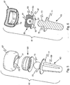
- FIGS. 1 through 4 Illustrated in FIGS. 1 through 4 is a prosthetic implant 11 designed to replace the proximal end portion of the radius.
- the implant 11 consists of three components: a metal alloy stem element 13, a plastic insert 15 and a head 17 of a brittle, crystalline, nonmetallic material, preferably a pyrocarbon-coated graphite substrate.
- the implant provides an axisymmetric prosthesis similar to that shown in U.S. Patent No. 6,217,616 , entitled Elbow Prosthesis.
- brittle is meant a crystalline material that fractures or fails instead of undergoing permanent deformation; such materials, although strong in compression, are inherently weak in tension.
- the stem element 13 includes a stem portion 19 that is proportioned to be received in the medullary cavity of the resected radius.
- the stem portion may have any suitable cross-section, e.g. conical, cylindrical, polygonal or splined; it is designed to resist rotation relative to the radius once implantation has taken place.
- the radial axis is defined as the axis which passes through the proximal and distal heads of the radius.
- the stem element 13 is formed with a thin, circular flange 21 extending radially outward therefrom at a location intermediate its ends; the flange 21 defines the end of the implanted stem portion 19. When implanted, the undersurface of the flange 21 seats against the end surface of the resected radius.
- a connector 23 is constructed at the end of the stem, which is separated from the flange 21 by a neck 25 of reduced diameter.
- the flange 21, the connector 23 and the neck 25 are all circular in cross-section (when viewed in planes perpendicular to the axis of the stem), they could, if desired, be of polygonal or other suitable cross-section.
- the neck 25 thus provides a reentrant region between the flange 21 and the undersurface of the connector 23.
- the stem element 13 is preferably machined from a strong, biocompatible, metal alloy.
- Materials such as titanium, stainless steel, and cobalt-chrome-molybdenum alloys that are biocompatible may be used. Such materials have the strength desirable to provide a strong replacement implant at a joint or the like where it will be subject to stresses.
- the head 17 at the end of the implant will interface with the patient's native bones, and is made of a crystalline, nonmetallic material, e.g. a ceramic, which is inherently brittle.
- alumina and zirconia ceramics are very useful for many applications, it has been found that a dense pyrocarbon surface has superior properties for such an implant with an articular interface, and such is desirable and preferred.
- a dense, isotropic graphite substrate 31 that is coated with a uniform layer 33 of pyrocarbon continuously about its entire exterior surface is found to provide excellent performance.
- the pyrocarbon coating 33 should be at least about 200 microns thick for surfaces that will be subject to wear, preferably at least about 400 microns thick, and more preferably between about 500 and about 1000 microns thick.
- a coating thickness of about 50 microns or more should be adequate.
- the axial end of the head 17 of the illustrated insert 11 slides on the capitulum during flexion and extension of the elbow, and it generally rotates on the capitulum during pronation and supination of the forearm and hand.
- the contact with the capitulum resists valgus forces applied to the arm, and also resists axial loads transmitted from the wrist to the elbow resulting from the gripping function of the hand. It is for this purpose that the axial end of the head 17 is provided with a shallow concave surface 27.
- the lateral surface of the radius head is received in the radial notch that is formed in the medial portion of the ulna.
- the head 17 is formed with a generally barrel-shapes exterior surface 29 to interface well at the radial notch of the ulna.
- the head 17 of the radius is retained in this location at the elbow by the radial collateral ligament and the annular ligament of the radius.
- the annular ligament is attached to the ulna and is supported by the collateral ligament, which is in turn attached to the humerus, extending from a lateral region of the capitulum and being disposed about the head and over the annular ligament.
- pyrolytic carbon-coated, graphite substrates can be used to create prostheses having a modulus of elasticity within about 150% of the modulus of elasticity of natural bone; thus, this is considered to be a preferred material for manufacturing such prostheses.
- a particular pyrocarbon which is being marketed as On-X carbon (see U.S. Pat. No. 5,641,324 ) has advantageous properties for use in orthopedic prostheses such as these, particularly when such is coated upon a substrate of isotropic, fine grain graphite. The result is the creation of a strong radial component prosthesis which has excellent biomechanical properties.
- pyrocarbon is both physiologically inert and biochemically compatible with bone, and because the elastic modulus of such a pyrocarbon-coated graphite substrate is very close to that of cortical bone, such a prosthesis is highly biomechanically compatible and may be effectively used in such orthopedic implants, particularly those at joints within the human body where its articular surface is important.
- pyrocarbon, and particularly On-X carbon illustrates excellent wear characteristics at its interface with bone and also with cartilage, resulting in an implant which is highly bone compatible.
- the head 17 is made from a machined substrate of isotropic graphite 31 that is then coated with pyrocarbon in a fluidized bed coating apparatus, as known in this art, so as to provide a continuous pyrocarbon surface 33 about its entire exterior, as best seen in FIG. 2 .
- a carefully designed polymeric insert 15 is used, which is received in an interior central cavity 35 located in the held 17.
- the cavity 35 is axially aligned and includes an interior cylindrical wall 37 which is a surface of a right circular cylinder.
- the cavity 35 has an entrance 39 in the form of a reentrant arcuate lip of at least about 10% smaller diameter; it is designed to capture the peripheral portion of the polymeric insert 15 therewithin in a pocket created by the lip.
- the head 17 is very effectively joined to the insert 15, which is thereafter mated to the connector 23 at the end of the stem element 13.
- a metal alloy stem for seating in the medullary cavity of the resected radius (or other such bone) and a pyrocarbon-coated graphite head for interfacing with and articulating with adjacent bones, e.g. the ulna and the humerus, allows one to take advantage of the preferred mechanical properties of both structural materials so long as a satisfactory arrangement mating the metallic stem and the crystalline head can be effectively and efficiently provided.
- the polymeric insert 15 is designed and used; it is designed to take into consideration the relative stiffness and Young's Modulus of each of these two diverse materials, and particularly the brittleness of isotropic crystalline graphite, and effectively mate the two materials.
- UHMWPE ultrahigh molecular weight polyethylene
- ASTM Standard F648 ASTM Standard F648
- UHMWPE ultrahigh molecular weight polyethylene
- Such UHMWPE will have a tensile modulus of about 100,000 psi; it will prevent subsequent disassembly, particularly when the desired interference fit is achieved by appropriately proportioning the components.
- the polymeric insert is formed with an exterior lateral surface or wall 41 that is shaped to juxtapose with and, if desired, create a low stress interference fit against the interior wall surface 37 in the pocket within the pyrocarbon head 17.
- the upper end of the lateral wall of the insert is chamfered to provide a tapered surface 43, and the lower exterior region of the insert is constructed with a neck defined by a groove 45 located just above a circular bottom flange 47, which has a flat undersurface that is designed to juxtapose with the upper surface of the flange 21 of the stem element, seating fairly tightly against it if desired.
- the entrance lip 39 to the cavity 35 in the pyrocarbon head 17 is a convex surface section of a torus
- the exterior circumferential groove 45 in the insert is a similarly shaped concave toroidal surface section.
- the dimensioning is such that an annular gap 48 of crescent shape in cross-section is provided between the facing toroidal surfaces in the subassembly, which serves as a relief region as described hereinafter.
- the upper end of the insert has an optional opening 49 at the top; however, alternatively, its upper end it could be closed if desired.
- the polymeric insert 15 has an interior cavity 51 that is designed to receive and mate with the exterior surface of the connector 23 at the end of the stem element.
- the cavity 51 has an interior, right circular, cylindrical surface 53 to mate with the surface of the same shape that forms the lateral exterior of the connector 23.
- the polymeric insert 15 is formed with an entrance region 55 at its lower end having an upwardly and inwardly tapered surface.
- the entrance region 55 terminates with an annular locking ring 57 that will, when mated with the connector 23, interengage or seat against an annular undersurface 59 that is formed on the connector 23 of the stem element at the location where it meets the neck 25.
- the diameter of the cavity 51 is preferably at least about 5% greater than the inner diameter of the locking ring 57 at the upper end of entrance 55.
- the implant 11 is illustrated in FIG. 3 with the stem element 13 spaced from a subassembly wherein the insert 15 has been mated with the pyrocarbon-coated head 17.
- the subassembly depicted in FIG. 3 is simply achieved by relative movement of the head 17 and the insert 15 along the central axis. There is initial engagement between the tapered chamfer surface 43 and the reentrant arcuate entrance lip 39 leading to the cavity of the head 17.
- the UHMWPE material chosen for the insert 15 has sufficient elasticity that allows it to be gradually radially inwardly compressed as the hollow insert passes through the reduced circular region of the entrance lip 39; the components are appropriately sized so that the elastic limit of the polymer is not exceeded.
- the polymeric insert Once in place within the pocket provided in the head cavity 35, the polymeric insert returns to its original dimensions, and if desired, it may effect an interference fit between the juxtaposed surfaces 41 and 37.
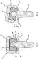
- the arcuate entrance lip 39 leading to the head cavity 35 is seated snugly in the exterior groove 45 in the polymeric insert which pinches against it along two axially spaced circular regions, as seen in FIG. 3A .
- the proportioning is such to leave an annular gap 48 of crescent-shaped cross-section which serves a relief purpose described hereinafter. This seating, along with any interference fit between the two cylindrical surfaces, locks the subassembly components in tight interengagement.
- Interfitting and tight interengagement provides a strong composite head; the physical character of the polymeric material of the insert combines with the physical character of pyrocarbon-coated graphite to provide a composite head which exhibits improved overall strength and physical properties, compared to an inherently brittle, pyrocarbon-coated graphite head.
- the polymeric insert 15 can preferentially absorb shock and insulate the head from possible fracture, and it can also cushion loading at the joint that would otherwise directly stress the pyrocarbon-coated graphite.
- the gap 48 is sized to accommodate an adequate amount of elastic movement in the wall of the insert in this region. This circumferential relief avoids any significant plastic flow of the polymer as the larger diameter connector 23 passes therethrough which preserves the contour of the locking ring 57 to assure an ultimate locking fit of it and the undersurface flange 59 of the connector 23.
- the flat undersurface of the flange 47 at the bottom of the insert has become juxtaposed with the upper surface of the circular flange 21 of the stem, and the connector 23 is seated in the mating cavity 51 of the insert.
- the locking ring 57 which has been preserved as a result of the presence of the relief gap 48, is juxtaposed with the facing annular undersurface 59 of the connector, where it meets the neck, so that the connector 23 of the stem cannot be withdrawn from the overall assembly without deforming the locking ring portion of the entrance region of the polymeric insert.
- the proportioning of the interior cavity 51 of the polymeric insert and the exterior surface of the connector 23 can be held to close tolerances, any desired relationship can be reasonably attained.
- the dimensioning can be such, as described above, that an interference fit is achieved between the lateral surface of the connector 23 and the interior surface of the insert cavity 51.
- the proportioning could be such that there would be sufficient clearance between the exterior surface of the connector 23 and the interior facing surfaces of the polymeric insert cavity that rotational movement about the axis would be permitted.
- the entrance region 55 would be sized so that it would permit rotation about the interface between the entrance region flange 47 and the flange surface 21 of the stem element 13.
- FIGS. 5 through 8 Illustrated in FIGS. 5 through 8 is an alternative embodiment showing an implant 61 where the attitude of the head may be allowed to vary slightly with respect to the axis of the stem.
- the implant 61 again consists of an assembly of three components, a metal stem element 63, a polymeric insert 65 and a pyrocarbon-coated graphite head 67.
- the metal alloy stem element 63 includes an implantable stem portion 69, a circular flange 71 and a connector 73, which in this embodiment is a section of a sphere, that surmounts a neck 75.
- the spherical surface of the connector 73 is at least about 10% greater than that of a hemisphere, and preferably at least about 40% greater and more preferably at least about 80% of the surface of a sphere.
- the head 67 is essentially the same as the head 17 described hereinbefore; it is an isotropic graphite substrate that is coated with a continuous coating of pyrocarbon having a thickness of at least about 200 microns across its entire exterior surface.
- the pyrocarbon coating is continuous so as to cover the walls of its interior cavity 77, entry to which cavity is through a similar entrance having a reentrant lip 79.
- the exterior lateral surface of the polymeric insert 65 is again essentially the same as heretofore described.
- this polymeric insert has a flat upper surface 81, which is juxtaposed with the flat interior surface that forms the upper end of the cavity 77 in the head, and it has a cylindrical, lateral wall 83, which is received in the pocket in the head and proportioned to juxtapose with and, if desired, form an interference fit within the mating, pyrocarbon-coated, interior lateral surface of the cavity 77.
- the polymeric insert 65 likewise has a groove 85 which receives the reduced diameter reentrant lip 79 of the head, which groove 85 is located just above a circular flange 87 at the bottom of the insert. It is proportioned to leave a relief gap 88 similar to the gap 48 of crescent shape cross-section.
- the interior cavity 89 of the insert is spherical so as to mate with the spherical connector 73 at the end of the stem element 63.
- the cavity 89 again has an annular arcuate entrance 91 of reduced diameter leading into the spherical cavity; the cavity 89, if cut by an axial plane, would subtend an arc of at least about 220° and preferably at least about 240°, e.g. between about 240° and 250°, which assures locking the connector 73 within the head subassembly.
- the annular entrance 91 of the insert is shaped to provide a tapered lead-in surface 92. It may be arcuate as illustrated, e.g.
- the circular edge where the entrance meets the cavity 89 is preferably slightly rounded, e.g. a radius of about 0.020 in. (0.5 mm) might be used.
- the implant 61 is constructed so as to be bi-polar, a term used in orthopedics to indicate that the attitude of the head 67 can be varied relative to the axis of the implant.
- the stem element has a neck 75 that is elongated, relative to the neck 25, so that, as seen in FIG. 7 , the undersurface of the flange 87 at the bottom of the insert is spaced apart from the flange 71 of the stem 63 when the head is aligned coaxially with the stem.
- the upper surface of the flange 71 on the stem element is preferably shaped to have a peripheral frustoconical surface region 93.
- the head 67 of the insert 61 can change in attitude by pivoting along an arc in any direction; moreover, it can rotate on the connector.
- the amount of pivoting allowed from the coaxial alignment shown in FIG. 7 , in one direction in the axial plane of the implant will be limited to the extent of about 5-15°.
- Comparison of FIGS. 7 and 8 shows such maximum pivoting in one direction by an arc of the angle ⁇ ; preferably, the pivoting allowed is not greater than about 10°.
- the illustrated arrangement not only provides effective joinder between a somewhat brittle pyrocarbon-coated graphite insert and a metal stem, but it also results in a strengthened composite unit which is bi-polar, i.e. allowing a change in attitude of as much as angle ⁇ of arc in any direction from a coaxial attitude where flange 87 of the insert 65 is perpendicular to the axis of the stem element 63.
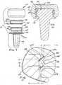
- FIGS. 9, 10 and 11 Illustrated in FIGS. 9, 10 and 11 is another alternative embodiment showing an implant 111 which, from its exterior appearance ( FIG. 10 ), closely resembles the implant 11; however, the design of the polymeric insert and its interengagement with the connector of the stem element is different, while the pyrocarbon-coated head is only slightly different.
- the implant 111 consists of an assembly of three components: a metal stem element 113, a polymeric insert 115, and a pyrocarbon-coated graphite head 117.
- the metal alloy stem element 113 includes an implantable stem portion 119, a circular flange 121, and a connector 123 which resembles the connector 23, being separated from the flange by a short neck 125. However, it includes a circumferential groove 126 which cooperates in the interengagement with the polymeric insert 115.
- the head 117 is essentially the same as the head 17 as described hereinbefore; it is an isotropic graphite substrate that is coated with a continuous coating of pyrocarbon having a thickness of at least about 200 microns across the shallow, concave surface 127 at its axial end and the lateral exterior surface 129.
- the carbon coating is continuous so as to cover the wall surface of an interior cavity 131 has a lateral interior wall 133 of right circular cylindrical shape 133 that terminates in a pair of transitional surfaces 135a and 135b which lead to the flat upper wall of the cavity and to the reentrant lip 137 which forms the entrance to the cavity 131 of lesser diameter than the lateral wall surface 133.
- the polymeric insert 115 is in the shape of a sleeve which fits entirely within the confines of the pyrocarbon-coated head 117. It is again formed from a suitable polymeric material, preferably UHMWPE, having suitable elastic properties as described hereinbefore.
- the sleeve is formed with a lateral surface 141 that is a surface of a right circular cylinder that terminates in a pair of transitional surfaces 143a and 143b that match the shape of the surfaces 135a and b on the interior cavity of the pyrocarbon head and are juxtaposed therewith when assembled.
- the lateral surface 141 is interrupted by a central annular groove 145 which serves as a relief region as described hereinafter.
- the sleeve has an interior surface 147, which is also that of a right circular cylinder, from which there is a central protruding circumferential flange 149 of arcuate shape that serves to interengage the polymeric insert 115 and the connector 123 at the head of the stem element.
- the circumferential groove 126 in the connector 123 is formed with a depth (H2 in FIG. 11 ) so as to receive the circumferential flange 149 of the insert and with a pair of parallel radial walls 151 that transition between its outer cylindrical surface 123 and the base of the groove.
- the walls 151 are spaced apart by the distance W1 in FIG. 11 .
- a subassembly of the pyrocarbon-coated graphite head 117 and the polymeric insert 115 is first made, as previously described, by relative movement of the two so that the insert enters through the narrowed entrance provided by the protruding lip 137.
- the arcuate transitional surface 143a at the end of the insert, serves as a tapered lead-in surface that begins the radially inward elastic deformation of the generally tubular insert 115 as it moves past the narrower diameter of the lip 137. Once fully in place within the cavity 131 of the head, it returns to its original shape.
- the insert is preferably proportioned so as to create an interference fit with the lateral surface 133 of the cavity of the head, with the two transitional surfaces 143a and b juxtaposing with the facing surfaces 135a and b of the head cavity.
- Proportioning is preferably such that the width of the protruding flange 149 is about the same as the dimension W1 of the groove 126, and that the depth H1 of the relief groove 145 is about the same as the thickness H2 of the protruding flange (which is about equal to the depth of the connector groove 126).
- the pyrocarbon head be closed at its top; a head could be more in the form of a sleeve from which the end of the stem element would protrude; head surface character is simply dictated by the desired articular surface of the resultant implant.
- the stem element need not include a circumferential flange, although such is preferred as it provides a positive location for placement of the implant in the bone being repaired.
- the head for the implant is described as preferably being made from pyrocarbon-coated, isotropic graphite, particularly when the implant is to be used at a location where there is articulation
- the invention is also advantageous for the assembly of other crystalline, nonmetallic brittle material heads to a metal stem, for example, ceramic heads that likewise are brittler and have significant differences in physical properties from metal alloy stems.
- the method of forming a composite implant including a high tensile strength metal alloy stem element and a crystalline, brittle head, particularly one having an articular surface, opens up the opportunity for prosthesis design to take advantage of desired features of materials for both head and stem construction.
- the method of joinder of two such components of differing physical properties that, in addition, enhances the operational character of the head and renders the method particularly valuable.
- the cross-sectional geometry of the polymeric insert circumferential flange instead of the flange having a cross-section of a circle, other suitable cross-sections may be used, e.g. trapezoidal or triangular. It is also possible to reverse the interference snap lock mechanism so that the polymeric insert is first assembled on the metal stem component to form the initial subassembly.
- This subassembly would then be inserted into the head cavity, with the arrangement being such that a radially outwardly protruding circumferential flange is radially inwardly deformed until it reaches an appropriately shaped groove or pocket located in the interior wall of the head component, where the flange snaps outward into a locking interengagement.
Landscapes
- Health & Medical Sciences (AREA)
- Orthopedic Medicine & Surgery (AREA)
- Physical Education & Sports Medicine (AREA)
- Cardiology (AREA)
- Oral & Maxillofacial Surgery (AREA)
- Transplantation (AREA)
- Engineering & Computer Science (AREA)
- Biomedical Technology (AREA)
- Heart & Thoracic Surgery (AREA)
- Vascular Medicine (AREA)
- Life Sciences & Earth Sciences (AREA)
- Animal Behavior & Ethology (AREA)
- General Health & Medical Sciences (AREA)
- Public Health (AREA)
- Veterinary Medicine (AREA)
- Prostheses (AREA)
Claims (17)
- Implant prothétique (11, 61) destiné à être implanté dans un os réséqué au niveau d'une articulation, lequel implant comprend :un élément de tige métallique (13, 63) qui a un connecteur (23, 73) au niveau d'une extrémité qui est formé avec une région rentrante de dimension réduite,un insert polymère solidaire d'un seul tenant (15, 65) qui a une cavité intérieure (51, 89) qui reçoit ledit connecteur et une bride (47, 87) qui entoure une entrée de ladite cavité, etune tête (17, 67) ayant une surface articulaire extérieure (29) et une cavité intérieure (35, 77) proportionnée pour recevoir ledit insert, ladite tête étant formée à partir d'un substrat en graphite ayant des surfaces intérieure et extérieure de pyrocarbone,ladite cavité de tête ayant une entrée formée par une lèvre d'entrée rentrante (39, 79) d'un moindre diamètre interne et une taille telle que ledit insert polymère doit se déformer élastiquement radialement vers l'intérieur pour entrer dans ladite cavité,ladite cavité d'insert polymère ayant une région d'entrée d'une taille inférieure audit connecteur et ayant une rainure externe (45, 85) qui reçoit ladite lèvre d'entrée de tête et quitte un espace annulaire (48, 88) formant une région de relief circonférentielle qui accepte la déformation élastique dudit insert polymère lorsque ledit élément de tige est assemblé avec un sous-ensemble de ladite tête et dudit insert polymère, etledit insert polymère solidaire étant réalisé avec un matériau polymère présentant une élasticité, de sorte que (a) il peut se déformer radialement vers l'intérieur suffisamment pour faciliter son entrée dans ladite cavité de tête et revenir à sa forme, (b) sa région d'entrée peut se déformer radialement vers l'extérieur pour faciliter l'assemblage avec ledit connecteur, et (c) une fois assemblé à la fois avec ladite tête et ledit connecteur de tige, le démontage ne peut pas se produire par inadvertance.
- Implant prothétique (111) destiné à être implanté dans un os réséqué, lequel implant comprend :un élément de tige métallique (113) qui a un connecteur (123) au niveau d'une extrémité qui est formée avec une région rentrante de dimension réduite,un insert polymère solidaire d'un seul tenant (115) qui a une cavité centrale (147) qui reçoit ledit connecteur,une tête (117) formée avec un matériau cristallin fragile ayant une cavité centrale (131) qui est proportionnée pour recevoir complètement ledit insert, dans lequel ledit insert se présente sous la forme d'un manchon qui est monté entièrement dans les limites de la tête,ladite cavité de tête ayant une entrée d'une taille telle qu'au moins une partie dudit insert polymère doit se déformer élastiquement vers l'intérieur pour pénétrer dans ladite cavité,ladite cavité centrale d'insert étant formée avec des moyens (137) pour se mettre en prise avec ledit connecteur qui nécessite la déformation radialement vers l'extérieur d'au moins une partie dudit insert afin de verrouiller ledit insert et ledit connecteur en mise en prise, etdes moyens fournissant une région de relief circonférentielle (145) dans laquelle une partie dudit insert polymère peut élastiquement se déformer,ledit insert polymère solidaire étant réalisé à partir d'un matériau polymère présentant une élasticité, de sorte que (a) il peut se déformer radialement vers l'intérieur suffisamment pour faciliter son entrée dans ladite cavité de tête et revenir ensuite à sa forme, (b) il peut se déformer radialement vers l'extérieur pour faciliter l'assemblage avec ledit connecteur et ensuite revenir à sa forme, et (c) une fois assemblé à la fois avec ladite tête et ledit connecteur de tige, le démontage ne peut pas de produire par inadvertance, avec ledit assemblage final qui est facilité par ledit emplacement de la région de relief.
- Implant selon la revendication 1 ou 2, dans lequel ledit insert polymère a une paroi cylindrique latérale extérieure (41, 83, 141) de section transversale circulaire et une région d'extrémité progressivement rétrécie (43, 143a) afin de faciliter son entrée dans ladite entrée de ladite cavité de tête.
- Implant selon la revendication 3, dans lequel ladite cavité de tête et ledit insert ont des surfaces cylindriques correspondantes et le diamètre de ladite surface externe cylindrique dudit insert polymère est tel que l'assemblage dudit insert à l'intérieur de ladite tête crée un ajustement avec serrage au niveau desdites surfaces cylindriques.
- Implant selon la revendication 4, dans lequel ledit élément de tige a une bride radiale (21, 71, 121) de forme généralement circulaire positionnée entre ladite une extrémité et ledit connecteur.
- Implant selon la revendication 5, dans lequel ledit connecteur est assemblé au reste dudit élément de tige métallique par une partie de col (25, 75, 125) de dimension réduite qui s'étend à partir de ladite bride radiale.
- Implant selon la revendication 6, dans lequel ledit diamètre de ladite cavité d'insert polymère est tel que l'assemblage dudit connecteur de tige et dudit insert crée un ajustement avec serrage entre ledit connecteur et ladite surface de ladite cavité d'insert polymère.
- Implant selon la revendication 7, dans lequel ladite cavité d'insert polymère et ladite région d'entrée ont toutes deux une section transversale circulaire, avec ladite cavité qui a un diamètre qui est au moins environ 5 % supérieur au diamètre de ladite entrée circulaire.
- Implant selon la revendication 8 lorsqu'elle dépend de la revendication 2, dans lequel ledit insert polymère a un col extérieur (45, 85) de diamètre réduit par rapport à celui de sa surface de paroi externe cylindrique, lequel col est positionné de manière adjacente à une bride (41, 87) s'étendant vers l'extérieur entourant ladite région d'entrée.
- Implant selon la revendication 9, dans lequel ladite tête est réalisée à partir de graphite, dont toutes les surfaces sont recouvertes avec un revêtement continu de pyrocarbone, et a une lèvre rentrante qui forme ladite entrée dans ladite cavité de tête, laquelle lèvre a une surface annulaire convexe et dans lequel ledit col extérieur d'insert est la rainure avec une surface annulaire concave qui reçoit ladite tête et quitte l'espace annulaire (48, 88) qui forme ladite région de relief et accepte la déformation élastique dudit insert polymère, ledit élément de tige est assemblé avec un sous-ensemble de ladite tête et dudit insert polymère.
- Implant selon la revendication 10, dans lequel ladite lèvre et ladite rainure ont des surfaces toroïdales avec un espace en forme de croissant (48, 88) entre elles.
- Implant selon la revendication 9, dans lequel ladite partie de col (75) dudit élément de tige a une longueur de sorte qu'avec ladite tête, ledit insert et ledit élément de tige assemblés entre eux, ladite bride dudit insert est juxtaposée à ladite bride de ladite tige.
- Implant selon la revendication 4 lorsqu'elle dépend de la revendication 2, dans lequel ladite cavité d'insert polymère (89) a une surface sphérique et dans lequel le diamètre de ladite région d'entrée d'insert polymère (91) est compris entre environ 70 % et environ 85 % du diamètre de la cavité d'insert sphérique, dans lequel ledit connecteur (73) est une section d'une sphère d'au moins environ 10 % supérieure à une hémisphère, dans lequel ladite cavité d'insert a une surface intérieure sphérique, et dans lequel ledit col de ladite tige a une longueur de sorte que lesdits tête et insert assemblés peuvent pivoter sur ledit connecteur dans n'importe quelle direction sur un arc compris entre environ 5° et environ 15°.
- Implant selon la revendication 4 lorsqu'elle dépend de la revendication 1, dans lequel lesdits moyens de mise en prise comprennent une rainure circonférentielle (126) formée dans ledit connecteur et une bride annulaire (149) faisant saillie radialement vers l'intérieur à partir d'une paroi de ladite cavité centrale d'insert polymère, laquelle bride en saillie est reçue dans ladite rainure circonférentielle, dans lequel lesdits moyens de relief sont fournis par un creux circonférentiel (145) dans la surface extérieure dudit insert polymère qui est positionné environ au même emplacement axial sur ledit insert que ladite bride en saillie, et dans lequel le volume transversal dudit creux annulaire représente au moins environ 90 % du volume de ladite bride en saillie.
- Implant selon la revendication 14, dans lequel ladite bride en saillie (149) et ledit creux circonférentiel (145) ont des surfaces arquées lorsqu'ils sont coupés par un plan axialement aligné, et dans lequel ladite rainure circonférentielle (126) a une paire de surfaces radiales (151) espacées qui sont sensiblement parallèles entre elles et essentiellement perpendiculaires audit axe dudit élément de tige, dans lequel ledit insert polymère a des surfaces extérieure et intérieure cylindrique et une paire de surfaces distale et proximale de transition espacées (135a, 135b) qui s'étendent entre lesdites surfaces intérieure et extérieure, dont l'une sert de surface d'entrée progressivement rétrécie lorsque ledit insert est assemblé à ladite tête, lesdites surfaces de transition étant juxtaposées avec des surfaces similaires qui sont prévues à l'intérieur de ladite cavité centrale de ladite tête.
- Procédé pour former un implant prothétique, ledit procédé comprend les étapes consistant à :prévoir un implant prothétique selon la revendication 2 ou l'une quelconque des revendications 3 à 13 lorsqu'elle dépend de la revendication 2 ;former un sous-ensemble en couplant ledit insert polymère avec ladite tête par l'insertion dudit insert à travers ladite entrée dans ladite cavité de tête d'une manière selon laquelle le matériau polymère se déforme élastiquement radialement vers l'intérieur afin de faciliter son entrée et le retour à sa forme dans ladite cavité de tête, etterminer ensuite ledit implant prothétique en couplant ledit sous-ensemble avec ledit élément de tige en insérant ledit connecteur dans ladite cavité intérieure à l'intérieur dudit insert polymère en amenant ledit matériau polymère à se déformer élastiquement radialement vers l'extérieur au niveau d'une mise en prise mutuelle de la rainure de l'insert et de la lèvre d'entrée de tête où il est logé par la région de relief circonférentielle (48, 88, 145) et ensuite à revenir à une configuration ayant un diamètre intérieur qui empêche ensuite le démontage par inadvertance dudit sous-ensemble de tête dudit élément de tige.
- Procédé pour former un implant prothétique, lequel procédé comprend les étapes consistant à :prévoir un élément de tige en alliage de métal (13, 63, 113) qui a un connecteur (23, 73, 123) au niveau d'une extrémité qui est formée avec une région diamétrale réduite,prévoir une tête (17, 67, 117) réalisée avec un matériau cristallin fragile ayant une cavité (35, 71, 131) formée avec une entrée (39, 79, 137) de diamètre réduit,prévoir un insert polymère solidaire (15, 65, 115) qui est proportionné pour s'installer complètement à l'intérieur de ladite cavité dans ladite tête, lequel insert a une cavité centrale intérieure (51, 98, 147) qui est proportionnée pour recevoir ledit connecteur à l'extrémité dudit élément de tige et pour se mettre en prise avec ce dernier au niveau de ladite région de connecteur de diamètre diamétrale réduite, dans lequel ledit insert se présente sous la forme d'un manchon,former un sous-ensemble en couplant ledit insert polymère avec ladite tête par l'insertion dudit insert à travers ladite entrée dans ladite cavité de tête d'une manière selon laquelle le matériau polymère se déforme élastiquement radialement vers l'intérieur afin de faciliter son entrée et le retour à sa forme dans ladite cavité de tête de sorte que ledit insert est monté entièrement dans les limites de la tête, etterminer ensuite ledit implant prothétique en couplant ledit sous-ensemble avec ledit élément de tige en insérant ledit connecteur dans ladite cavité intérieure à l'intérieur dudit insert polymère en amenant ledit matériau polymère à se déformer élastiquement radialement vers l'extérieur au niveau desdits moyens de mise en prise où il est logé par une région de relief circonférentielle (48, 88, 145) et ensuite à revenir à une configuration ayant un diamètre intérieur qui empêche ensuite le démontage par inadvertance dudit sous-ensemble de tête dudit élément de tige.
Applications Claiming Priority (2)
| Application Number | Priority Date | Filing Date | Title |
|---|---|---|---|
| US74366106P | 2006-03-22 | 2006-03-22 | |
| PCT/US2007/064594 WO2007109752A2 (fr) | 2006-03-22 | 2007-03-22 | Implant prothétique et son procédé d'assemblage |
Publications (3)
| Publication Number | Publication Date |
|---|---|
| EP2001410A2 EP2001410A2 (fr) | 2008-12-17 |
| EP2001410A4 EP2001410A4 (fr) | 2009-12-30 |
| EP2001410B1 true EP2001410B1 (fr) | 2016-12-28 |
Family
ID=38523306
Family Applications (1)
| Application Number | Title | Priority Date | Filing Date |
|---|---|---|---|
| EP07759077.6A Not-in-force EP2001410B1 (fr) | 2006-03-22 | 2007-03-22 | Implant prothétique et son procédé d'assemblage |
Country Status (3)
| Country | Link |
|---|---|
| US (3) | US8034116B2 (fr) |
| EP (1) | EP2001410B1 (fr) |
| WO (1) | WO2007109752A2 (fr) |
Families Citing this family (57)
| Publication number | Priority date | Publication date | Assignee | Title |
|---|---|---|---|---|
| US7160329B2 (en) | 2004-12-01 | 2007-01-09 | Mayo Foundation For Medical Research And Education | Radial-capitellar implant |
| WO2008022471A1 (fr) * | 2006-08-22 | 2008-02-28 | Synthes Gmbh | dispositif de remplacement total d'un disque |
| US8715350B2 (en) | 2006-09-15 | 2014-05-06 | Pioneer Surgical Technology, Inc. | Systems and methods for securing an implant in intervertebral space |
| US8377133B2 (en) | 2006-09-15 | 2013-02-19 | Pioneer Surgical Technology, Inc. | Systems and methods for sizing, inserting and securing an implant in intervertebral space |
| AU2007325130B2 (en) | 2006-11-29 | 2012-07-26 | Ascension Orthopedics, Inc. | Shoulder joint implant |
| US9636228B2 (en) | 2007-02-10 | 2017-05-02 | Howmedica Osteonics Corp. | Radial head implant |
| FR2923154B1 (fr) * | 2007-11-05 | 2009-12-25 | Ass Guepar | Ensemble prothetique d'une articulation comprenant une serie de tiges de taille differentes et presentant une tete d'articulation destinee a recevoir une cupule |
| US8043375B2 (en) | 2008-03-06 | 2011-10-25 | MoiRai Orthopaedic, LLC | Cartilage implants |
| US8012217B2 (en) | 2008-07-03 | 2011-09-06 | Fellowship of Orthopaedic Researchers, LLC | Talar implants and methods of use |
| FR2940760B1 (fr) | 2009-01-08 | 2010-12-31 | Memometal Technologies | Implant orthopedique pour arthroplastie digitale |
| BRPI1008295A2 (pt) | 2009-02-19 | 2016-03-15 | Nextremity Solutions Llc | aparelho e método de junção de ossos |
| US9072562B2 (en) | 2009-02-19 | 2015-07-07 | Nextremity Solutions, Inc. | Bone joining device, kit and method |
| US9468465B2 (en) | 2009-02-19 | 2016-10-18 | Nextremity Solutions, Inc. | Reversible bone coupling device and method |
| JP2012525942A (ja) * | 2009-05-07 | 2012-10-25 | スミス アンド ネフュー インコーポレーテッド | モジュール式試行プロテーゼヘッド |
| ES2671056T3 (es) | 2009-08-06 | 2018-06-04 | Skeletal Dynamics, Llc | Sistema de prótesis articular alineable |
| CA2771555C (fr) | 2009-08-25 | 2016-09-13 | Fellowship Of Orthopaedic Researchers, Inc. | Implants trochleaires et procedes d?utilisation |
| USD685474S1 (en) | 2010-07-06 | 2013-07-02 | Tornier, Inc. | Prosthesis anchor |
| US8690956B2 (en) | 2010-08-23 | 2014-04-08 | Fellowship Of Orthopaedic Researchers, Inc. | Talar implants and methods of use |
| AU2011314157A1 (en) * | 2010-09-29 | 2013-05-09 | Zimmer, Inc. | Pyrolytic carbon implants with porous fixation component and methods of making the same |
| EP2706960B1 (fr) * | 2011-05-12 | 2016-01-06 | Howmedica Osteonics Corp. | Implant de poignet pour hémi-arthroplastie carpienne |
| FR2984781B1 (fr) * | 2011-12-22 | 2014-01-24 | Commissariat Energie Atomique | Procede d'assemblage par brasage d'un substrat comprenant du pyrocarbone avec des pieces comprenant du pyrocarbone. |
| US9486322B2 (en) * | 2012-06-19 | 2016-11-08 | Christopher Sterling Pallia | Carpometacarpal prosthesis system and method of using same |
| GB2524668A (en) | 2012-09-10 | 2015-09-30 | Acumed Llc | Radial head prosthesis with floating articular member |
| US9901452B2 (en) | 2013-03-14 | 2018-02-27 | Imds Corporation | Radial head implant |
| US8974538B2 (en) * | 2013-03-15 | 2015-03-10 | Steven M. Teeny | Orthopedic spacer |
| US10357372B2 (en) * | 2013-03-28 | 2019-07-23 | Mayo Foundation For Medical Education And Research | Radial head trials |
| US12023253B2 (en) | 2014-01-24 | 2024-07-02 | Howmedica Osteonics Corp. | Humeral implant anchor system |
| US10456264B2 (en) | 2014-01-24 | 2019-10-29 | Tornier, Inc. | Humeral implant anchor system |
| EP2904987B1 (fr) * | 2014-02-11 | 2018-12-19 | Kulzer GmbH | Prothèse dentaire avec insert d'amortissement |
| FR3021524A1 (fr) * | 2014-06-02 | 2015-12-04 | Small Bone Innovations Internat | Tige d'ancrage metacarpien, notamment pour une prothese trapezo-metacarpienne |
| US20160270922A1 (en) * | 2015-03-19 | 2016-09-22 | Limacorporate S.P.A. | Glenoid Anchor for a Shoulder Joint Prosthesis |
| US9763792B2 (en) * | 2015-10-01 | 2017-09-19 | Acumed Llc | Radial head prosthesis with rotate-to-lock interface |
| WO2017165727A2 (fr) * | 2016-03-24 | 2017-09-28 | Skeletal Dynamics, Llc | Prothèse totale de poignet et procédés associés |
| US10463499B2 (en) | 2016-03-25 | 2019-11-05 | Tornier, Inc. | Stemless shoulder implant with fixation components |
| WO2017214095A1 (fr) * | 2016-06-07 | 2017-12-14 | Holiday Ron | Doublure souple contrainte destinée à la prothèse de la hanche |
| EP3260087B1 (fr) | 2016-06-24 | 2019-08-07 | Tornier | Ensemble pour un implant glénoïde |
| US11129724B2 (en) | 2016-07-28 | 2021-09-28 | Howmedica Osteonics Corp. | Stemless prosthesis anchor component |
| CN110913804B (zh) * | 2017-04-04 | 2022-03-15 | 托尼尔公司 | 肘关节假体 |
| US11331192B2 (en) | 2017-04-28 | 2022-05-17 | Noel Raels Ortho Devices Incorporated | Frictionless hip joint |
| US10596005B2 (en) | 2017-04-28 | 2020-03-24 | Hector Noel | Frictionless hip joint |
| CN110709034A (zh) * | 2017-06-02 | 2020-01-17 | Ot医疗技术股份有限公司 | 桡骨头植入物 |
| JP7521152B2 (ja) | 2017-09-08 | 2024-07-24 | エクスタント メディカル ホールディングス,インコーポレイテッド. | 椎間インプラント、器具、及び方法 |
| WO2019060780A2 (fr) | 2017-09-25 | 2019-03-28 | Tornier, Inc. | Composants d'ancrage de prothèse sans tige spécifique au patient |
| USD907771S1 (en) | 2017-10-09 | 2021-01-12 | Pioneer Surgical Technology, Inc. | Intervertebral implant |
| US11399948B2 (en) | 2017-12-11 | 2022-08-02 | Howmedica Osteonics Corp. | Stemless prosthesis anchor components and kits |
| US11813166B2 (en) | 2018-03-05 | 2023-11-14 | Synthes Gmbh | Trial radial head implant |
| US11129719B2 (en) * | 2018-03-05 | 2021-09-28 | Synthes Gmbh | Trial radial head implant |
| JP7137943B2 (ja) | 2018-03-20 | 2022-09-15 | 株式会社日立ハイテク | 探索装置、探索方法及びプラズマ処理装置 |
| WO2020072452A1 (fr) | 2018-10-02 | 2020-04-09 | Tornier, Inc. | Composants et ensembles de prothèse d'épaule |
| AU2019354606B2 (en) * | 2018-10-03 | 2021-08-19 | Howmedica Osteonics Corp. | Elbow joint prostheses |
| US11660133B2 (en) | 2018-10-26 | 2023-05-30 | Zimmer, Inc. | Bone coupling device and method |
| AU2020247288B2 (en) * | 2019-03-25 | 2025-08-21 | Loci Orthopaedics Limited | Bone joint implants |
| USD951449S1 (en) | 2019-10-01 | 2022-05-10 | Howmedica Osteonics Corp. | Humeral implant |
| US12370051B2 (en) | 2019-10-01 | 2025-07-29 | Howmedica Osteonics Corp. | Shoulder prosthesis components and assemblies |
| US11992412B2 (en) * | 2020-03-18 | 2024-05-28 | In2Bones Usa, Llc | Radial head fracture treatment system |
| JP7424909B2 (ja) | 2020-05-18 | 2024-01-30 | 株式会社日立製作所 | 処理条件探索装置および処理条件探索方法 |
| WO2024049651A1 (fr) * | 2022-08-31 | 2024-03-07 | Smith & Nephew, Inc. | Ensemble tête humérale de pyrocarbone moulé par compression directe |
Family Cites Families (25)
| Publication number | Priority date | Publication date | Assignee | Title |
|---|---|---|---|---|
| US3707006A (en) * | 1970-08-26 | 1972-12-26 | Gulf Oil Corp | Orthopedic device for repair or replacement of bone |
| CH615585A5 (fr) * | 1977-06-22 | 1980-02-15 | Sulzer Ag | |
| DE2742098C2 (de) * | 1977-09-19 | 1983-01-13 | Rosenthal Technik Ag, 8672 Selb | Endoprothese mit einer Metall-Keramik-Verbindung |
| DE2829676A1 (de) * | 1978-07-06 | 1980-01-24 | Gmt Medizinische Technik Gmbh | Endoprothese |
| US4241463A (en) * | 1978-10-16 | 1980-12-30 | Precision Cast Specialties, Inc. | Prosthetic implant device |
| US4289244A (en) * | 1978-12-08 | 1981-09-15 | The Lightron Corporation | Supporting apparatus for medical bottles and the like |
| FR2511240A1 (fr) * | 1981-08-14 | 1983-02-18 | Bentley Lab | Dispositif d'ureterostomie |
| US4770658A (en) * | 1987-05-01 | 1988-09-13 | Zimmer, Inc. | Joint prosthesis |
| US4795468A (en) * | 1987-12-23 | 1989-01-03 | Zimmer, Inc. | Mechanism and method for locking a bearing insert to the base of a prosthetic implant |
| US4936855A (en) * | 1989-04-24 | 1990-06-26 | Intermedics, Orthopedics, Inc. | Stepped-lock ring system for implantable joint prostheses |
| US4955916A (en) * | 1989-05-01 | 1990-09-11 | Techmedica, Inc. | Thumb joint prosthesis |
| US5062853A (en) * | 1989-08-08 | 1991-11-05 | Forte Mark R | Bipolar femoral implant |
| US4997445A (en) * | 1989-12-08 | 1991-03-05 | Zimmer, Inc. | Metal-backed prosthetic implant with enhanced bonding of polyethylene portion to metal base |
| FR2679440A1 (fr) * | 1991-07-24 | 1993-01-29 | Hades | Prothese articulaire, notamment trapezo-metacarpienne et digitale. |
| FR2686252A1 (fr) * | 1992-01-20 | 1993-07-23 | Fornell Jacques | Raccord d'anastomose. |
| US5551871A (en) * | 1993-03-05 | 1996-09-03 | Besselink; Petrus A. | Temperature-sensitive medical/dental apparatus |
| US5593445A (en) * | 1995-03-24 | 1997-01-14 | Waits; C. Thomas | Bi-axial prosthetic joint |
| DE19620525A1 (de) * | 1996-05-22 | 1997-11-27 | Gmt Medizinische Technik Gmbh | Ellbogengelenk-Endoprothese |
| US6162256A (en) * | 1997-12-29 | 2000-12-19 | Depuy Orthopaedics, Inc. | Acetabular prosthesis |
| US6916342B2 (en) * | 2002-04-01 | 2005-07-12 | Smith & Nephew, Inc. | Liner assembly for prosthetic components |
| FR2840039B1 (fr) * | 2002-05-22 | 2004-11-12 | Bioprofile | Accouplement conique et prothese comprenant un tel accouplement |
| US7641696B2 (en) * | 2003-01-07 | 2010-01-05 | Ascension Orthopedics, Inc. | Carpometacarpal joint prosthesis |
| DE102004020220A1 (de) * | 2004-04-22 | 2005-11-10 | Grünenthal GmbH | Verfahren zur Herstellung einer gegen Missbrauch gesicherten, festen Darreichungsform |
| US20060259148A1 (en) * | 2003-10-28 | 2006-11-16 | Presrv Ltd. | Cartilage-preserving long bone head prosthesis |
| EP1632200A1 (fr) * | 2004-09-02 | 2006-03-08 | ESKA Implants GmbH & Co. | Prothèse pour articulation carpo-métacarpienne |
-
2007
- 2007-03-22 WO PCT/US2007/064594 patent/WO2007109752A2/fr not_active Ceased
- 2007-03-22 EP EP07759077.6A patent/EP2001410B1/fr not_active Not-in-force
-
2008
- 2008-09-19 US US12/233,976 patent/US8034116B2/en active Active
-
2011
- 2011-09-21 US US13/239,067 patent/US20120010724A1/en not_active Abandoned
- 2011-09-22 US US13/240,107 patent/US20120022664A1/en not_active Abandoned
Also Published As
| Publication number | Publication date |
|---|---|
| US8034116B2 (en) | 2011-10-11 |
| US20120022664A1 (en) | 2012-01-26 |
| EP2001410A2 (fr) | 2008-12-17 |
| WO2007109752A3 (fr) | 2008-02-14 |
| US20120010724A1 (en) | 2012-01-12 |
| US20090240336A1 (en) | 2009-09-24 |
| EP2001410A4 (fr) | 2009-12-30 |
| WO2007109752A2 (fr) | 2007-09-27 |
Similar Documents
| Publication | Publication Date | Title |
|---|---|---|
| EP2001410B1 (fr) | Implant prothétique et son procédé d'assemblage | |
| US5645605A (en) | Implant device to replace the carpometacarpal joint of the human thumb | |
| US6699290B1 (en) | Modular elbow | |
| US5263988A (en) | Bipolar endoprosthesis | |
| US7749277B2 (en) | Containment system for constraining a prosthetic component | |
| US5879404A (en) | Acetabular cups and methods of their manufacture | |
| US6096084A (en) | Modular ball and socket joint preferably with a ceramic head ball | |
| US7753960B2 (en) | Modular knee prosthesis | |
| CN101686863A (zh) | 髋臼假体装置 | |
| US20140303743A1 (en) | Inner acetabular liner for a dual mobility femoral head construct | |
| AU2007325130B2 (en) | Shoulder joint implant | |
| EP3914193B1 (fr) | Implants d'articulation osseuse | |
| Derar et al. | Recent patents and designs on hip replacement prostheses | |
| WO2000074604A1 (fr) | Composant acetabulaire d'ensemble de remplacement integral de la hanche | |
| EP3989885B1 (fr) | Implant prothétique | |
| US20200405496A1 (en) | Bone joint implants | |
| US20210007853A1 (en) | Prosthesis for hip replacement with polyethylene head and anti-rotational intra-prosthetic assembly | |
| EP4709323A1 (fr) | Implant d'arthroplastie totale |
Legal Events
| Date | Code | Title | Description |
|---|---|---|---|
| PUAI | Public reference made under article 153(3) epc to a published international application that has entered the european phase |
Free format text: ORIGINAL CODE: 0009012 |
|
| 17P | Request for examination filed |
Effective date: 20081020 |
|
| AK | Designated contracting states |
Kind code of ref document: A2 Designated state(s): AT BE BG CH CY CZ DE DK EE ES FI FR GB GR HU IE IS IT LI LT LU LV MC MT NL PL PT RO SE SI SK TR |
|
| RIN1 | Information on inventor provided before grant (corrected) |
Inventor name: KLAWITTER, JEROME Inventor name: VANDER MEULEN, STEVE |
|
| A4 | Supplementary search report drawn up and despatched |
Effective date: 20091130 |
|
| 17Q | First examination report despatched |
Effective date: 20100319 |
|
| DAX | Request for extension of the european patent (deleted) | ||
| REG | Reference to a national code |
Ref country code: DE Ref legal event code: R079 Ref document number: 602007049328 Country of ref document: DE Free format text: PREVIOUS MAIN CLASS: A61F0002280000 Ipc: A61F0002380000 |
|
| GRAP | Despatch of communication of intention to grant a patent |
Free format text: ORIGINAL CODE: EPIDOSNIGR1 |
|
| RIC1 | Information provided on ipc code assigned before grant |
Ipc: A61F 2/30 20060101ALI20150810BHEP Ipc: A61F 2/38 20060101AFI20150810BHEP |
|
| INTG | Intention to grant announced |
Effective date: 20150901 |
|
| GRAJ | Information related to disapproval of communication of intention to grant by the applicant or resumption of examination proceedings by the epo deleted |
Free format text: ORIGINAL CODE: EPIDOSDIGR1 |
|
| GRAP | Despatch of communication of intention to grant a patent |
Free format text: ORIGINAL CODE: EPIDOSNIGR1 |
|
| GRAP | Despatch of communication of intention to grant a patent |
Free format text: ORIGINAL CODE: EPIDOSNIGR1 |
|
| GRAS | Grant fee paid |
Free format text: ORIGINAL CODE: EPIDOSNIGR3 |
|
| INTG | Intention to grant announced |
Effective date: 20160506 |
|
| GRAA | (expected) grant |
Free format text: ORIGINAL CODE: 0009210 |
|
| AK | Designated contracting states |
Kind code of ref document: B1 Designated state(s): AT BE BG CH CY CZ DE DK EE ES FI FR GB GR HU IE IS IT LI LT LU LV MC MT NL PL PT RO SE SI SK TR |
|
| REG | Reference to a national code |
Ref country code: GB Ref legal event code: FG4D |
|
| REG | Reference to a national code |
Ref country code: CH Ref legal event code: EP |
|
| REG | Reference to a national code |
Ref country code: AT Ref legal event code: REF Ref document number: 856660 Country of ref document: AT Kind code of ref document: T Effective date: 20170115 |
|
| REG | Reference to a national code |
Ref country code: IE Ref legal event code: FG4D |
|
| REG | Reference to a national code |
Ref country code: DE Ref legal event code: R096 Ref document number: 602007049328 Country of ref document: DE |
|
| PG25 | Lapsed in a contracting state [announced via postgrant information from national office to epo] |
Ref country code: LV Free format text: LAPSE BECAUSE OF FAILURE TO SUBMIT A TRANSLATION OF THE DESCRIPTION OR TO PAY THE FEE WITHIN THE PRESCRIBED TIME-LIMIT Effective date: 20161228 |
|
| REG | Reference to a national code |
Ref country code: FR Ref legal event code: PLFP Year of fee payment: 11 |
|
| REG | Reference to a national code |
Ref country code: LT Ref legal event code: MG4D |
|
| PG25 | Lapsed in a contracting state [announced via postgrant information from national office to epo] |
Ref country code: GR Free format text: LAPSE BECAUSE OF FAILURE TO SUBMIT A TRANSLATION OF THE DESCRIPTION OR TO PAY THE FEE WITHIN THE PRESCRIBED TIME-LIMIT Effective date: 20170329 Ref country code: SE Free format text: LAPSE BECAUSE OF FAILURE TO SUBMIT A TRANSLATION OF THE DESCRIPTION OR TO PAY THE FEE WITHIN THE PRESCRIBED TIME-LIMIT Effective date: 20161228 Ref country code: LT Free format text: LAPSE BECAUSE OF FAILURE TO SUBMIT A TRANSLATION OF THE DESCRIPTION OR TO PAY THE FEE WITHIN THE PRESCRIBED TIME-LIMIT Effective date: 20161228 |
|
| REG | Reference to a national code |
Ref country code: NL Ref legal event code: MP Effective date: 20161228 |
|
| REG | Reference to a national code |
Ref country code: AT Ref legal event code: MK05 Ref document number: 856660 Country of ref document: AT Kind code of ref document: T Effective date: 20161228 |
|
| PG25 | Lapsed in a contracting state [announced via postgrant information from national office to epo] |
Ref country code: FI Free format text: LAPSE BECAUSE OF FAILURE TO SUBMIT A TRANSLATION OF THE DESCRIPTION OR TO PAY THE FEE WITHIN THE PRESCRIBED TIME-LIMIT Effective date: 20161228 |
|
| PG25 | Lapsed in a contracting state [announced via postgrant information from national office to epo] |
Ref country code: NL Free format text: LAPSE BECAUSE OF FAILURE TO SUBMIT A TRANSLATION OF THE DESCRIPTION OR TO PAY THE FEE WITHIN THE PRESCRIBED TIME-LIMIT Effective date: 20161228 |
|
| PG25 | Lapsed in a contracting state [announced via postgrant information from national office to epo] |
Ref country code: SK Free format text: LAPSE BECAUSE OF FAILURE TO SUBMIT A TRANSLATION OF THE DESCRIPTION OR TO PAY THE FEE WITHIN THE PRESCRIBED TIME-LIMIT Effective date: 20161228 Ref country code: CZ Free format text: LAPSE BECAUSE OF FAILURE TO SUBMIT A TRANSLATION OF THE DESCRIPTION OR TO PAY THE FEE WITHIN THE PRESCRIBED TIME-LIMIT Effective date: 20161228 Ref country code: IS Free format text: LAPSE BECAUSE OF FAILURE TO SUBMIT A TRANSLATION OF THE DESCRIPTION OR TO PAY THE FEE WITHIN THE PRESCRIBED TIME-LIMIT Effective date: 20170428 Ref country code: EE Free format text: LAPSE BECAUSE OF FAILURE TO SUBMIT A TRANSLATION OF THE DESCRIPTION OR TO PAY THE FEE WITHIN THE PRESCRIBED TIME-LIMIT Effective date: 20161228 Ref country code: RO Free format text: LAPSE BECAUSE OF FAILURE TO SUBMIT A TRANSLATION OF THE DESCRIPTION OR TO PAY THE FEE WITHIN THE PRESCRIBED TIME-LIMIT Effective date: 20161228 |
|
| PG25 | Lapsed in a contracting state [announced via postgrant information from national office to epo] |
Ref country code: BE Free format text: LAPSE BECAUSE OF FAILURE TO SUBMIT A TRANSLATION OF THE DESCRIPTION OR TO PAY THE FEE WITHIN THE PRESCRIBED TIME-LIMIT Effective date: 20161228 Ref country code: AT Free format text: LAPSE BECAUSE OF FAILURE TO SUBMIT A TRANSLATION OF THE DESCRIPTION OR TO PAY THE FEE WITHIN THE PRESCRIBED TIME-LIMIT Effective date: 20161228 Ref country code: BG Free format text: LAPSE BECAUSE OF FAILURE TO SUBMIT A TRANSLATION OF THE DESCRIPTION OR TO PAY THE FEE WITHIN THE PRESCRIBED TIME-LIMIT Effective date: 20170328 Ref country code: ES Free format text: LAPSE BECAUSE OF FAILURE TO SUBMIT A TRANSLATION OF THE DESCRIPTION OR TO PAY THE FEE WITHIN THE PRESCRIBED TIME-LIMIT Effective date: 20161228 Ref country code: PT Free format text: LAPSE BECAUSE OF FAILURE TO SUBMIT A TRANSLATION OF THE DESCRIPTION OR TO PAY THE FEE WITHIN THE PRESCRIBED TIME-LIMIT Effective date: 20170428 Ref country code: PL Free format text: LAPSE BECAUSE OF FAILURE TO SUBMIT A TRANSLATION OF THE DESCRIPTION OR TO PAY THE FEE WITHIN THE PRESCRIBED TIME-LIMIT Effective date: 20161228 |
|
| REG | Reference to a national code |
Ref country code: DE Ref legal event code: R097 Ref document number: 602007049328 Country of ref document: DE |
|
| REG | Reference to a national code |
Ref country code: CH Ref legal event code: PL |
|
| PLBE | No opposition filed within time limit |
Free format text: ORIGINAL CODE: 0009261 |
|
| STAA | Information on the status of an ep patent application or granted ep patent |
Free format text: STATUS: NO OPPOSITION FILED WITHIN TIME LIMIT |
|
| PG25 | Lapsed in a contracting state [announced via postgrant information from national office to epo] |
Ref country code: DK Free format text: LAPSE BECAUSE OF FAILURE TO SUBMIT A TRANSLATION OF THE DESCRIPTION OR TO PAY THE FEE WITHIN THE PRESCRIBED TIME-LIMIT Effective date: 20161228 Ref country code: MC Free format text: LAPSE BECAUSE OF FAILURE TO SUBMIT A TRANSLATION OF THE DESCRIPTION OR TO PAY THE FEE WITHIN THE PRESCRIBED TIME-LIMIT Effective date: 20161228 |
|
| 26N | No opposition filed |
Effective date: 20170929 |
|
| REG | Reference to a national code |
Ref country code: IE Ref legal event code: MM4A |
|
| PG25 | Lapsed in a contracting state [announced via postgrant information from national office to epo] |
Ref country code: LU Free format text: LAPSE BECAUSE OF NON-PAYMENT OF DUE FEES Effective date: 20170322 |
|
| REG | Reference to a national code |
Ref country code: FR Ref legal event code: PLFP Year of fee payment: 12 |
|
| PG25 | Lapsed in a contracting state [announced via postgrant information from national office to epo] |
Ref country code: SI Free format text: LAPSE BECAUSE OF FAILURE TO SUBMIT A TRANSLATION OF THE DESCRIPTION OR TO PAY THE FEE WITHIN THE PRESCRIBED TIME-LIMIT Effective date: 20161228 Ref country code: LI Free format text: LAPSE BECAUSE OF NON-PAYMENT OF DUE FEES Effective date: 20170331 Ref country code: IE Free format text: LAPSE BECAUSE OF NON-PAYMENT OF DUE FEES Effective date: 20170322 Ref country code: CH Free format text: LAPSE BECAUSE OF NON-PAYMENT OF DUE FEES Effective date: 20170331 |
|
| PG25 | Lapsed in a contracting state [announced via postgrant information from national office to epo] |
Ref country code: MT Free format text: LAPSE BECAUSE OF NON-PAYMENT OF DUE FEES Effective date: 20170322 |
|
| PG25 | Lapsed in a contracting state [announced via postgrant information from national office to epo] |
Ref country code: HU Free format text: LAPSE BECAUSE OF FAILURE TO SUBMIT A TRANSLATION OF THE DESCRIPTION OR TO PAY THE FEE WITHIN THE PRESCRIBED TIME-LIMIT; INVALID AB INITIO Effective date: 20070322 |
|
| PG25 | Lapsed in a contracting state [announced via postgrant information from national office to epo] |
Ref country code: CY Free format text: LAPSE BECAUSE OF NON-PAYMENT OF DUE FEES Effective date: 20161228 |
|
| PG25 | Lapsed in a contracting state [announced via postgrant information from national office to epo] |
Ref country code: TR Free format text: LAPSE BECAUSE OF FAILURE TO SUBMIT A TRANSLATION OF THE DESCRIPTION OR TO PAY THE FEE WITHIN THE PRESCRIBED TIME-LIMIT Effective date: 20161228 |
|
| PGFP | Annual fee paid to national office [announced via postgrant information from national office to epo] |
Ref country code: GB Payment date: 20220127 Year of fee payment: 16 Ref country code: DE Payment date: 20220126 Year of fee payment: 16 |
|
| PGFP | Annual fee paid to national office [announced via postgrant information from national office to epo] |
Ref country code: IT Payment date: 20220210 Year of fee payment: 16 Ref country code: FR Payment date: 20220210 Year of fee payment: 16 |
|
| REG | Reference to a national code |
Ref country code: DE Ref legal event code: R119 Ref document number: 602007049328 Country of ref document: DE |
|
| GBPC | Gb: european patent ceased through non-payment of renewal fee |
Effective date: 20230322 |
|
| PG25 | Lapsed in a contracting state [announced via postgrant information from national office to epo] |
Ref country code: GB Free format text: LAPSE BECAUSE OF NON-PAYMENT OF DUE FEES Effective date: 20230322 |
|
| PG25 | Lapsed in a contracting state [announced via postgrant information from national office to epo] |
Ref country code: GB Free format text: LAPSE BECAUSE OF NON-PAYMENT OF DUE FEES Effective date: 20230322 Ref country code: FR Free format text: LAPSE BECAUSE OF NON-PAYMENT OF DUE FEES Effective date: 20230331 Ref country code: DE Free format text: LAPSE BECAUSE OF NON-PAYMENT OF DUE FEES Effective date: 20231003 |
|
| PG25 | Lapsed in a contracting state [announced via postgrant information from national office to epo] |
Ref country code: IT Free format text: LAPSE BECAUSE OF NON-PAYMENT OF DUE FEES Effective date: 20230322 |