EP2001719B1 - Procede de transmission de puissance - Google Patents
Procede de transmission de puissance Download PDFInfo
- Publication number
- EP2001719B1 EP2001719B1 EP07731840A EP07731840A EP2001719B1 EP 2001719 B1 EP2001719 B1 EP 2001719B1 EP 07731840 A EP07731840 A EP 07731840A EP 07731840 A EP07731840 A EP 07731840A EP 2001719 B1 EP2001719 B1 EP 2001719B1
- Authority
- EP
- European Patent Office
- Prior art keywords
- power
- electrical machine
- shaft
- machine
- electrical
- Prior art date
- Legal status (The legal status is an assumption and is not a legal conclusion. Google has not performed a legal analysis and makes no representation as to the accuracy of the status listed.)
- Not-in-force
Links
Images

Classifications
-
- B—PERFORMING OPERATIONS; TRANSPORTING
- B60—VEHICLES IN GENERAL
- B60W—CONJOINT CONTROL OF VEHICLE SUB-UNITS OF DIFFERENT TYPE OR DIFFERENT FUNCTION; CONTROL SYSTEMS SPECIALLY ADAPTED FOR HYBRID VEHICLES; ROAD VEHICLE DRIVE CONTROL SYSTEMS FOR PURPOSES NOT RELATED TO THE CONTROL OF A PARTICULAR SUB-UNIT
- B60W20/00—Control systems specially adapted for hybrid vehicles
-
- B—PERFORMING OPERATIONS; TRANSPORTING
- B60—VEHICLES IN GENERAL
- B60K—ARRANGEMENT OR MOUNTING OF PROPULSION UNITS OR OF TRANSMISSIONS IN VEHICLES; ARRANGEMENT OR MOUNTING OF PLURAL DIVERSE PRIME-MOVERS IN VEHICLES; AUXILIARY DRIVES FOR VEHICLES; INSTRUMENTATION OR DASHBOARDS FOR VEHICLES; ARRANGEMENTS IN CONNECTION WITH COOLING, AIR INTAKE, GAS EXHAUST OR FUEL SUPPLY OF PROPULSION UNITS IN VEHICLES
- B60K6/00—Arrangement or mounting of plural diverse prime-movers for mutual or common propulsion, e.g. hybrid propulsion systems comprising electric motors and internal combustion engines
- B60K6/20—Arrangement or mounting of plural diverse prime-movers for mutual or common propulsion, e.g. hybrid propulsion systems comprising electric motors and internal combustion engines the prime-movers consisting of electric motors and internal combustion engines, e.g. HEVs
- B60K6/22—Arrangement or mounting of plural diverse prime-movers for mutual or common propulsion, e.g. hybrid propulsion systems comprising electric motors and internal combustion engines the prime-movers consisting of electric motors and internal combustion engines, e.g. HEVs characterised by apparatus, components or means specially adapted for HEVs
- B60K6/36—Arrangement or mounting of plural diverse prime-movers for mutual or common propulsion, e.g. hybrid propulsion systems comprising electric motors and internal combustion engines the prime-movers consisting of electric motors and internal combustion engines, e.g. HEVs characterised by apparatus, components or means specially adapted for HEVs characterised by the transmission gearings
- B60K6/365—Arrangement or mounting of plural diverse prime-movers for mutual or common propulsion, e.g. hybrid propulsion systems comprising electric motors and internal combustion engines the prime-movers consisting of electric motors and internal combustion engines, e.g. HEVs characterised by apparatus, components or means specially adapted for HEVs characterised by the transmission gearings with the gears having orbital motion
-
- B—PERFORMING OPERATIONS; TRANSPORTING
- B60—VEHICLES IN GENERAL
- B60K—ARRANGEMENT OR MOUNTING OF PROPULSION UNITS OR OF TRANSMISSIONS IN VEHICLES; ARRANGEMENT OR MOUNTING OF PLURAL DIVERSE PRIME-MOVERS IN VEHICLES; AUXILIARY DRIVES FOR VEHICLES; INSTRUMENTATION OR DASHBOARDS FOR VEHICLES; ARRANGEMENTS IN CONNECTION WITH COOLING, AIR INTAKE, GAS EXHAUST OR FUEL SUPPLY OF PROPULSION UNITS IN VEHICLES
- B60K6/00—Arrangement or mounting of plural diverse prime-movers for mutual or common propulsion, e.g. hybrid propulsion systems comprising electric motors and internal combustion engines
- B60K6/20—Arrangement or mounting of plural diverse prime-movers for mutual or common propulsion, e.g. hybrid propulsion systems comprising electric motors and internal combustion engines the prime-movers consisting of electric motors and internal combustion engines, e.g. HEVs
- B60K6/42—Arrangement or mounting of plural diverse prime-movers for mutual or common propulsion, e.g. hybrid propulsion systems comprising electric motors and internal combustion engines the prime-movers consisting of electric motors and internal combustion engines, e.g. HEVs characterised by the architecture of the hybrid electric vehicle
- B60K6/48—Parallel type
-
- B—PERFORMING OPERATIONS; TRANSPORTING
- B60—VEHICLES IN GENERAL
- B60L—PROPULSION OF ELECTRICALLY-PROPELLED VEHICLES; SUPPLYING ELECTRIC POWER FOR AUXILIARY EQUIPMENT OF ELECTRICALLY-PROPELLED VEHICLES; ELECTRODYNAMIC BRAKE SYSTEMS FOR VEHICLES IN GENERAL; MAGNETIC SUSPENSION OR LEVITATION FOR VEHICLES; MONITORING OPERATING VARIABLES OF ELECTRICALLY-PROPELLED VEHICLES; ELECTRIC SAFETY DEVICES FOR ELECTRICALLY-PROPELLED VEHICLES
- B60L50/00—Electric propulsion with power supplied within the vehicle
- B60L50/10—Electric propulsion with power supplied within the vehicle using propulsion power supplied by engine-driven generators, e.g. generators driven by combustion engines
- B60L50/16—Electric propulsion with power supplied within the vehicle using propulsion power supplied by engine-driven generators, e.g. generators driven by combustion engines with provision for separate direct mechanical propulsion
-
- B—PERFORMING OPERATIONS; TRANSPORTING
- B60—VEHICLES IN GENERAL
- B60L—PROPULSION OF ELECTRICALLY-PROPELLED VEHICLES; SUPPLYING ELECTRIC POWER FOR AUXILIARY EQUIPMENT OF ELECTRICALLY-PROPELLED VEHICLES; ELECTRODYNAMIC BRAKE SYSTEMS FOR VEHICLES IN GENERAL; MAGNETIC SUSPENSION OR LEVITATION FOR VEHICLES; MONITORING OPERATING VARIABLES OF ELECTRICALLY-PROPELLED VEHICLES; ELECTRIC SAFETY DEVICES FOR ELECTRICALLY-PROPELLED VEHICLES
- B60L50/00—Electric propulsion with power supplied within the vehicle
- B60L50/50—Electric propulsion with power supplied within the vehicle using propulsion power supplied by batteries or fuel cells
- B60L50/60—Electric propulsion with power supplied within the vehicle using propulsion power supplied by batteries or fuel cells using power supplied by batteries
- B60L50/61—Electric propulsion with power supplied within the vehicle using propulsion power supplied by batteries or fuel cells using power supplied by batteries by batteries charged by engine-driven generators, e.g. series hybrid electric vehicles
-
- B—PERFORMING OPERATIONS; TRANSPORTING
- B60—VEHICLES IN GENERAL
- B60W—CONJOINT CONTROL OF VEHICLE SUB-UNITS OF DIFFERENT TYPE OR DIFFERENT FUNCTION; CONTROL SYSTEMS SPECIALLY ADAPTED FOR HYBRID VEHICLES; ROAD VEHICLE DRIVE CONTROL SYSTEMS FOR PURPOSES NOT RELATED TO THE CONTROL OF A PARTICULAR SUB-UNIT
- B60W10/00—Conjoint control of vehicle sub-units of different type or different function
- B60W10/02—Conjoint control of vehicle sub-units of different type or different function including control of driveline clutches
-
- B—PERFORMING OPERATIONS; TRANSPORTING
- B60—VEHICLES IN GENERAL
- B60W—CONJOINT CONTROL OF VEHICLE SUB-UNITS OF DIFFERENT TYPE OR DIFFERENT FUNCTION; CONTROL SYSTEMS SPECIALLY ADAPTED FOR HYBRID VEHICLES; ROAD VEHICLE DRIVE CONTROL SYSTEMS FOR PURPOSES NOT RELATED TO THE CONTROL OF A PARTICULAR SUB-UNIT
- B60W10/00—Conjoint control of vehicle sub-units of different type or different function
- B60W10/04—Conjoint control of vehicle sub-units of different type or different function including control of propulsion units
- B60W10/08—Conjoint control of vehicle sub-units of different type or different function including control of propulsion units including control of electric propulsion units, e.g. motors or generators
-
- F—MECHANICAL ENGINEERING; LIGHTING; HEATING; WEAPONS; BLASTING
- F16—ENGINEERING ELEMENTS AND UNITS; GENERAL MEASURES FOR PRODUCING AND MAINTAINING EFFECTIVE FUNCTIONING OF MACHINES OR INSTALLATIONS; THERMAL INSULATION IN GENERAL
- F16H—GEARING
- F16H3/00—Toothed gearings for conveying rotary motion with variable gear ratio or for reversing rotary motion
- F16H3/44—Toothed gearings for conveying rotary motion with variable gear ratio or for reversing rotary motion using gears having orbital motion
- F16H3/72—Toothed gearings for conveying rotary motion with variable gear ratio or for reversing rotary motion using gears having orbital motion with a secondary drive, e.g. regulating motor, in order to vary speed continuously
- F16H3/727—Toothed gearings for conveying rotary motion with variable gear ratio or for reversing rotary motion using gears having orbital motion with a secondary drive, e.g. regulating motor, in order to vary speed continuously with at least two dynamo electric machines for creating an electric power path inside the gearing, e.g. using generator and motor for a variable power torque path
- F16H3/728—Toothed gearings for conveying rotary motion with variable gear ratio or for reversing rotary motion using gears having orbital motion with a secondary drive, e.g. regulating motor, in order to vary speed continuously with at least two dynamo electric machines for creating an electric power path inside the gearing, e.g. using generator and motor for a variable power torque path with means to change ratio in the mechanical gearing
-
- B—PERFORMING OPERATIONS; TRANSPORTING
- B60—VEHICLES IN GENERAL
- B60K—ARRANGEMENT OR MOUNTING OF PROPULSION UNITS OR OF TRANSMISSIONS IN VEHICLES; ARRANGEMENT OR MOUNTING OF PLURAL DIVERSE PRIME-MOVERS IN VEHICLES; AUXILIARY DRIVES FOR VEHICLES; INSTRUMENTATION OR DASHBOARDS FOR VEHICLES; ARRANGEMENTS IN CONNECTION WITH COOLING, AIR INTAKE, GAS EXHAUST OR FUEL SUPPLY OF PROPULSION UNITS IN VEHICLES
- B60K1/00—Arrangement or mounting of electrical propulsion units
- B60K1/02—Arrangement or mounting of electrical propulsion units comprising more than one electric motor
-
- B—PERFORMING OPERATIONS; TRANSPORTING
- B60—VEHICLES IN GENERAL
- B60L—PROPULSION OF ELECTRICALLY-PROPELLED VEHICLES; SUPPLYING ELECTRIC POWER FOR AUXILIARY EQUIPMENT OF ELECTRICALLY-PROPELLED VEHICLES; ELECTRODYNAMIC BRAKE SYSTEMS FOR VEHICLES IN GENERAL; MAGNETIC SUSPENSION OR LEVITATION FOR VEHICLES; MONITORING OPERATING VARIABLES OF ELECTRICALLY-PROPELLED VEHICLES; ELECTRIC SAFETY DEVICES FOR ELECTRICALLY-PROPELLED VEHICLES
- B60L2240/00—Control parameters of input or output; Target parameters
- B60L2240/40—Drive Train control parameters
- B60L2240/48—Drive Train control parameters related to transmissions
- B60L2240/486—Operating parameters
-
- B—PERFORMING OPERATIONS; TRANSPORTING
- B60—VEHICLES IN GENERAL
- B60W—CONJOINT CONTROL OF VEHICLE SUB-UNITS OF DIFFERENT TYPE OR DIFFERENT FUNCTION; CONTROL SYSTEMS SPECIALLY ADAPTED FOR HYBRID VEHICLES; ROAD VEHICLE DRIVE CONTROL SYSTEMS FOR PURPOSES NOT RELATED TO THE CONTROL OF A PARTICULAR SUB-UNIT
- B60W2710/00—Output or target parameters relating to a particular sub-units
- B60W2710/10—Change speed gearings
- B60W2710/105—Output torque
-
- F—MECHANICAL ENGINEERING; LIGHTING; HEATING; WEAPONS; BLASTING
- F16—ENGINEERING ELEMENTS AND UNITS; GENERAL MEASURES FOR PRODUCING AND MAINTAINING EFFECTIVE FUNCTIONING OF MACHINES OR INSTALLATIONS; THERMAL INSULATION IN GENERAL
- F16H—GEARING
- F16H37/00—Combinations of mechanical gearings, not provided for in groups F16H1/00 - F16H35/00
- F16H37/02—Combinations of mechanical gearings, not provided for in groups F16H1/00 - F16H35/00 comprising essentially only toothed or friction gearings
- F16H37/06—Combinations of mechanical gearings, not provided for in groups F16H1/00 - F16H35/00 comprising essentially only toothed or friction gearings with a plurality of driving or driven shafts; with arrangements for dividing torque between two or more intermediate shafts
- F16H37/08—Combinations of mechanical gearings, not provided for in groups F16H1/00 - F16H35/00 comprising essentially only toothed or friction gearings with a plurality of driving or driven shafts; with arrangements for dividing torque between two or more intermediate shafts with differential gearing
- F16H37/0833—Combinations of mechanical gearings, not provided for in groups F16H1/00 - F16H35/00 comprising essentially only toothed or friction gearings with a plurality of driving or driven shafts; with arrangements for dividing torque between two or more intermediate shafts with differential gearing with arrangements for dividing torque between two or more intermediate shafts, i.e. with two or more internal power paths
- F16H37/084—Combinations of mechanical gearings, not provided for in groups F16H1/00 - F16H35/00 comprising essentially only toothed or friction gearings with a plurality of driving or driven shafts; with arrangements for dividing torque between two or more intermediate shafts with differential gearing with arrangements for dividing torque between two or more intermediate shafts, i.e. with two or more internal power paths at least one power path being a continuously variable transmission, i.e. CVT
- F16H2037/0866—Power-split transmissions with distributing differentials, with the output of the CVT connected or connectable to the output shaft
-
- F—MECHANICAL ENGINEERING; LIGHTING; HEATING; WEAPONS; BLASTING
- F16—ENGINEERING ELEMENTS AND UNITS; GENERAL MEASURES FOR PRODUCING AND MAINTAINING EFFECTIVE FUNCTIONING OF MACHINES OR INSTALLATIONS; THERMAL INSULATION IN GENERAL
- F16H—GEARING
- F16H37/00—Combinations of mechanical gearings, not provided for in groups F16H1/00 - F16H35/00
- F16H37/02—Combinations of mechanical gearings, not provided for in groups F16H1/00 - F16H35/00 comprising essentially only toothed or friction gearings
- F16H37/06—Combinations of mechanical gearings, not provided for in groups F16H1/00 - F16H35/00 comprising essentially only toothed or friction gearings with a plurality of driving or driven shafts; with arrangements for dividing torque between two or more intermediate shafts
- F16H37/08—Combinations of mechanical gearings, not provided for in groups F16H1/00 - F16H35/00 comprising essentially only toothed or friction gearings with a plurality of driving or driven shafts; with arrangements for dividing torque between two or more intermediate shafts with differential gearing
- F16H37/0833—Combinations of mechanical gearings, not provided for in groups F16H1/00 - F16H35/00 comprising essentially only toothed or friction gearings with a plurality of driving or driven shafts; with arrangements for dividing torque between two or more intermediate shafts with differential gearing with arrangements for dividing torque between two or more intermediate shafts, i.e. with two or more internal power paths
- F16H37/084—Combinations of mechanical gearings, not provided for in groups F16H1/00 - F16H35/00 comprising essentially only toothed or friction gearings with a plurality of driving or driven shafts; with arrangements for dividing torque between two or more intermediate shafts with differential gearing with arrangements for dividing torque between two or more intermediate shafts, i.e. with two or more internal power paths at least one power path being a continuously variable transmission, i.e. CVT
- F16H2037/088—Power-split transmissions with summing differentials, with the input of the CVT connected or connectable to the input shaft
-
- F—MECHANICAL ENGINEERING; LIGHTING; HEATING; WEAPONS; BLASTING
- F16—ENGINEERING ELEMENTS AND UNITS; GENERAL MEASURES FOR PRODUCING AND MAINTAINING EFFECTIVE FUNCTIONING OF MACHINES OR INSTALLATIONS; THERMAL INSULATION IN GENERAL
- F16H—GEARING
- F16H37/00—Combinations of mechanical gearings, not provided for in groups F16H1/00 - F16H35/00
- F16H37/02—Combinations of mechanical gearings, not provided for in groups F16H1/00 - F16H35/00 comprising essentially only toothed or friction gearings
- F16H37/06—Combinations of mechanical gearings, not provided for in groups F16H1/00 - F16H35/00 comprising essentially only toothed or friction gearings with a plurality of driving or driven shafts; with arrangements for dividing torque between two or more intermediate shafts
- F16H37/08—Combinations of mechanical gearings, not provided for in groups F16H1/00 - F16H35/00 comprising essentially only toothed or friction gearings with a plurality of driving or driven shafts; with arrangements for dividing torque between two or more intermediate shafts with differential gearing
- F16H37/10—Combinations of mechanical gearings, not provided for in groups F16H1/00 - F16H35/00 comprising essentially only toothed or friction gearings with a plurality of driving or driven shafts; with arrangements for dividing torque between two or more intermediate shafts with differential gearing at both ends of intermediate shafts
- F16H2037/103—Power-split transmissions with each end of a CVT connected or connectable to a planetary gear set having four or more connections, e.g. a Ravigneaux set
-
- F—MECHANICAL ENGINEERING; LIGHTING; HEATING; WEAPONS; BLASTING
- F16—ENGINEERING ELEMENTS AND UNITS; GENERAL MEASURES FOR PRODUCING AND MAINTAINING EFFECTIVE FUNCTIONING OF MACHINES OR INSTALLATIONS; THERMAL INSULATION IN GENERAL
- F16H—GEARING
- F16H37/00—Combinations of mechanical gearings, not provided for in groups F16H1/00 - F16H35/00
- F16H37/02—Combinations of mechanical gearings, not provided for in groups F16H1/00 - F16H35/00 comprising essentially only toothed or friction gearings
- F16H37/06—Combinations of mechanical gearings, not provided for in groups F16H1/00 - F16H35/00 comprising essentially only toothed or friction gearings with a plurality of driving or driven shafts; with arrangements for dividing torque between two or more intermediate shafts
- F16H37/08—Combinations of mechanical gearings, not provided for in groups F16H1/00 - F16H35/00 comprising essentially only toothed or friction gearings with a plurality of driving or driven shafts; with arrangements for dividing torque between two or more intermediate shafts with differential gearing
- F16H37/10—Combinations of mechanical gearings, not provided for in groups F16H1/00 - F16H35/00 comprising essentially only toothed or friction gearings with a plurality of driving or driven shafts; with arrangements for dividing torque between two or more intermediate shafts with differential gearing at both ends of intermediate shafts
- F16H2037/105—Combinations of mechanical gearings, not provided for in groups F16H1/00 - F16H35/00 comprising essentially only toothed or friction gearings with a plurality of driving or driven shafts; with arrangements for dividing torque between two or more intermediate shafts with differential gearing at both ends of intermediate shafts characterised by number of modes or ranges, e.g. for compound gearing
- F16H2037/107—Combinations of mechanical gearings, not provided for in groups F16H1/00 - F16H35/00 comprising essentially only toothed or friction gearings with a plurality of driving or driven shafts; with arrangements for dividing torque between two or more intermediate shafts with differential gearing at both ends of intermediate shafts characterised by number of modes or ranges, e.g. for compound gearing with switching means to provide three variator modes or ranges
-
- F—MECHANICAL ENGINEERING; LIGHTING; HEATING; WEAPONS; BLASTING
- F16—ENGINEERING ELEMENTS AND UNITS; GENERAL MEASURES FOR PRODUCING AND MAINTAINING EFFECTIVE FUNCTIONING OF MACHINES OR INSTALLATIONS; THERMAL INSULATION IN GENERAL
- F16H—GEARING
- F16H61/00—Control functions within control units of change-speed- or reversing-gearings for conveying rotary motion ; Control of exclusively fluid gearing, friction gearing, gearings with endless flexible members or other particular types of gearing
- F16H61/04—Smoothing ratio shift
- F16H2061/0425—Bridging torque interruption
- F16H2061/0433—Bridging torque interruption by torque supply with an electric motor
-
- F—MECHANICAL ENGINEERING; LIGHTING; HEATING; WEAPONS; BLASTING
- F16—ENGINEERING ELEMENTS AND UNITS; GENERAL MEASURES FOR PRODUCING AND MAINTAINING EFFECTIVE FUNCTIONING OF MACHINES OR INSTALLATIONS; THERMAL INSULATION IN GENERAL
- F16H—GEARING
- F16H2200/00—Transmissions for multiple ratios
- F16H2200/20—Transmissions using gears with orbital motion
- F16H2200/2002—Transmissions using gears with orbital motion characterised by the number of sets of orbital gears
- F16H2200/2005—Transmissions using gears with orbital motion characterised by the number of sets of orbital gears with one sets of orbital gears
-
- F—MECHANICAL ENGINEERING; LIGHTING; HEATING; WEAPONS; BLASTING
- F16—ENGINEERING ELEMENTS AND UNITS; GENERAL MEASURES FOR PRODUCING AND MAINTAINING EFFECTIVE FUNCTIONING OF MACHINES OR INSTALLATIONS; THERMAL INSULATION IN GENERAL
- F16H—GEARING
- F16H2200/00—Transmissions for multiple ratios
- F16H2200/20—Transmissions using gears with orbital motion
- F16H2200/202—Transmissions using gears with orbital motion characterised by the type of Ravigneaux set
- F16H2200/2023—Transmissions using gears with orbital motion characterised by the type of Ravigneaux set using a Ravigneaux set with 4 connections
-
- F—MECHANICAL ENGINEERING; LIGHTING; HEATING; WEAPONS; BLASTING
- F16—ENGINEERING ELEMENTS AND UNITS; GENERAL MEASURES FOR PRODUCING AND MAINTAINING EFFECTIVE FUNCTIONING OF MACHINES OR INSTALLATIONS; THERMAL INSULATION IN GENERAL
- F16H—GEARING
- F16H2200/00—Transmissions for multiple ratios
- F16H2200/20—Transmissions using gears with orbital motion
- F16H2200/203—Transmissions using gears with orbital motion characterised by the engaging friction means not of the freewheel type, e.g. friction clutches or brakes
- F16H2200/2064—Transmissions using gears with orbital motion characterised by the engaging friction means not of the freewheel type, e.g. friction clutches or brakes using at least one positive clutch, e.g. dog clutch
-
- Y—GENERAL TAGGING OF NEW TECHNOLOGICAL DEVELOPMENTS; GENERAL TAGGING OF CROSS-SECTIONAL TECHNOLOGIES SPANNING OVER SEVERAL SECTIONS OF THE IPC; TECHNICAL SUBJECTS COVERED BY FORMER USPC CROSS-REFERENCE ART COLLECTIONS [XRACs] AND DIGESTS
- Y02—TECHNOLOGIES OR APPLICATIONS FOR MITIGATION OR ADAPTATION AGAINST CLIMATE CHANGE
- Y02T—CLIMATE CHANGE MITIGATION TECHNOLOGIES RELATED TO TRANSPORTATION
- Y02T10/00—Road transport of goods or passengers
- Y02T10/60—Other road transportation technologies with climate change mitigation effect
- Y02T10/62—Hybrid vehicles
-
- Y—GENERAL TAGGING OF NEW TECHNOLOGICAL DEVELOPMENTS; GENERAL TAGGING OF CROSS-SECTIONAL TECHNOLOGIES SPANNING OVER SEVERAL SECTIONS OF THE IPC; TECHNICAL SUBJECTS COVERED BY FORMER USPC CROSS-REFERENCE ART COLLECTIONS [XRACs] AND DIGESTS
- Y02—TECHNOLOGIES OR APPLICATIONS FOR MITIGATION OR ADAPTATION AGAINST CLIMATE CHANGE
- Y02T—CLIMATE CHANGE MITIGATION TECHNOLOGIES RELATED TO TRANSPORTATION
- Y02T10/00—Road transport of goods or passengers
- Y02T10/60—Other road transportation technologies with climate change mitigation effect
- Y02T10/70—Energy storage systems for electromobility, e.g. batteries
-
- Y—GENERAL TAGGING OF NEW TECHNOLOGICAL DEVELOPMENTS; GENERAL TAGGING OF CROSS-SECTIONAL TECHNOLOGIES SPANNING OVER SEVERAL SECTIONS OF THE IPC; TECHNICAL SUBJECTS COVERED BY FORMER USPC CROSS-REFERENCE ART COLLECTIONS [XRACs] AND DIGESTS
- Y02—TECHNOLOGIES OR APPLICATIONS FOR MITIGATION OR ADAPTATION AGAINST CLIMATE CHANGE
- Y02T—CLIMATE CHANGE MITIGATION TECHNOLOGIES RELATED TO TRANSPORTATION
- Y02T10/00—Road transport of goods or passengers
- Y02T10/60—Other road transportation technologies with climate change mitigation effect
- Y02T10/7072—Electromobility specific charging systems or methods for batteries, ultracapacitors, supercapacitors or double-layer capacitors
Definitions
- the invention relates to a power transmission method using a multi-mode hybrid power transmission device.
- the invention finds a particularly advantageous application in the field of motor vehicles.
- the transmission device receives mechanical power from several sources such as for example a heat engine and several electric motors and transmits this power to the drive wheels of the vehicle.
- Transmission devices for hybrid vehicles which comprise a heat engine, two electrical machines, and one, two or more epicyclic gear trains connected to each other within a mechanical assembly.
- An example of such a device is described in the French patent application FR-A-2832357 .
- the power of the engine can be either transmitted directly to the wheels, or derived through an electrical chain.
- the electrical chain connects electrical machines likely to behave as a motor or generator according to energy values received electrically and / or mechanically respectively on their terminals and their shaft.
- the derived power is retransmitted to the wheels of the vehicle or stored, if necessary, in a storage system. This derived power makes it possible to precisely adapt the torque applied to the wheels of the vehicle to that requested by a driver, while also precisely adapting the torque and speed of the engine so as to optimize its efficiency.
- the electrical chain comprises in particular a first inverter, a second inverter, and an electric bus.
- this electric bus is a DC voltage bus.
- the AC voltage signals observable between its phases are transformed into a DC voltage signal observable on the bus by the inverter associated with this machine.
- the DC voltage signal observable on the bus is converted into AC voltage signals and out of phase by the inverter associated with this machine.
- These voltage signals are applied to the phases of the engine running machine.
- no system of storage is connected to the bus, the energy produced by one of the machines is automatically consumed by the other machine.
- a storage system such as a battery or a super capacitor, is connected to the bus. The two machines can then operate simultaneously as a generator or as a motor.
- a device capable of operating in two different modes of operation.
- the shaft of one of the electrical machines is connected to the wheel shaft, while in a second mode, this shaft is connected to an element of one of the epicyclic gear trains.
- the choice of mode is made according to the speed of rotation of the wheel shaft and the element of the train.
- the shaft of the electric machine is preferably connected to the element that rotates the slower of the two (the ratios of the intermediate ratios near).
- a power derived in the electrical chain is equal to a rotational speed of a machine multiplied by a torque
- switching from one mode to another limits the power derived in the electrical chain.
- By limiting the power inside the electrical chain it is possible to limit the size of the electrical machines used.
- Passages from one mode of operation to another are done by uncoupling an electric machine from a starting shaft and then re-coupling the same machine to a destination tree. For example, an electric machine is disconnected from the wheel shaft in order to reattach it to an element of the planetary gear trains.
- the invention aims to overcome this problem by proposing a new power transmission method in which during the change mode of operation of the device, the output power of the device remains linear.
- power remaining linear we mean a change in the value of the power smoothly.
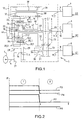
- the figure 1 shows a schematic representation of a transmission device 1 between an output 2 of a thermal engine 3 and a shaft 4 of wheels 5.
- the device 1 comprises a first electric machine 6 and a second electric machine 7.
- the machines 6 and 7 respectively comprise a shaft 8 and a shaft 9.
- the shafts 8 and 9 are respectively connected to a drive input 11.1 and 11.2 of a mechanical assembly 12 delimited by a discontinuous closed line.
- the device 1 also comprises an input shaft 10 connected to the output 2 of the thermal motor 3 and to a drive input 11.3 of the mechanical assembly 12.
- the device 1 also comprises an output shaft 14 connected both to the wheel shaft 4 and to an output 11.4 for driving the mechanical assembly 12.
- the electrical chain connecting the machines 6 and 7 electric between them is not shown.
- the mechanical assembly 12 comprises a train 16 called Ravigneaux type.
- the train 16 has four mechanical connecting elements: one for the input shaft 10, another for the output shaft 14 and the other two for the shafts 8 and 9 of the machines 6 and 7.
- the train 16 comprises a first sun gear 17, a planet carrier 18 carrying first satellites 19.1 and 19.2, and a ring gear 20 which mesh mutually.
- the train 16 comprises second satellites 21.1 and 21.2, and a second sun gear 22.
- the second satellites 21.1 and 21.2 are carried by the planet carrier 18 and mesh with both the first satellites 19.1 and 19.2 and with the sun gear. 22.
- the first train 65 comprises the first sun gear 17, the first satellites 19.1 and 19.2 and the ring gear 20.
- the second gear 66 comprises the second sun gear 22 and the second satellites 21.1 and 21.2, but is devoid of a ring gear.
- the two trains 65 and 66 comprise the common planet carrier 18.
- the planet carrier 18 common causes axes 23-26 which are both in contact with the planet carrier 18 and satellites 19.1, 19.2, 21.1 and 21.2.
- the satellites 19.1, 19.2, 21.1 and 21.2 are respectively capable of rotating around the axes 23, 24, 25 and 26.
- the satellites 19.1 and 21.1, and the satellites 19.2 and 21.2 may be interdependent and coaxial.
- the input shaft 10 is connected to both the output 2 of the thermal motor 3 and the planet carrier 18 common.
- the shaft 4 of wheels 5 is connected to the ring gear 20 by means of a gear train formed by the wheels 27 and 28, the output shaft 14 and a wheel 29. More specifically, the wheel 27 hooked to the shaft 4 meshes with the wheel 28 hooked at one end of the output shaft 14. And the wheel 29 hung on another end of the shaft 14 meshes with the ring 20.
- This ring 20 supports for this purpose two external teeth 20.1 and 20.2, and an internal toothing 20.3.
- the wheel 29 meshes with the external toothing 20.1.
- the first satellites 19.1 and 19.2 mesh with the internal teeth 20.3.
- a pinion 37 meshes with the external toothing 20.2.
- the shaft 8 of the first machine 6 is capable of being connected either to the second sun gear 22 or to the input shaft.
- the transmission device 1 comprises a first switching device 30 delimited by a discontinuous closed line.
- the first device 30 comprises the pinions 31 and 33 and two jaws 34, 35 distinct.
- the pinion 31 and the first clutch 34 are mounted on the shaft 8, while the pinion 33 and the second clutch 35 are mounted on the shaft 10.
- the first clutch 34 provides a connection between the pinion 31 and the shaft 8, while the pinion 33 is crazy on the shaft 10.
- the shaft 8 is then connected to the second sun gear 22 via a gear formed by the pinion 31 and the wheel 32, and a hollow shaft 48 connecting the wheel 32 to the sun gear 22.
- the second clutch 35 provides a connection between the pinion 33 and the shaft 10, while the pinion 31 is crazy on the shaft 8.
- the shaft 8 is thus connected to the shaft 10 via a gear formed by the wheel 13 and the pinion 33.
- the shaft 9 of the second machine 7 can be connected to either the wheel shaft 4 or the first sun gear 17.
- the device 1 comprises a second switching device 36.
- the second device 36 comprises the pinions 37, 38, and a third clutch 39 monobloc.
- the third clutch 39 provides a connection between the pinion 37 and the shaft 9, while the pinion 38 is crazy on the shaft 9.
- the shaft 9 is then connected to the shaft 4 by means in particular of the pinion 37, the ring 20 and the output shaft 14.
- the clutch 39 provides a connection between the pinion 38 and the shaft 9, while the pinion 37 is crazy on the shaft 9.
- the shaft 9 is then connected to the first planetary gear 17 via a gear formed by the pinion 38 and the wheel 40, and a hollow shaft 47 connecting the wheel 40 to the sun gear 17.
- the first device 30 comprises a one-piece clutch and is mounted only on the shaft 8.
- the second device 36 comprises two distinct claws mounted on the shaft 9.
- the claws 34, 35, 39 are rotated by the shaft on which they are mounted, and are able to move in translation along this shaft. In general, the claws are moved in translation through forks driven by a DC motor, not represented.
- the common planet carrier 18 and the ring gear 20 are connected to an oil pump 41 via a freewheel mechanism (not shown).
- the shafts 8 and 9, the input shaft 10 and the output shaft 5 are connected to different elements of the train 16.
- the figure 2 represents an evolution over time of the mechanical powers available at the various input and output shafts of the device.
- the clutch 34 provides a connection between the shaft 8 of the electric machine 6 and the pinion 31.
- the clutch 39 provides a connection between the shaft 9 of the electric machine 7 and the pinion 37.
- the first electrical machine 6 is for example linked in rotation to the second sun gear 22 and the second electric machine 7 is connected in rotation to the shaft 4 via the ring 20 and the output shaft 14.
- the first electrical machine 6 provides the device 1 a mechanical power P6 and the second electrical machine 7 provides the device 1 a mechanical power P7.
- the electric machine 6 operates in generator mode in the example shown and the power it provides to the device 1 is by negative agreement.
- the electric machine 7 operates in motor mode and the power it provides to the device 1 is positive.
- the heat engine 3 provides a power P3 to the device 1.
- the device 1 On the shaft 4, the device 1 provides a power P4 to the wheels 5.
- the power P4 is the sum of the powers received by the device namely P3, P6 and P7.
- Phase 10 is identical to phase 1 described above.
- Phase 11 when decoupling the electrical machine 7 from the shaft 4, it enters a phase 11 where it reduces to cancel the power P7 provided by the electric machine 7.
- the power P6 supplied by the electric machine 6 to the device 1 is increased so that the power P4 delivered by the device to the wheels 5 remains constant.
- a phase 12 begins at time t2 as a result of phase 11.
- the power supplied by the electric machine 7 remains zero, which allows its uncoupling and power P6 provided by the electric machine 6 remains constant, at the level where it was at the end of phase 11.
- the power P4 delivered by the device 1 to the wheels 5 remains constant.
- a change in the operating mode of the device 1 is often useful when the power that it is desired to deliver to the wheels 5 evolves.
- the method of the invention may be applied in the case where the curve representing the power P4 on the figure 3 evolves continuously over time.
- the modification of the power supplied by an electric machine is for example carried out by controlling a inverter placed between phases of the electric machine and a DC bus. There are reversible inverters for switching an electric machine from a generator mode to a motor mode and vice versa.
- the figure 4 represents a flowchart for changing the operating mode of the device 1.
- the electric machine 7 passes from a coupling to the shaft 4 to a coupling with the first sun gear 17. It is of course possible to implement this flowchart for the modification of the coupling of the electric machine 6.
- the torque cancellation command is materialized by step 50 and the verification of the cancellation of the torque is materialized by step 51.
- the cancellation of the torque is effective it is possible to enter the phase 12 and uncouple the shaft 4 from the electrical machine 7.
- the uncoupling is embodied by step 52.
- step 55 before coupling the electric machine 7 and the first sun gear 17, coupling materialized by step 55, by means of the dog clutch 39, it is necessary to synchronize the speed of rotation of the shaft 9 of the electric machine 7 with the speed of the first sun gear 17.
- the synchronization and the verification of this synchronization are materialized respectively by steps 53 and 54.
- the coupling is performed and the change of operating mode of the device becomes effective.
- the power transmitted by the electric machine 7 to the device 1 is zero.
- the end of the coupling is performed at time t3. From this moment, it is possible to modify the power level P6 supplied by the electric machine 6 as a function of an evolution of the power level P7 supplied by the electric machine 7 so that the power P4 delivered by the device 1 remains constant, as shown on the figure 5 , or linear.
- the modification of the powers P6 and P7 of the electrical machines 6 and 7 after coupling is illustrated by means of the figure 5 .
- This modification of the powers P6 and P7 provided by the two electrical machines 6 and 7 occurs in a phase 13 starting at time t3 and ending at a time t4.
- the phase 13 is followed by a phase 14 during which the powers P3, P6 and P7 supplied to the device 1 by the different sources, the electrical machines 6 and 7, and the heat engine 3 remain constant or possibly linear.
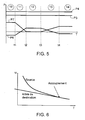
- the figure 6 represents the evolution over time of the speed of rotation w of a power source, for example of the electric machine 7, with respect to the speed of a destination tree, for example the first sun gear 17 to allow their coupling without risk for the dog concerned, in this case the clutch 39.
Landscapes
- Engineering & Computer Science (AREA)
- Mechanical Engineering (AREA)
- Transportation (AREA)
- Combustion & Propulsion (AREA)
- Chemical & Material Sciences (AREA)
- General Engineering & Computer Science (AREA)
- Power Engineering (AREA)
- Life Sciences & Earth Sciences (AREA)
- Automation & Control Theory (AREA)
- Sustainable Development (AREA)
- Sustainable Energy (AREA)
- Electric Propulsion And Braking For Vehicles (AREA)
- Control Of Transmission Device (AREA)
- Steroid Compounds (AREA)
- Radio Transmission System (AREA)
- Cable Transmission Systems, Equalization Of Radio And Reduction Of Echo (AREA)
Description
- L'invention concerne un procédé de transmission de puissance mettant en oeuvre un dispositif de transmission de puissance hybride multi mode. L'invention trouve une application particulièrement avantageuse dans le domaine des véhicules automobiles. Le dispositif de transmission reçoit de la puissance mécanique provenant de plusieurs sources comme par exemple un moteur thermique et plusieurs moteurs électriques et transmet cette puissance vers les roues motrices du véhicule.
- On connaît des dispositifs de transmission pour véhicules hybrides qui comportent un moteur thermique, deux machines électriques, et un, deux, ou plusieurs trains épicycloïdaux reliés entre eux à l'intérieur d'un ensemble mécanique. Un exemple d'un tel dispositif est décrit dans la demande de brevet français
FR-A-2832357 - La chaîne électrique relie les machines électriques susceptibles de se comporter en moteur ou en générateur selon des valeurs d'énergies reçues électriquement et / ou mécaniquement respectivement sur leurs bornes et leur arbre. La puissance dérivée est retransmise aux roues du véhicule ou stockée, le cas échéant, dans un système de stockage. Cette puissance dérivée permet d'adapter précisément le couple appliqué aux roues du véhicule à celui demandé par un conducteur, tout en adaptant également précisément les couple et régime du moteur thermique de façon à optimiser son rendement.
- En outre, la chaîne électrique comporte notamment un premier onduleur, un deuxième onduleur, ainsi qu'un bus électrique. Dans la pratique, ce bus électrique est un bus à tension continue.
- Lorsqu'une des machines électriques se comporte en générateur, les signaux de tension alternative observables entre ses phases sont transformés en un signal de tension continue observable sur le bus, par l'onduleur associé à cette machine. Lorsqu'une des machines se comporte en moteur, le signal de tension continue observable sur le bus est transformé en signaux de tension alternative et déphasés par l'onduleur associé à cette machine. Ces signaux de tension sont appliqués sur les phases de la machine qui fonctionne en moteur. Dans le cas où aucun système de stockage n'est relié au bus, l'énergie produite par une des machines est automatiquement consommée par l'autre machine. En variante, un système de stockage, tel qu'une batterie ou un super condensateur, est relié au bus. Les deux machines peuvent alors fonctionner simultanément en générateur ou en moteur.
- Dans le document
FR-A-2832357 - Les passages d'un mode de fonctionnement à l'autre se font en désaccouplant une machine électrique d'un arbre de départ puis en réaccouplant cette même machine à un arbre de destination. On désaccouple par exemple une machine électrique de l'arbre de roues pour la réaccoupler à un élément des trains épicycloïdaux.
- On se place dans le cas général où l'arbre de départ et l'arbre de destination ont des régimes différents. Il n'est par conséquent pas envisageable de lier la machine électrique sur les arbres de départ et de destination en même temps. Il est donc nécessaire de passer par une phase intermédiaire dans laquelle la machine électrique n'est plus liée à la transmission (liée ni à l'arbre de départ, ni à l'arbre de destination). Durant cette phase intermédiaire, la machine électrique ne fournit aucune puissance aux roues du véhicule. Ceci entraîne une modification de la puissance de sortie du dispositif de transmission et donc du couple transmis aux roues du véhicule.
- L'invention vise à pallier ce problème en proposant un nouveau procédé de transmission de puissance dans lequel au cours du changement de mode de fonctionnement du dispositif, la puissance de sortie du dispositif reste linéaire. Par puissance restant linéaire, on entend une évolution de la valeur de la puissance sans à-coup. En première approximation, on peut considérer que la puissance de sortie reste sensiblement constante durant le changement de mode de fonctionnement du dispositif.
- A cet effet, l'invention a pour objet un procédé de transmission de puissance dans lequel on met en oeuvre un dispositif de transmission recevant de la puissance mécanique provenant de plusieurs sources, comportant au moins une première et une deuxième machines électriques, et délivrant la puissance vers un arbre de sortie, le procédé consistant à désaccoupler la première machine électrique d'un premier point d'entrée du dispositif, puis à accoupler la première machine électrique à un second point d'entrée du dispositif, le procédé consistant, en outre, durant le désaccouplement de la première machine électrique, à compenser la puissance transmise par la première machine électrique avant son désaccouplement en modifiant la puissance transmise par la deuxième machine électrique des sources de façon à ce que la puissance délivrée par le dispositif reste linéaire. Le procédé selon l'invention est caractérisé en ce qu'il consiste à enchaîner les phases suivantes :
- annulation du couple fourni au dispositif par la première machine électrique,
- désaccouplement de la première machine électrique ;
- Dans un mode de réalisation où trois sources de puissances dont un moteur thermique et deux machines électriques sont mises en oeuvre, le dispositif selon l'invention permet de modifier l'accouplement d'au moins une des machines électriques. Il est possible durant la période où une des machines électriques est désaccouplée, de modifier la puissance fournie par le moteur thermique pour conserver la linéarité de la puissance délivrée par le dispositif. Mais dans une variante préférée où les sources comportent au moins deux machines électriques, le procédé consiste à désaccoupler puis réaccoupler une première des machines électriques et à modifier la puissance fournie par la deuxième des machines électriques. Il est en effet généralement plus aisé de modifier la puissance fournie par une machine électrique que par le moteur thermique.
- synchronisation de la première machine électrique avec le second point d'entrée du dispositif ;
- accouplement de la première machine électrique au second point d'entrée,
- Il est possible de compléter le procédé après l'accouplement de la première machine électrique au second point d'entrée, en modifiant le niveau de puissance fourni par la deuxième machine électrique dont la puissance a été modifiée en fonction d'un niveau de puissance fourni par la première machine électrique au second point d'entrée de manière à ce que la puissance délivrée par le dispositif reste linéaire.
- L'invention sera mieux comprise et d'autres avantages apparaîtront à la lecture de la description détaillée d'un mode de réalisation donné à titre d'exemple, description illustrée par le dessin joint dans lequel :
- la
figure 1 représente schématiquement un dispositif de transmission pour lequel l'invention peut être mise en oeuvre ; - les
figures 2 ,3 et5 représentent une évolution dans le temps des puissances mécaniques disponibles au niveau des différents arbres d'entrée et de sortie du dispositif de lafigure 1 ; - la
figure 4 représente un organigramme de changement de mode de fonctionnement du dispositif 1 ; - et la
figure 6 représente l'évolution dans le temps des vitesses de rotation d'une source de puissance par rapport à un arbre de destination. - Par souci de clarté, les mêmes éléments porteront les mêmes repères dans les différentes figures.
- La
figure 1 montre une représentation schématique d'un dispositif 1 de transmission entre une sortie 2 d'un moteur 3 thermique et un arbre 4 de roues 5. - Le dispositif 1 comporte une première machine 6 électrique et une deuxième machine 7 électrique. Les machines 6 et 7 comportent respectivement un arbre 8 et un arbre 9. Les arbres 8 et 9 sont respectivement reliés à une entrée 11.1 et 11.2 d'entraînement d'un ensemble 12 mécanique délimité par une ligne fermée discontinue. Le dispositif 1 comporte également un arbre 10 d'entrée relié à la sortie 2 du moteur 3 thermique et à une entrée 11.3 d'entraînement de l'ensemble 12 mécanique. Le dispositif 1 comporte également un arbre 14 de sortie relié à la fois à l'arbre 4 de roues 5 et à une sortie 11.4 d'entraînement de l'ensemble 12 mécanique. Pour plus de simplicité, la chaîne électrique reliant les machines 6 et 7 électriques entre elles n'est pas représentée.
- Plus précisément, l'ensemble 12 mécanique comporte un train 16 dit de type Ravigneaux. Le train 16 présente quatre éléments de liaison mécanique : un pour l'arbre 10 d'entrée, un autre pour l'arbre 14 de sortie et les deux autres pour les arbres 8 et 9 des machines 6 et 7. Comme un train épicycloïdal classique, Le train 16 comporte un premier planétaire 17, un porte-satellites 18 portant des premiers satellites 19.1 et 19.2, et une couronne 20 qui engrènent mutuellement. En outre, le train 16 comporte des deuxièmes satellites 21.1 et 21.2, et un deuxième planétaire 22. Les deuxièmes satellites 21.1 et 21.2 sont portés par le porte-satellites 18 et engrènent à la fois avec les premiers satellites 19.1 et 19.2 et avec le planétaire 22.
- On peut ainsi faire l'analogie du train 16 Ravigneaux avec deux trains 65 et 66 épicycloïdaux. Le premier train 65 comporte le premier planétaire 17, les premiers satellites 19.1 et 19.2 et la couronne 20. Le deuxième train 66 comporte le deuxième planétaire 22 et les deuxièmes satellites 21.1 et 21.2, mais est dépourvu de couronne. Les deux trains 65 et 66 comportent le porte-satellites 18 commun. Le porte-satellites 18 commun entraîne des axes 23-26 qui sont à la fois au contact du porte-satellites 18 et des satellites 19.1, 19.2, 21.1 et 21.2. Les satellites 19.1, 19.2, 21.1 et 21.2 sont respectivement susceptibles de tourner autour des axes 23, 24, 25 et 26. En variante, comme on le verra ci-après, les satellites 19.1 et 21.1, et les satellites 19.2 et 21.2 peuvent être solidaires entre eux et coaxiaux.
- Dans ce mode de réalisation, l'arbre 10 d'entrée est relié à la fois à la sortie 2 du moteur 3 thermique et au porte-satellites 18 commun. L'arbre 4 de roues 5 est relié à la couronne 20 par l'intermédiaire d'un train d'engrenage formé par les roues 27 et 28, de l'arbre 14 de sortie et d'une roue 29. Plus précisément, la roue 27 accrochée à l'arbre 4 engrène avec la roue 28 accrochée à une extrémité de l'arbre 14 de sortie. Et la roue 29 accrochée à une autre extrémité de l'arbre 14 engrène avec la couronne 20.
- Cette couronne 20 supporte à cet effet deux dentures extérieures 20.1 et 20.2, et une denture intérieure 20.3. La roue 29 engrène avec la denture extérieure 20.1. Les premiers satellites 19.1 et 19.2 engrènent avec la denture intérieure 20.3. Et comme on le verra ci-après, un pignon 37 engrène avec la denture extérieure 20.2.
- L'arbre 8 de la première machine 6 est susceptible d'être relié soit au deuxième planétaire 22, soit à l'arbre 10 d'entrée. A cet effet, le dispositif 1 de transmission comporte un premier dispositif 30 de commutation délimité par une ligne fermée discontinue. Le premier dispositif 30 comporte les pignons 31 et 33 et deux crabots 34, 35 distincts. Le pignon 31 et le premier crabot 34 sont montés sur l'arbre 8, tandis que le pignon 33 et le deuxième crabot 35 sont montés sur l'arbre 10.
- Ainsi, lorsque l'arbre 8 est relié au deuxième planétaire 22, le premier crabot 34 assure une liaison entre le pignon 31 et l'arbre 8, tandis que le pignon 33 est fou sur l'arbre 10. L'arbre 8 est alors relié au deuxième planétaire 22 par l'intermédiaire d'un engrenage formé par le pignon 31 et la roue 32, et d'un arbre 48 creux reliant la roue 32 au planétaire 22. Lorsque l'arbre 8 est relié à l'arbre 10 d'entrée, le deuxième crabot 35 assure une liaison entre le pignon 33 et l'arbre 10, tandis que le pignon 31 est fou sur l'arbre 8. L'arbre 8 est ainsi relié à l'arbre 10 par l'intermédiaire d'un engrenage formé par la roue 13 et le pignon 33.
- L'arbre 9 de la deuxième machine 7 est susceptible d'être relié soit à l'arbre 4 de roues 5, soit au premier planétaire 17. A cet effet, le dispositif 1 comporte un deuxième dispositif 36 de commutation. Le deuxième dispositif 36 comporte les pignons 37, 38, ainsi qu'un troisième crabot 39 monobloc.
- Lorsque l'arbre 9 est relié à l'arbre 4 de roues 5, le troisième crabot 39 assure une liaison entre le pignon 37 et l'arbre 9, tandis que le pignon 38 est fou sur l'arbre 9. L'arbre 9 est alors relié à l'arbre 4 par l'intermédiaire notamment du pignon 37, de la couronne 20 et de l'arbre 14 de sortie. Lorsque l'arbre 9 est relié au premier planétaire 17, le crabot 39 assure une liaison entre le pignon 38 et l'arbre 9, tandis que le pignon 37 est fou sur l'arbre 9. L'arbre 9 est alors relié au premier planétaire 17 par l'intermédiaire d'un engrenage formé par le pignon 38 et la roue 40, et d'un arbre 47 creux reliant la roue 40 au planétaire 17.
- En variante, le premier dispositif 30 comporte un crabot monobloc et est monté uniquement sur l'arbre 8. Selon une autre variante, le deuxième dispositif 36 comporte deux crabots distincts montés sur l'arbre 9.
- Les crabots 34, 35, 39 sont entraînés en rotation par l'arbre sur lequel ils sont montés, et sont capables de se déplacer en translation le long de cet arbre. En général, les crabots sont déplacés en translation par l'intermédiaire de fourchettes entraînées par un moteur à courant continu, non réprésentées.
- Dans un mode de réalisation particulier, le porte-satellites 18 commun et la couronne 20 sont reliés à une pompe 41 à huile, par l'intermédiaire d'un mécanisme de roue libre (non représenté).
- En variante, les arbres 8 et 9, l'arbre 10 d'entrée et l'arbre 14 de sortie 5 sont reliés à des éléments différents du train 16.
- La
figure 2 représente une évolution dans le temps des puissances mécaniques disponibles au niveau des différents arbres d'entrée et de sortie du dispositif. On considère un état du dispositif de transmission 1 dans lequel le crabot 34 assure une liaison entre l'arbre 8 de la machine électrique 6 et le pignon 31. Le crabot 39 assure une liaison entre l'arbre 9 de la machine électrique 7 et le pignon 37. Dans une première phase ① la première machine électrique 6 est par exemple liée en rotation au deuxième planétaire 22 et la deuxième machine électrique 7 est liée en rotation à l'arbre 4 par l'intermédiaire de la couronne 20 et de l'arbre de sortie 14. La première machine électrique 6 fournit au dispositif 1 une puissance mécanique P6 et la deuxième machine électrique 7 fournit au dispositif 1 une puissance mécanique P7. La machine électrique 6 fonctionne en mode générateur dans l'exemple représenté et la puissance qu'elle fournit au dispositif 1 est par convention négative. La machine électrique 7 fonctionne en mode moteur et la puissance qu'elle fournit au dispositif 1 est donc positive. Le moteur thermique 3 fournit quant à lui une puissance P3 au dispositif 1. Sur l'arbre 4, le dispositif 1 fournit une puissance P4 aux roues 5. La puissance P4 est la somme des puissances reçues par le dispositif à savoir P3, P6 et P7. - A un instant t, on décide de désaccoupler la machine électrique 7 de l'arbre 4. Pour se faire, on annule la puissance P7 fournie par la machine électrique 7 au dispositif 1 avant de réaliser le désaccouplement Le désaccouplement peut être effectué lors d'une phase repérée ② sur la
figure 2 . Dans cette nouvelle phase, les puissances P3 et P6 fournies au dispositif 1 par la machine électrique 6 et par le moteur thermique 3 sont identiques aux puissances fournies lors de la phase ①. En conséquence, la puissance P4 fournie aux roues 5 a chutée. - Sur la
figure 3 , le procédé selon l'invention est mis en oeuvre pour éviter la chutte de puissance observée sur lafigure 2 . La phase ⑩ est identique à la phase ① décrite précédemment. A un instant t1, lorsqu'on décide de désaccoupler la machine électrique 7 de l'arbre 4, on entre dans une phase ⑪ où on réduit jusqu'à annuler la puissance P7 fournie par la machine électrique 7. Pendant cette même phase ⑪, on augmente la puissance P6 fournie par la machine électrique 6 au dispositif 1 de façon à ce que la puissance P4 délivrée par le dispositif aux roues 5 reste constante. Une phase ⑫ débute à l'instant t2 à la suite de la phase ⑪. Durant la phase ⑫ la puissance fournie par la machine électrique 7 reste nulle, ce qui permet son désaccouplement et la puissance P6 fournie par la machine électrique 6 reste constante, au niveau où elle se situait en fin de phase ⑪. Dans l'exemple illustré par lafigure 3 , la puissance P4 délivrée par le dispositif 1 aux roues 5 reste constante. En pratique, un changement de mode de fonctionnement du dispositif 1, est souvent utile lorsque la puissance que l'on souhaite délivrer aux roues 5 évolue. Mais pour un confort de conduite d'un véhicule équipé du dispositif 1, et pour éviter de trop solliciter les différents organes mécaniques par lesquels transite la puissance fournie aux roues 5, il est important que l'évolution de la puissance fournie aux roues 5 évolue sans à-coup. On peut par exemple appliquer le procédé de l'invention dans le cas où la courbe représentant la puissance P4 sur lafigure 3 évolue de façon continûment croissante dans le temps. - Pour mettre en oeuvre l'invention, on pourrait également modifier la puissance P3 fournie au dispositif 1 par le moteur thermique 3. Mais il est en général plus aisé de modifier la puissance d'un moteur électrique que la puissance d'un moteur thermique. La modification de la puissance fournie par une machine électrique est par exemple réalisée en commandant un onduleur placé entre des phases de la machine électrique et un bus à courant continu. Il existe des onduleurs réversibles permettant de passer, pour une machine électrique, d'un mode générateur à un mode moteur et inversement.
- La
figure 4 représente un organigramme de changement de mode de fonctionnement du dispositif 1. Au cours de ce changement, la machine électrique 7 passe d'un accouplement à l'arbre 4 à un accouplement au premier planétaire 17. Il est bien entendu possible de mettre en oeuvre cet organigramme pour la modification de l'accouplement de la machine électrique 6. A un instant t1, lorsqu'on décide de désaccoupler la machine électrique 7 de l'arbre 4, il est nécessaire d'annuler le couple produit par la machine électrique 7 au niveau de son arbre 9 avant de procéder au désaccouplement La commande d'annulation du couple est matérialisée par l'étape 50 et la vérification de l'annulation du couple est matérialisée par l'étape 51. Lorsque l'annulation du couple est effective, on peut entrer dans la phase ⑫ et désaccoupler l'arbre 4 de la machine électrique 7. Le désaccouplement est matérialisé par l'étape 52. Ensuite avant de procéder à l'accouplement de la machine électrique 7 et du premier planétaire 17, accouplement matérialisé par l'étape 55, au moyen du crabot 39, il est nécessaire de synchroniser la vitesse de rotation de l'arbre 9 de la machine électrique 7 avec la vitesse du premier planétaire 17. la synchronisation et la vérification de cette synchronisation sont matérialisées respectivement par les étapes 53 et 54. A l'issue de la synchronisation, l'accouplement est réalisé et le changement de mode de fonctionnement du dispositif devient effectif. - Au moment de l'accouplement de la machine électrique 7 et du premier planétaire 17, la puissance transmise par la machine électrique 7 au dispositif 1 est nulle. La fin de l'accouplement est réalisée à l'instant t3. A partir de cet instant, il est possible de modifier le niveau de puissance P6 fourni par la machine électrique 6 en fonction d'une évolution du niveau de puissance P7 fourni par la machine électrique 7 de manière à ce que la puissance P4 délivrée par le dispositif 1 reste constante, comme représenté sur la
figure 5 , ou encore linéaire. La modification des puissances P6 et P7 des machines électriques 6 et 7 après accouplement est illustée à l'aide de lafigure 5 . Cette modification des puissances P6 et P7 fournies par les deux machines électriques 6 et 7 intervient dans une phase ⑬ commençant à l'instant t3 et se terminant à un instant t4. La phase ⑬ est suivie d'une phase ⑭ pendant laquelle les puissances P3, P6 et P7 fournies au dispositif 1 par les différentes sources, machines électriques 6 et 7, et moteur thermique 3 restent constantes ou éventuellement linéaires. - La
figure 6 représente l'évolution dans le temps de la vitesse de rotation w d'une source de puissance, par exemple de la machine électrique 7, par rapport à la vitesse d'un arbre de destination, par exemple le premier planétaire 17 pour permettre leur accouplement sans risque pour le crabot concerné, en l'occurrence le crabot 39.
Claims (3)
- Procédé de transmission de puissance dans lequel on met en oeuvre un dispositif (1) de transmission recevant de la puissance mécanique provenant de plusieurs sources (3, 6, 7), comportant au moins une première et une deuxième machines électriques (6, 7), et délivrant la puissance vers un arbre (4) de sortie, le procédé consistant à désaccoupler la première machine électrique (7) d'un premier point d'entrée (4) du dispositif (1), puis à accoupler la première machine électrique (7) à un second point d'entrée (17) du dispositif (1), le procédé consistant, en outre, durant le désaccouplement de la première machine électrique (7), à compenser la puissance (P7) transmise par la première machine électrique (7) avant son désaccouplement en modifiant la puissance (P6) transmise par la deuxième machine électrique (6) des sources de façon à ce que la puissance (P4) délivrée par le dispositif (1) reste linéaire, caractérisé en ce qu'il consiste à enchaîner les phases suivantes :- annulation du couple fourni au dispositif (1) par la première machine électrique (7) ;- désaccouplement de la première machine électrique (7) ;- synchronisation de la première machine électrique (7) avec le second point (17) d'entrée du dispositif (1) ;- accouplement de la première machine électrique (7) au second point (17) d'entrée ;et en ce que lors de l'annulation du couple, la puissance (P6) de la deuxième machine électrique (6), reliée au dispositif (1), est modifiée.
- Procédé selon la revendication 1, caractérisé en ce que le procédé consiste à désaccoupler puis réaccoupler la première machine électrique (7) et à modifier la puissance (P6) fournie par la deuxième machine électrique (6).
- Procédé selon la revendication 2, caractérisé en ce qu'il consiste, après l'accouplement de la première machine électrique (7) au second point d'entrée (17), à modifier le niveau de puissance fourni par la deuxième machine électrique (6) dont la puissance (P6) a été adaptée en fonction d'un niveau de puissance (P7) fourni par la première machine électrique (7) au second point (17) d'entrée de manière à ce que la puissance (P4) délivrée par le dispositif (1) reste linéaire.
Applications Claiming Priority (2)
| Application Number | Priority Date | Filing Date | Title |
|---|---|---|---|
| FR0603001A FR2899548B1 (fr) | 2006-04-05 | 2006-04-05 | Procede de transmission de puissance |
| PCT/FR2007/051034 WO2007113438A1 (fr) | 2006-04-05 | 2007-03-28 | Procede de transmission de puissance |
Publications (2)
| Publication Number | Publication Date |
|---|---|
| EP2001719A1 EP2001719A1 (fr) | 2008-12-17 |
| EP2001719B1 true EP2001719B1 (fr) | 2010-08-18 |
Family
ID=37487618
Family Applications (1)
| Application Number | Title | Priority Date | Filing Date |
|---|---|---|---|
| EP07731840A Not-in-force EP2001719B1 (fr) | 2006-04-05 | 2007-03-28 | Procede de transmission de puissance |
Country Status (7)
| Country | Link |
|---|---|
| US (1) | US20090166107A1 (fr) |
| EP (1) | EP2001719B1 (fr) |
| JP (1) | JP5232137B2 (fr) |
| AT (1) | ATE477979T1 (fr) |
| DE (1) | DE602007008538D1 (fr) |
| FR (1) | FR2899548B1 (fr) |
| WO (1) | WO2007113438A1 (fr) |
Families Citing this family (16)
| Publication number | Priority date | Publication date | Assignee | Title |
|---|---|---|---|---|
| JPH0717244B2 (ja) | 1986-04-30 | 1995-03-01 | 富士電機株式会社 | 集品装置 |
| JPH0717245B2 (ja) | 1986-05-28 | 1995-03-01 | 富士電機株式会社 | 集品装置 |
| JPH0761812B2 (ja) | 1988-05-20 | 1995-07-05 | オークラ輸送機株式会社 | 搬送仕分け方法 |
| FR2884766B1 (fr) * | 2005-04-26 | 2008-11-28 | Peugeot Citroen Automobiles Sa | Dispositif de transmission de puissance d'un vehicule automobile muni d'un mecanisme a roues libres entrainant une pompe a huile |
| DE102011114231B4 (de) | 2010-09-30 | 2024-04-25 | GM Global Technology Operations LLC (n. d. Gesetzen des Staates Delaware) | Doppelantriebspumpensystem |
| JP6032290B2 (ja) * | 2012-12-12 | 2016-11-24 | トヨタ自動車株式会社 | ハイブリッド車両 |
| SE1350394A1 (sv) * | 2013-03-27 | 2014-09-28 | Scania Cv Ab | Växellåda, fordon med en sådan växellåda, förfarande för attstyra en sådan växellåda, datorprogram för att styra en sådan växellåda, samt en datorprogramprodukt innefattande programkod |
| SE1350393A1 (sv) * | 2013-03-27 | 2014-09-28 | Scania Cv Ab | Växellåda, fordon med en sådan växellåda, förfarande för attstyra en sådan växellåda, datorprogram för att styra en sådan växellåda, samt en datorprogramprodukt innefattande programkod |
| US10604142B2 (en) | 2013-12-23 | 2020-03-31 | Scania Cv Ab | Method for control of a propulsion system of a vehicle, a propulsion system, a computer program product and a vehicle |
| WO2015099602A1 (fr) | 2013-12-23 | 2015-07-02 | Scania Cv Ab | Système de traction pour un véhicule |
| US10246082B2 (en) | 2013-12-23 | 2019-04-02 | Scania Cv Ab | Propulsion system for a vehicle |
| US9937920B2 (en) | 2013-12-23 | 2018-04-10 | Scania Cv Ab | Propulsion system for a vehicle |
| US10266172B2 (en) | 2013-12-23 | 2019-04-23 | Scania Cv Ab | Propulsion system for a vehicle |
| US11181174B2 (en) | 2019-11-07 | 2021-11-23 | Hyundai Motor Company | Powertrain for electric vehicle |
| US11927253B2 (en) | 2019-11-07 | 2024-03-12 | Hyundai Motor Company | Powertrain for electric vehicle |
| KR102424448B1 (ko) * | 2020-11-03 | 2022-07-22 | 현대자동차주식회사 | Amt 차량의 변속 제어방법 |
Family Cites Families (14)
| Publication number | Priority date | Publication date | Assignee | Title |
|---|---|---|---|---|
| GB9700960D0 (en) * | 1997-01-17 | 1997-03-05 | Rover Group | Hybrid vehicle powertrain control |
| JPH10243502A (ja) * | 1997-02-26 | 1998-09-11 | Aisin Aw Co Ltd | 車両用駆動装置の制御装置 |
| JP3368816B2 (ja) * | 1997-12-05 | 2003-01-20 | 日産自動車株式会社 | ハイブリッド車の制御装置 |
| JP3336951B2 (ja) * | 1998-04-28 | 2002-10-21 | 株式会社日立製作所 | 自動車の動力伝達装置 |
| JP3494008B2 (ja) * | 1998-05-07 | 2004-02-03 | トヨタ自動車株式会社 | 動力出力装置およびその制御方法 |
| JP3454172B2 (ja) * | 1998-11-04 | 2003-10-06 | 日産自動車株式会社 | ハイブリッド車両の制御方法 |
| JP2000224714A (ja) * | 1999-02-03 | 2000-08-11 | Mitsubishi Motors Corp | 電動機付車両 |
| JP3515006B2 (ja) * | 1999-02-23 | 2004-04-05 | 本田技研工業株式会社 | ハイブリッド車両の制御装置 |
| US6319168B1 (en) * | 2000-04-25 | 2001-11-20 | General Motors Corporation | Apparatus and method for active transmission synchronization and shifting |
| JP3573202B2 (ja) * | 2000-11-06 | 2004-10-06 | 三菱自動車工業株式会社 | ハイブリッド車両のトルク制御装置 |
| JP3638876B2 (ja) * | 2001-03-01 | 2005-04-13 | 株式会社日立製作所 | 車両の駆動装置及び車両 |
| JP4743992B2 (ja) * | 2001-04-23 | 2011-08-10 | トヨタ自動車株式会社 | 車両の制御装置 |
| FR2832357B1 (fr) * | 2001-11-21 | 2004-02-27 | Peugeot Citroen Automobiles Sa | Dispositif de transmission de puissance a au moins deux trains epicycloidaux |
| JP2004161053A (ja) * | 2002-11-11 | 2004-06-10 | Nissan Motor Co Ltd | ハイブリッド車両の駆動装置 |
-
2006
- 2006-04-05 FR FR0603001A patent/FR2899548B1/fr not_active Expired - Fee Related
-
2007
- 2007-03-28 JP JP2009503626A patent/JP5232137B2/ja not_active Expired - Fee Related
- 2007-03-28 WO PCT/FR2007/051034 patent/WO2007113438A1/fr not_active Ceased
- 2007-03-28 AT AT07731840T patent/ATE477979T1/de not_active IP Right Cessation
- 2007-03-28 EP EP07731840A patent/EP2001719B1/fr not_active Not-in-force
- 2007-03-28 DE DE602007008538T patent/DE602007008538D1/de active Active
- 2007-03-28 US US12/296,102 patent/US20090166107A1/en not_active Abandoned
Also Published As
| Publication number | Publication date |
|---|---|
| US20090166107A1 (en) | 2009-07-02 |
| FR2899548B1 (fr) | 2009-04-17 |
| JP5232137B2 (ja) | 2013-07-10 |
| DE602007008538D1 (de) | 2010-09-30 |
| JP2009532271A (ja) | 2009-09-10 |
| EP2001719A1 (fr) | 2008-12-17 |
| FR2899548A1 (fr) | 2007-10-12 |
| ATE477979T1 (de) | 2010-09-15 |
| WO2007113438A1 (fr) | 2007-10-11 |
Similar Documents
| Publication | Publication Date | Title |
|---|---|---|
| EP2001719B1 (fr) | Procede de transmission de puissance | |
| EP1877273B1 (fr) | Dispositif de commutation pour vehicule automobile et utilisation de ce dispositif | |
| EP2694309B2 (fr) | Transmission hybride pour vehicule automobile et procede de commande | |
| EP1875104B1 (fr) | Dispositif de transmission de puissance d'un vehicule automobile muni d'un mecanisme a roues libres entrainant une pompe a huile | |
| EP1097830B1 (fr) | Groupe motopropulseur hybride comportant au moins deux trains épicycloidaux | |
| EP3581416B1 (fr) | Dispositif de transmission, notamment pour véhicule électrique | |
| FR2832357A1 (fr) | Dispositif de transmission de puissance a au moins deux trains epicycloidaux | |
| WO2016092184A1 (fr) | Transmission automatique pour véhicule hybride et procédé de commande d'un véhicule hybride | |
| EP2209660B1 (fr) | Dispositif de transmission de puissance entre une sortie d'un moteur thermique et un arbre de roues et utilisation de ce dispositif | |
| WO2011148065A1 (fr) | Boite de vitesses a double embrayage comportant une liaison de transfert et un rapport de marche arriere | |
| WO2006032819A1 (fr) | Dispositif de transmission de puissance et procede mettant en oeuvre ce dispositif | |
| FR3021592A1 (fr) | Transmission automatique pour vehicule hybride | |
| FR2933247A1 (fr) | Procede d'accouplement pour vehicule electrique ou hybride entre un arbre d'une machine electrique et un arbre de roues | |
| EP1910117A1 (fr) | Procede de blocage de roues d'un vehicule hybride a l'arret et dispositif de transmission associe | |
| WO2006100404A1 (fr) | Dispositif de transmission de puissance entre une sortie d'un moteur thermique et un arbre de roues et procede de transmission de puissance associe | |
| EP4094963A1 (fr) | Sous-ensemble hybride d'entraînement d'un véhicule, groupe moteur hybride et procédé d'entraînement hybride | |
| WO2019122553A1 (fr) | Chaîne de traction améliorée de véhicule automobile comprenant deux machines électriques tournantes | |
| WO2021170523A1 (fr) | Module motorisé, sous-ensemble hybride d'entrainement d'un véhicule, et méthode d'engagement d'un crabot dans ledit sous-ensemble hybride | |
| EP1789722B1 (fr) | Dispositif de transmission de puissance pour vehicule automobile et procede d'utilisation de ce dispositif | |
| EP1792101B1 (fr) | Dispositif de transmission de puissance dans un vehicule entre un arbre d'un moteur thermique et un arbre de roues | |
| EP1832460B1 (fr) | Dispositif de transmission de puissance et procédé mettant en oeuvre ce dispositif | |
| FR2967620A1 (fr) | Vehicule hybride a deux trains d'engrenages epicycloidaux a derivation de puissance et a efficacite energetique amelioree | |
| FR3077536A1 (fr) | Dispositif de transmission a deux vitesses pour vehicule electrique | |
| EP3215381B1 (fr) | Système d'entraînement d'un véhicule hybride | |
| FR3056157A1 (fr) | Systeme de transmission de puissance pour vehicule automobile |
Legal Events
| Date | Code | Title | Description |
|---|---|---|---|
| PUAI | Public reference made under article 153(3) epc to a published international application that has entered the european phase |
Free format text: ORIGINAL CODE: 0009012 |
|
| 17P | Request for examination filed |
Effective date: 20080922 |
|
| AK | Designated contracting states |
Kind code of ref document: A1 Designated state(s): AT BE BG CH CY CZ DE DK EE ES FI FR GB GR HU IE IS IT LI LT LU LV MC MT NL PL PT RO SE SI SK TR |
|
| 17Q | First examination report despatched |
Effective date: 20090220 |
|
| GRAP | Despatch of communication of intention to grant a patent |
Free format text: ORIGINAL CODE: EPIDOSNIGR1 |
|
| DAX | Request for extension of the european patent (deleted) | ||
| GRAS | Grant fee paid |
Free format text: ORIGINAL CODE: EPIDOSNIGR3 |
|
| GRAA | (expected) grant |
Free format text: ORIGINAL CODE: 0009210 |
|
| AK | Designated contracting states |
Kind code of ref document: B1 Designated state(s): AT BE BG CH CY CZ DE DK EE ES FI FR GB GR HU IE IS IT LI LT LU LV MC MT NL PL PT RO SE SI SK TR |
|
| REG | Reference to a national code |
Ref country code: GB Ref legal event code: FG4D Free format text: NOT ENGLISH |
|
| REG | Reference to a national code |
Ref country code: CH Ref legal event code: EP |
|
| REG | Reference to a national code |
Ref country code: IE Ref legal event code: FG4D Free format text: LANGUAGE OF EP DOCUMENT: FRENCH |
|
| REF | Corresponds to: |
Ref document number: 602007008538 Country of ref document: DE Date of ref document: 20100930 Kind code of ref document: P |
|
| REG | Reference to a national code |
Ref country code: GB Ref legal event code: 746 Effective date: 20101006 |
|
| REG | Reference to a national code |
Ref country code: NL Ref legal event code: VDEP Effective date: 20100818 |
|
| LTIE | Lt: invalidation of european patent or patent extension |
Effective date: 20100818 |
|
| PG25 | Lapsed in a contracting state [announced via postgrant information from national office to epo] |
Ref country code: AT Free format text: LAPSE BECAUSE OF FAILURE TO SUBMIT A TRANSLATION OF THE DESCRIPTION OR TO PAY THE FEE WITHIN THE PRESCRIBED TIME-LIMIT Effective date: 20100818 Ref country code: FI Free format text: LAPSE BECAUSE OF FAILURE TO SUBMIT A TRANSLATION OF THE DESCRIPTION OR TO PAY THE FEE WITHIN THE PRESCRIBED TIME-LIMIT Effective date: 20100818 Ref country code: LT Free format text: LAPSE BECAUSE OF FAILURE TO SUBMIT A TRANSLATION OF THE DESCRIPTION OR TO PAY THE FEE WITHIN THE PRESCRIBED TIME-LIMIT Effective date: 20100818 |
|
| PG25 | Lapsed in a contracting state [announced via postgrant information from national office to epo] |
Ref country code: SI Free format text: LAPSE BECAUSE OF FAILURE TO SUBMIT A TRANSLATION OF THE DESCRIPTION OR TO PAY THE FEE WITHIN THE PRESCRIBED TIME-LIMIT Effective date: 20100818 Ref country code: PT Free format text: LAPSE BECAUSE OF FAILURE TO SUBMIT A TRANSLATION OF THE DESCRIPTION OR TO PAY THE FEE WITHIN THE PRESCRIBED TIME-LIMIT Effective date: 20101220 Ref country code: PL Free format text: LAPSE BECAUSE OF FAILURE TO SUBMIT A TRANSLATION OF THE DESCRIPTION OR TO PAY THE FEE WITHIN THE PRESCRIBED TIME-LIMIT Effective date: 20100818 Ref country code: IS Free format text: LAPSE BECAUSE OF FAILURE TO SUBMIT A TRANSLATION OF THE DESCRIPTION OR TO PAY THE FEE WITHIN THE PRESCRIBED TIME-LIMIT Effective date: 20101218 Ref country code: CY Free format text: LAPSE BECAUSE OF FAILURE TO SUBMIT A TRANSLATION OF THE DESCRIPTION OR TO PAY THE FEE WITHIN THE PRESCRIBED TIME-LIMIT Effective date: 20100818 Ref country code: BG Free format text: LAPSE BECAUSE OF FAILURE TO SUBMIT A TRANSLATION OF THE DESCRIPTION OR TO PAY THE FEE WITHIN THE PRESCRIBED TIME-LIMIT Effective date: 20101118 |
|
| REG | Reference to a national code |
Ref country code: IE Ref legal event code: FD4D |
|
| PG25 | Lapsed in a contracting state [announced via postgrant information from national office to epo] |
Ref country code: LV Free format text: LAPSE BECAUSE OF FAILURE TO SUBMIT A TRANSLATION OF THE DESCRIPTION OR TO PAY THE FEE WITHIN THE PRESCRIBED TIME-LIMIT Effective date: 20100818 Ref country code: NL Free format text: LAPSE BECAUSE OF FAILURE TO SUBMIT A TRANSLATION OF THE DESCRIPTION OR TO PAY THE FEE WITHIN THE PRESCRIBED TIME-LIMIT Effective date: 20100818 Ref country code: GR Free format text: LAPSE BECAUSE OF FAILURE TO SUBMIT A TRANSLATION OF THE DESCRIPTION OR TO PAY THE FEE WITHIN THE PRESCRIBED TIME-LIMIT Effective date: 20101119 Ref country code: SE Free format text: LAPSE BECAUSE OF FAILURE TO SUBMIT A TRANSLATION OF THE DESCRIPTION OR TO PAY THE FEE WITHIN THE PRESCRIBED TIME-LIMIT Effective date: 20100818 |
|
| PG25 | Lapsed in a contracting state [announced via postgrant information from national office to epo] |
Ref country code: DK Free format text: LAPSE BECAUSE OF FAILURE TO SUBMIT A TRANSLATION OF THE DESCRIPTION OR TO PAY THE FEE WITHIN THE PRESCRIBED TIME-LIMIT Effective date: 20100818 Ref country code: IE Free format text: LAPSE BECAUSE OF FAILURE TO SUBMIT A TRANSLATION OF THE DESCRIPTION OR TO PAY THE FEE WITHIN THE PRESCRIBED TIME-LIMIT Effective date: 20100818 |
|
| PG25 | Lapsed in a contracting state [announced via postgrant information from national office to epo] |
Ref country code: EE Free format text: LAPSE BECAUSE OF FAILURE TO SUBMIT A TRANSLATION OF THE DESCRIPTION OR TO PAY THE FEE WITHIN THE PRESCRIBED TIME-LIMIT Effective date: 20100818 Ref country code: IT Free format text: LAPSE BECAUSE OF FAILURE TO SUBMIT A TRANSLATION OF THE DESCRIPTION OR TO PAY THE FEE WITHIN THE PRESCRIBED TIME-LIMIT Effective date: 20100818 Ref country code: CZ Free format text: LAPSE BECAUSE OF FAILURE TO SUBMIT A TRANSLATION OF THE DESCRIPTION OR TO PAY THE FEE WITHIN THE PRESCRIBED TIME-LIMIT Effective date: 20100818 Ref country code: RO Free format text: LAPSE BECAUSE OF FAILURE TO SUBMIT A TRANSLATION OF THE DESCRIPTION OR TO PAY THE FEE WITHIN THE PRESCRIBED TIME-LIMIT Effective date: 20100818 Ref country code: SK Free format text: LAPSE BECAUSE OF FAILURE TO SUBMIT A TRANSLATION OF THE DESCRIPTION OR TO PAY THE FEE WITHIN THE PRESCRIBED TIME-LIMIT Effective date: 20100818 |
|
| PLBE | No opposition filed within time limit |
Free format text: ORIGINAL CODE: 0009261 |
|
| STAA | Information on the status of an ep patent application or granted ep patent |
Free format text: STATUS: NO OPPOSITION FILED WITHIN TIME LIMIT |
|
| PG25 | Lapsed in a contracting state [announced via postgrant information from national office to epo] |
Ref country code: ES Free format text: LAPSE BECAUSE OF FAILURE TO SUBMIT A TRANSLATION OF THE DESCRIPTION OR TO PAY THE FEE WITHIN THE PRESCRIBED TIME-LIMIT Effective date: 20101129 |
|
| 26N | No opposition filed |
Effective date: 20110519 |
|
| REG | Reference to a national code |
Ref country code: DE Ref legal event code: R097 Ref document number: 602007008538 Country of ref document: DE Effective date: 20110519 |
|
| BERE | Be: lapsed |
Owner name: PEUGEOT CITROEN AUTOMOBILES S.A. Effective date: 20110331 |
|
| PG25 | Lapsed in a contracting state [announced via postgrant information from national office to epo] |
Ref country code: MC Free format text: LAPSE BECAUSE OF NON-PAYMENT OF DUE FEES Effective date: 20110331 |
|
| REG | Reference to a national code |
Ref country code: CH Ref legal event code: PL |
|
| PG25 | Lapsed in a contracting state [announced via postgrant information from national office to epo] |
Ref country code: BE Free format text: LAPSE BECAUSE OF NON-PAYMENT OF DUE FEES Effective date: 20110331 Ref country code: MT Free format text: LAPSE BECAUSE OF FAILURE TO SUBMIT A TRANSLATION OF THE DESCRIPTION OR TO PAY THE FEE WITHIN THE PRESCRIBED TIME-LIMIT Effective date: 20100818 |
|
| PG25 | Lapsed in a contracting state [announced via postgrant information from national office to epo] |
Ref country code: LI Free format text: LAPSE BECAUSE OF NON-PAYMENT OF DUE FEES Effective date: 20110331 Ref country code: CH Free format text: LAPSE BECAUSE OF NON-PAYMENT OF DUE FEES Effective date: 20110331 |
|
| PGFP | Annual fee paid to national office [announced via postgrant information from national office to epo] |
Ref country code: GB Payment date: 20130228 Year of fee payment: 7 Ref country code: DE Payment date: 20130221 Year of fee payment: 7 |
|
| PG25 | Lapsed in a contracting state [announced via postgrant information from national office to epo] |
Ref country code: LU Free format text: LAPSE BECAUSE OF NON-PAYMENT OF DUE FEES Effective date: 20110328 |
|
| PG25 | Lapsed in a contracting state [announced via postgrant information from national office to epo] |
Ref country code: TR Free format text: LAPSE BECAUSE OF FAILURE TO SUBMIT A TRANSLATION OF THE DESCRIPTION OR TO PAY THE FEE WITHIN THE PRESCRIBED TIME-LIMIT Effective date: 20100818 |
|
| PG25 | Lapsed in a contracting state [announced via postgrant information from national office to epo] |
Ref country code: HU Free format text: LAPSE BECAUSE OF FAILURE TO SUBMIT A TRANSLATION OF THE DESCRIPTION OR TO PAY THE FEE WITHIN THE PRESCRIBED TIME-LIMIT Effective date: 20100818 |
|
| REG | Reference to a national code |
Ref country code: DE Ref legal event code: R119 Ref document number: 602007008538 Country of ref document: DE |
|
| GBPC | Gb: european patent ceased through non-payment of renewal fee |
Effective date: 20140328 |
|
| REG | Reference to a national code |
Ref country code: DE Ref legal event code: R119 Ref document number: 602007008538 Country of ref document: DE Effective date: 20141001 |
|
| PG25 | Lapsed in a contracting state [announced via postgrant information from national office to epo] |
Ref country code: DE Free format text: LAPSE BECAUSE OF NON-PAYMENT OF DUE FEES Effective date: 20141001 Ref country code: GB Free format text: LAPSE BECAUSE OF NON-PAYMENT OF DUE FEES Effective date: 20140328 |
|
| REG | Reference to a national code |
Ref country code: FR Ref legal event code: PLFP Year of fee payment: 10 |
|
| REG | Reference to a national code |
Ref country code: FR Ref legal event code: PLFP Year of fee payment: 11 |
|
| REG | Reference to a national code |
Ref country code: FR Ref legal event code: PLFP Year of fee payment: 12 |
|
| REG | Reference to a national code |
Ref country code: FR Ref legal event code: CA Effective date: 20180312 Ref country code: FR Ref legal event code: CD Owner name: PEUGEOT CITROEN AUTOMOBILES SA, FR Effective date: 20180312 |
|
| PGFP | Annual fee paid to national office [announced via postgrant information from national office to epo] |
Ref country code: FR Payment date: 20220221 Year of fee payment: 16 |
|
| PG25 | Lapsed in a contracting state [announced via postgrant information from national office to epo] |
Ref country code: FR Free format text: LAPSE BECAUSE OF NON-PAYMENT OF DUE FEES Effective date: 20230331 |