EP2002068B9 - Klammer zur befestigung von paneelelementen - Google Patents
Klammer zur befestigung von paneelelementen Download PDFInfo
- Publication number
- EP2002068B9 EP2002068B9 EP07723943A EP07723943A EP2002068B9 EP 2002068 B9 EP2002068 B9 EP 2002068B9 EP 07723943 A EP07723943 A EP 07723943A EP 07723943 A EP07723943 A EP 07723943A EP 2002068 B9 EP2002068 B9 EP 2002068B9
- Authority
- EP
- European Patent Office
- Prior art keywords
- spring
- groove
- flank
- web
- clip
- Prior art date
- Legal status (The legal status is an assumption and is not a legal conclusion. Google has not performed a legal analysis and makes no representation as to the accuracy of the status listed.)
- Not-in-force
Links
- 230000037431 insertion Effects 0.000 claims abstract description 9
- 238000003780 insertion Methods 0.000 claims abstract description 9
- 239000000758 substrate Substances 0.000 description 3
- 239000000463 material Substances 0.000 description 2
- 230000003247 decreasing effect Effects 0.000 description 1
- 230000003993 interaction Effects 0.000 description 1
- 239000002184 metal Substances 0.000 description 1
- 230000000007 visual effect Effects 0.000 description 1
Images

Classifications
-
- F—MECHANICAL ENGINEERING; LIGHTING; HEATING; WEAPONS; BLASTING
- F16—ENGINEERING ELEMENTS AND UNITS; GENERAL MEASURES FOR PRODUCING AND MAINTAINING EFFECTIVE FUNCTIONING OF MACHINES OR INSTALLATIONS; THERMAL INSULATION IN GENERAL
- F16B—DEVICES FOR FASTENING OR SECURING CONSTRUCTIONAL ELEMENTS OR MACHINE PARTS TOGETHER, e.g. NAILS, BOLTS, CIRCLIPS, CLAMPS, CLIPS OR WEDGES; JOINTS OR JOINTING
- F16B5/00—Joining sheets or plates, e.g. panels, to one another or to strips or bars parallel to them
- F16B5/0004—Joining sheets, plates or panels in abutting relationship
- F16B5/0008—Joining sheets, plates or panels in abutting relationship by moving the sheets, plates or panels substantially in their own plane, perpendicular to the abutting edge
- F16B5/0012—Joining sheets, plates or panels in abutting relationship by moving the sheets, plates or panels substantially in their own plane, perpendicular to the abutting edge a tongue on the edge of one sheet, plate or panel co-operating with a groove in the edge of another sheet, plate or panel
-
- E—FIXED CONSTRUCTIONS
- E04—BUILDING
- E04F—FINISHING WORK ON BUILDINGS, e.g. STAIRS, FLOORS
- E04F13/00—Coverings or linings, e.g. for walls or ceilings
- E04F13/07—Coverings or linings, e.g. for walls or ceilings composed of covering or lining elements; Sub-structures therefor; Fastening means therefor
- E04F13/08—Coverings or linings, e.g. for walls or ceilings composed of covering or lining elements; Sub-structures therefor; Fastening means therefor composed of a plurality of similar covering or lining elements
-
- E—FIXED CONSTRUCTIONS
- E04—BUILDING
- E04F—FINISHING WORK ON BUILDINGS, e.g. STAIRS, FLOORS
- E04F2201/00—Joining sheets or plates or panels
- E04F2201/01—Joining sheets, plates or panels with edges in abutting relationship
- E04F2201/0107—Joining sheets, plates or panels with edges in abutting relationship by moving the sheets, plates or panels substantially in their own plane, perpendicular to the abutting edges
- E04F2201/0115—Joining sheets, plates or panels with edges in abutting relationship by moving the sheets, plates or panels substantially in their own plane, perpendicular to the abutting edges with snap action of the edge connectors
-
- E—FIXED CONSTRUCTIONS
- E04—BUILDING
- E04F—FINISHING WORK ON BUILDINGS, e.g. STAIRS, FLOORS
- E04F2201/00—Joining sheets or plates or panels
- E04F2201/05—Separate connectors or inserts, e.g. pegs, pins, keys or strips
Definitions
- the invention relates to a system comprising at least two panel elements and at least one clip, wherein the clip is adapted for mounting Päneelelementen on a substrate, wherein the panel elements at a longitudinal and / or transverse edge of a respective edge in an upper and a lower edge portion dividing spring having an upper tongue edge and a lower tongue edge, and at the opposite longitudinal and / or transverse edge corresponding to the spring, the respective edge in an upper and a lower edge portion dividing groove having an upper groove flank and a lower groove flank, wherein the bracket has a base plate to be fastened to the base, on which a web is provided with an end, substantially parallel to the base plate angled, wherein in the assembled state of two adjacent panel elements of the web at least approximately abuts the lower edge portion of a panel element u nd the bend between the underside spring edge of the spring and the lower groove edge of the groove forming portion of the lower edge portion is introduced.
- Such panel elements are used for example for covering walls or rooms.
- the spring of the panel element to be fastened is inserted into the groove of the last panel element mounted on the base.
- the spring is completely inserted into the groove so that the two front edge portions of both panel elements touch each other for a good grip.
- the last mounted board is secured to the longitudinal edge with the groove with clamps.
- the clip is introduced with the bend in the groove and the base plate by suitable means, such as screws, attached to the ground.
- Systems of panel elements and brackets are from the DE 202 02 059 U1 , of the DE 100 41 7756 C1 , of the WO 2006/032378 A1 , of the U.S. Patent 5,768,850 , of the EP 0 875 642 A2 , of the U.S. Patent 2,317,428 and the CH 670-857 A5 known.
- the object of the invention is therefore to avoid the aforementioned disadvantages and to provide a system that also allow attachment of two adjacent panel elements at a distance to achieve a front view joint.
- the length of the bend larger is as the length of the lower groove edge of the lower edge portion, so that the groove base in the inserted state abuts the front end at the free end of the bend.
- the web abuts against the lower edge portion of the spring panel, while the free
- the length of the bend is greater than the depth of the groove. As the length of the bend becomes greater, the insertion depth is reduced more and more, so that the desired front-side visible joint is thereby increased.
- the clip can be provided at the angled end with a pointing away from the base plate, approximately at right angles angled investment web. As a result, the contact surface is increased to the groove bottom.
- the clamp is provided on the angled side end with a pointing away from the base plate, approximately at right angles angled investment web, the length of the angled smaller is as the length of the lower spring edge, so that the spring end face in the inserted state abuts the end face of the plant web.
- the lower edge portion of the Nutpaneels abuts the web and the spring end face of the adjacent spring panel on the abutment web.
- the length of the bend i. the distance between the web and contact bar, is less than the depth of the groove, with decreasing distance between the web and contact bar, the insertion depth is more and more reduced.
- the clip may be formed, for example, as a one-piece molded sheet metal part.
- the web is aligned approximately orthogonal to the longitudinal extent of the base plate. there is the material thickness, in particular of the web, as low as possible.
- the web has a slightly greater material thickness
- it is also suitable for the realization of a front-side zero joint, for example, if the edge of the lower edge portion is closer to the groove bottom than the edge of the upper edge portion.
- the lower edge portion of the spring panel can be arranged offset from the upper edge portion.
- the contact web may have a lower height than the groove.
- the height of the contact bar is chosen so that it does not exceed the height of the groove, so that the bend with the contact bar can be inserted into the groove.
- the height of the bridge can be slightly larger than the height of the lower edge section. In this embodiment, a secure hold of the fixed by means of the clip according to the invention panel elements is ensured in a direction perpendicular to the ground.
- panel elements 1, 2 are shown, which are fastened by means of a clamp 3 on a substrate 4.
- the substrate 4 may be, for example, a room wall or a room ceiling.
- the attachment of the bracket 3 on the ground for example, by means of screws, which are indicated as a dotted line.
- the panel elements 1, 2 have at a longitudinal and / or transverse edge on a spring 5 with an upper and a lower spring surface, which divides the relevant edge into an upper and a lower edge portion 6, 7 with an upper and a lower groove flank.
- an approximately semicircular formed projection 8 is provided on the upper side of the spring 5.
- a groove 9 corresponding to the tongue 5 is provided, which divides the relevant edge into an upper and a lower edge section 6, 7.
- recesses 10 are provided at different distances from the front edge, whose cross section corresponds approximately to the configuration of the projection 8.
- the bracket 3 which has a base plate 11 to be fastened to the base plate 11, on which a web 12 with an end, to the base plate 11 substantially parallel bend 13, is provided.
- a web 12 with an end to the base plate 11 substantially parallel bend 13
- the bracket 3 is provided, which has a base plate 11 to be fastened to the base plate 11, on which a web 12 with an end, to the base plate 11 substantially parallel bend 13, is provided.
- the bracket 3 is designed differently with regard to the dimensioning of the bend 13.
- the lower edge portion 7 of the panel element 2 (spring panel) on the web 12 and the contact web 14 at the Slot bottom of the panel element 1 (groove panel) so that so that the insertion depth is determined. It is obvious that can be dispensed with the system web 14, so that then the free end of the bend 13 abuts against the groove bottom.
- an additional latching takes place by the interaction of the projection 8 and the recess 10 both when selecting a front-side view joint 15 and when selecting a front-side zero joint.
Landscapes
- Engineering & Computer Science (AREA)
- General Engineering & Computer Science (AREA)
- Architecture (AREA)
- Mechanical Engineering (AREA)
- Civil Engineering (AREA)
- Structural Engineering (AREA)
- Clamps And Clips (AREA)
- Connection Of Plates (AREA)
Description
- Die Erfindung betrifft ein System, mit wenigstens zwei Paneelelementen und wenigstens einer Klammer, wobei die Klammer zur Befestigung von Päneelelementen an einem Untergrund ausgebildet ist, wobei die Paneelelemente an einer Längs- und/oder Querkante eine die betreffende Kante in einen oberen und einen unteren Kantenabschnitt aufteilende Feder mit einer oberen Federflanke und einer unteren Federflanke, und an der gegenüberliegenden Längs- und/oder Querkante eine mit der Feder korrespondierende, die betreffende Kante in einen oberen und einen unteren Kantenabschnitt aufteilende Nut mit einer oberen Nutflanke und einer unteren Nutflanke aufweisen, wobei die Klammer eine auf dem Untergrund zu befestigende Grundplatte aufweist, an der ein Steg mit einer endseitigen, zur Grundplatte im Wesentlichen parallelen Abwinklung vorgesehen ist, wobei im montierten Zustand zweier benachbarter Paneelelemente der Steg zumindest in etwa an dem unteren Kantenabschnitt eines Paneelelementes anliegt und die Abwinklung zwischen der unterseitigen Federflanke der Feder und den die untere Nutflanke der Nut bildenden Teilbereich des unteren Kantenabschnitts eingeführt ist.
- Derartige Paneelelemente werden beispielsweise zum Verkleiden von Wänden oder auch Räumen eingesetzt. Bei der Montage wird üblicherweise die Feder des zur Befestigung anstehenden Paneelelements in die Nut des zuletzt an dem Untergrund montierten Paneelelements eingeführt. Dabei wird die Feder vollständig in die Nut eingeführt, damit die beiden vorderen Kantenabschnitte beider Paneelelemente sich für einen guten Halt berühren. Dann wird das zuletzt montierte Brett an der Längskante mit der Nut mit Klammern gesichert. Hierzu wird die Klammer mit der Abwinklung in die Nut eingeführt und die Grundplatte mittels geeigneter Mittel, beispielsweise Schrauben, an dem Untergrund befestigt. Systeme von Paneelelementen und Klammern sind aus der
DE 202 02 059 U1 , derDE 100 41 7756 C1 , derWO 2006/032378 A1 , derUS-PS 5, 768, 850 , derEP 0 875 642 A2 , derUS-PS 2, 317, 428 und derCH 670 -857 A5 - Nachteilig hierbei ist, dass mittels derartiger Klammern ein Verlegen benachbarter Paneelelemente mit einer sichtseitigen Fuge gewünschter Breite nicht möglich ist, da zur Gewährleistung einer sicheren Fixierung die Feder vollständig in die Nut eines benachbarten Paneelelements eingeführt werden muss.
- Aufgabe der Erfindung ist es daher, die vorgenannten Nachteile zu vermeiden und ein System anzugeben, das auch eine Befestigung zweier benachbarter Paneelelemente in einem Abstand zur Erzielung einer frontseitigen Sichtfuge ermöglichen.
- Diese Aufgabe wird dadurch gelöst, dass zur Begrenzung der Einführtiefe der Feder des Paneelelementes in die Nut des benachbarten Paneelelementes die Länge der Abwinklung größer ist als die Länge der unteren Nutflanke des unteren Kantenabschnitts, so dass der Nutgrund im eingeführten Zustand stirnseitig an dem freien Ende der Abwinklung anliegt.
- Bei dieser Ausführungsform liegt der Steg an dem unteren Kantenabschnitt des Federpaneels an, während das freie
- Ende der Abwinklung der Klammer mit dem Nutgrund des benachbarten Nutpaneels in Kontakt ist. Bei dieser Ausführungsform ist die Länge der Abwinklung größer als die Tiefe der Nut. Bei größer werdender Länge der Abwinklung reduziert sich mehr und mehr die Einführtiefe, so dass hierdurch die gewünschte frontseitige Sichtfuge vergrößert wird.
- Vorzugsweise kann die Klammer an der Abwinklung endseitig mit einem von der Grundplatte weg weisenden, in etwa rechtwinklig abgewinkelten Anlagesteg versehen sein. Hierdurch wird die Anlagefläche zum Nutgrund vergrößert.
- Die Aufgabe wird auch dadurch gelöst, dass zur Begrenzung der Einführtiefe der Feder des Paneelelementes in die Nut des benachbarten Paneelelementes die Klammer an der Abwinklung endseitig mit einem von der Grundplatte weg weisenden, in etwa rechtwinklig abgewinkelten Anlagesteg versehen ist, wobei die Länge der Abwinklung kleiner ist als die Länge der unteren Federflanke, so dass die Federstirnfläche im eingeführten Zustand stirnseitig an dem Anlagesteg anliegt. Bei dieser Ausführungsform liegt der untere Kantenabschnitt des Nutpaneels an dem Steg und die Federstirnfläche des benachbarten Federpaneels an dem Anlagesteg an. Die Länge der Abwinklung, d.h. der Abstand zwischen Steg und Anlagesteg, ist dabei geringer als die Tiefe der Nut, wobei bei kleiner werdendem Abstand zwischen Steg und Anlagesteg die Einführtiefe mehr und mehr reduziert wird.
- Die Klammer kann beispielsweise als einstückiges Formblechteil ausgebildet sein. Der Steg ist in etwa orthogonal zur Längserstreckung der Grundplatte ausgerichtet. Dabei ist die Materialstärke, insbesondere des Steges, möglichst gering.
- Für den Fall, dass der Steg eine etwas größere Materialstärke aufweist, bietet sich auch zur Realisierung einer frontseitigen Nullfuge an, wenn beispielsweise die Kante des unteren Kantenabschnittes dem Nutgrund näher benachbart ist als die Kante des oberen Kantenabschnittes. Selbstverständlich kann auch der untere Kantenabschnitt des Federpaneels gegenüber dem oberen Kantenabschnitt zurückversetzt angeordnet sein.
- Dabei kann der Anlagesteg eine geringere Höhe als die Nut aufweisen. Die Höhe des Anlagestegs ist so gewählt, dass sie die Höhe der Nut nicht überschreitet, so dass die Abwinklung mit dem Anlagesteg in die Nut einführbar ist.
- Die Höhe des Steges kann etwas größer sein als die Höhe des unteren Kantenabschnittes. Bei dieser Ausführungsform ist auch ein sicherer Halt der mittels der erfindungsgemäßen Klammer fixierten Paneelelemente in einer Richtung senkrecht zum Untergrund gewährleistet.
- Im Folgenden werden in den Zeichnungen dargestellte Ausführungsbeispiele der Erfindung erläutert. Es zeigen:
- Fig. 1
- zwei Paneelelemente im noch nicht mit einer erfindungsgemäßen Klammer verbundenen Zustand,
- Fig. 2
- den Gegenstand nach
Fig. 1 im montierten Zu- stand mit Sichtfuge, - Fig. 3
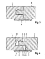
- zwei miteinander montierte Paneelelemente mit Nullfuge und einer Klammer, die nicht die Erfindung zeigt, und
- Fig. 4
- ein anderes Ausführungsbeispiel einer erfin- dungsgemäßen Klammer.
- In allen Figuren werden für gleiche bzw. gleichartige Bauteile übereinstimmende Bezugszeichen verwendet.
- In den Figuren sind Paneelelemente 1, 2 dargestellt, die mittels einer Klammer 3 auf einem Untergrund 4 befestigt sind. Bei dem Untergrund 4 kann es sich beispielsweise um eine Raumwand oder eine Raumdecke handeln. Die Befestigung der Klammer 3 auf dem Untergrund erfolgt beispielsweise mittels Schrauben, die als strichpunktierte Linie angedeutet sind.
- Die Paneelelemente 1, 2 weisen an einer Längs- und/oder Querkante eine Feder 5 mit einer oberen und einer unteren Federfläche auf, welche die betreffende Kante in einen oberen und einen unteren Kantenabschnitt 6, 7 mit einer oberen und einer unteren Nutflanke unterteilt. In dem dargestellten Ausführungsbeispiel ist auf der Oberseite der Feder 5 ein in etwa halbkreisförmig ausgebildeter Vorsprung 8 vorgesehen.
- An der gegenüberliegenden Längs- und/oder Querkante ist eine mit der Feder 5 korrespondierende Nut 9 vorgesehen, die die betreffende Kante in einen oberen und einen unteren Kantenabschnitt 6, 7 aufteilt. In dem oberen Kantenabschnitt 6 der Nut 9 sind in unterschiedlichem Abstand zur Stirnkante Ausnehmungen 10 vorgesehen, deren Querschnitt in etwa der Ausgestaltung des Vorsprungs 8 entspricht.
- Für die Befestigung der Paneelelemente 1, 2 ist die Klammer 3 vorgesehen, die eine auf dem Untergrund 4 zu befestigende Grundplatte 11 aufweist, an der ein Steg 12 mit einer endseitigen, zur Grundplatte 11 im Wesentlichen parallelen Abwinklung 13, vorgesehen ist. Zusätzlich ist an der Abwinklung 13 endseitig ein von der Grundplatte 11 wegweisender, in etwa rechtwinklig abgewinkelter Anlagesteg 14 vorgesehen.
- Bei der in den
Fig. 1 und 2 dargestellten Klammer 3 ist der Abstand zwischen dem Steg 12 und dem Anlagesteg 14, d.h. die Breite der Abwinklung 13, kleiner als die Tiefe der Nut 9. Dies hat zur Folge, dass im eingeführten Zustand der Steg 12 mit dem unteren Kantenabschnitt 7 des Paneelelementes 1 (Nutpaneel) in Kontakt ist, während die Federstirnfläche der Feder 3 des Paneelelementes 2 (Federpaneel) den Anlagesteg 14 berührt, so dass damit die Einführtiefe bestimmt wird. Damit ergibt sich vorderseitig eine Sichtfuge 15. - In
Fig. 4 ist die Klammer 3 hinsichtlich der Dimensionierung der Abwinklung 13 anders ausgestaltet. Hier ist der Abstand zwischen dem Steg 12 und dem Anlagesteg 14, d.h. die Breite der Abwinklung 13, größer als die Tiefe der Nut 9. Damit liegt der untere Kantenabschnitt 7 des Paneelelementes 2 (Federpaneel) an dem Steg 12 und der Anlagesteg 14 an dem Nutgrund des Paneelelementes 1 (Nutpaneel) an, so dass damit die Einführtiefe bestimmt wird. Damit ergibt sich auch hier vorderseitig die Sichtfuge 15. Es ist selbstverständlich, dass auf den Anlagesteg 14 verzichtet werden kann, so dass dann das freie Ende der Abwinklung 13 an dem Nutgrund anliegt. - Bei "Entfernen" des Anlagestegs 14, so wie es in
Fig. 3 dargestellt ist, kann eine Nullfuge im Bereich der Sichtseite zwischen zwei benachbarten Paneelelementen 1, 2 hergestellt werden, sofern die Länge der Abwinklung 13 kleiner als die Länge der unteren Nutflanke des unteren Kantenabschnitts 7 ist. Bei diesem Ausführungsbeispiel berühren der untere Kantenabschnitt 7 des Paneelelementes 2 (Federpaneel) und der untere Kantenabschnitt 7 des Paneelelementes 1 (Nutpaneel) den Steg 12. - Bei den dargestellten Ausführungsbeispielen findet sowohl bei Wahl einer frontseitigen Sichtfuge 15 als auch bei Wahl einer frontseitigen Nullfuge eine zusätzliche Verrastung durch das Zusammenwirken des Vorsprungs 8 und der Ausnehmung 10 statt. Durch Vergrößerung der Anzahl an Ausnehmungen 10 kann die Anzahl an einzustellenden Sichtfugenbreiten variiert werden, wobei hierauf die Klammer 3 abzustimmen ist.
- Selbstverständlich können mit der erfindungsgemäßen Klammer auch Paneelelemente 1,2 ohne Vorsprung 8 und Ausnehmung 10 befestigt werden.
Claims (5)
- System, mit wenigstens zwei Paneelelementen und wenigstens einer Klammer, wobei die Klammer (3) zur Befestigung von Paneelelementen (1, 2) an einem Untergrund (4) ausgebildet ist, wobei die Paneelelemente (1,2) an einer Längs- und/oder Querkante eine die betreffende Kante in einen oberen und einen unteren Kantenabschnitt (6, 7) aufteilende Feder (5) mit einer oberen Federflanke und einer unteren Federflanke, und an der gegenüberliegenden Längs- und/oder Querkante eine mit der Feder korrespondierende, die betreffende Kante in einen oberen und einen unteren Kantenabschnitt (6, 7) aufteilende Nut (9) mit einer oberen Nutflanke und einer unteren Nutflanke aufweisen, wobei die Klammer (3) eine auf dem Untergrund (4) zu befestigende Grundplatte (11) aufweist, an der ein Steg (12) mit einer endseitigen, zur Grundplatte (11) im Wesentlichen parallelen Abwinklung (13) vorgesehen ist, wobei im montierten Zustand zweier benachbarter Paneelelemente (1, 2) der Steg (12) zumindest in etwa an dem unteren Kantenabschnitt (7) eines Paneelelementes (1, 2) anliegt und die Abwinklung (13) zwischen der unterseitigen Federflanke der Feder (5) und den die untere Nutflanke der Nut (9) bildenden Teilbereich des unteren Kantenabschnitts (7) eingeführt ist, dadurch gekennzeichnet, dass zur Begrenzung der Einführtiefe der Feder (5) des Paneelelementes (2) in die Nut (9) des benachbarten Paneelelementes (1) die Länge der Abwinklung (13) größer ist als die Länge der unteren Nutflanke des unteren Kantenabschnitts (7), so dass der Nutgrund im eingeführten Zustand stirnseitig an dem freien Ende der Abwinklung (13) anliegt.
- System nach dem vorhergehenden Anspruch, dadurch gekennzeichnet, dass die Klammer (3) an der Abwinklung (13) endseitig mit einem von der Grundplatte (11) weg weisenden, in etwa rechtwinklig abgewinkelten Anlagesteg (14) versehen ist.
- System, mit wenigstens zwei Paneelelementen und wenigstens einer Klammer, wobei die Klammer (3) zur Befestigung von Paneelelementen (1, 2) an einem Untergrund (4) ausgebildet ist, wobei die Paneelelemente (1, 2) an einer Längs- und/oder Querkante eine die betreffende Kante in einen oberen und einen unteren Kantenabschnitt (6, 7) aufteilende Feder (5) mit einer oberen Federflanke und einer unteren Federflanke, und an der gegenüberliegenden Längs- und/oder Querkante eine mit der Feder korrespondierende, die betreffende Kante in einen oberen und einen unteren Kantenabschnitt (6, 7) aufteilende Nut (9) mit einer oberen Nutflanke und einer unteren Nutflanke aufweisen, wobei die Klammer (3) eine auf dem Untergrund (4) zu befestigende Grundplatte (11) aufweist, an der ein Steg (12) mit einer endseitigen, zur Grundplatte (11) im Wesentlichen parallelen Abwinklung (13) vorgesehen ist, und die Klammer (3) an der Abwinklung (13) endseitig mit einem von der Grundplatte (11) weg weisenden, in etwa rechtwinklig abgewinkelten Anlagesteg (14) versehen ist, wobei im montierten Zustand zweier benachbarter Paneelelemente (1, 2) der Steg (12) zumindest in etwa an dem unteren Kantenabschnitt (7) eines Paneelelementes (1, 2) anliegt und die Abwinklung (13) zwischen der unterseitigen Federflanke der Feder (5) und den die untere Nutflanke der Nut (9) bildenden Teilbereich des unteren Kantenabschnitts (7) eingeführt ist, dadurch gekennzeichnet, dass zur Begrenzung der Einführtiefe der Feder (5) des Paneelelementes (2) in die Nut (9) des benachbarten Paneelelements (1) Länge der Abwinklung (13) kleiner ist als die Länge der unteren Federflanke, so dass die Federstirnfläche im eingeführten Zustand stirnseitig an dem Anlagesteg(14) anliegt.
- System nach den Ansprüchen 2 und 3, dadurch gekennzeichnet, dass der Anlagesteg (14) eine geringere Höhe als die Nut (9) aufweist.
- System nach einem der vorhergehenden Ansprüche, dadurch gekennzeichnet, dass die Höhe des Steges (12) etwas größer als die Höhe des unteren Kantenabschnittes (7) ist.
Applications Claiming Priority (2)
| Application Number | Priority Date | Filing Date | Title |
|---|---|---|---|
| DE202006005470U DE202006005470U1 (de) | 2006-04-05 | 2006-04-05 | Klammer zur Befestigung von Paneelelementen |
| PCT/EP2007/003002 WO2007115747A1 (de) | 2006-04-05 | 2007-04-03 | Klammer zur befestigung von paneelelementen |
Publications (3)
| Publication Number | Publication Date |
|---|---|
| EP2002068A1 EP2002068A1 (de) | 2008-12-17 |
| EP2002068B1 EP2002068B1 (de) | 2010-07-21 |
| EP2002068B9 true EP2002068B9 (de) | 2010-12-22 |
Family
ID=36794631
Family Applications (1)
| Application Number | Title | Priority Date | Filing Date |
|---|---|---|---|
| EP07723943A Not-in-force EP2002068B9 (de) | 2006-04-05 | 2007-04-03 | Klammer zur befestigung von paneelelementen |
Country Status (4)
| Country | Link |
|---|---|
| EP (1) | EP2002068B9 (de) |
| AT (1) | ATE474977T1 (de) |
| DE (2) | DE202006005470U1 (de) |
| WO (1) | WO2007115747A1 (de) |
Families Citing this family (13)
| Publication number | Priority date | Publication date | Assignee | Title |
|---|---|---|---|---|
| BE1018480A3 (nl) * | 2008-04-16 | 2011-01-11 | Flooring Ind Ltd Sarl | Vloerpanelen, vloerbekleding daaruit samengesteld, en werkwijze voor het vervaardigen van dergelijke vloerpanelen. |
| IT1392124B1 (it) * | 2008-12-03 | 2012-02-22 | Lolli | Incastro a scorrimento longitudinale e metodo di produzione |
| EP2333353A3 (de) * | 2009-12-02 | 2012-07-25 | Lolli, Paride | Längsverschiebbare Verbindung |
| GB2477587A (en) * | 2010-07-28 | 2011-08-10 | Architectural Facades And Soffit Systems Ltd | Cladding panels made to resemble tiling |
| EP2664730A1 (de) | 2012-05-15 | 2013-11-20 | Falquon GmbH | Paneel für eine flächige Verlegung als Verkleidung oder Belag mit verbesserter Widerstandsfähigkeit gegenüber Feuchtigkeit |
| NL2010396C2 (en) * | 2013-03-05 | 2014-09-08 | Soederhuizen Stenen B V | Underlayment tile. |
| FR3009731A1 (fr) * | 2013-08-19 | 2015-02-20 | Findes | Lames de revetements assemblables bord a bord par emboitement autobloquant et accessoires de pose pour leur solidarisation avec une paroi |
| CN105804350A (zh) * | 2016-03-14 | 2016-07-27 | 金螳螂精装科技(苏州)有限公司 | 木饰面插槽式安装结构 |
| JP6662938B2 (ja) * | 2018-03-30 | 2020-03-11 | 株式会社ホンダアクセス | 取付構造及び取付方法 |
| CN110158854A (zh) * | 2019-05-29 | 2019-08-23 | 江苏工程职业技术学院 | 一种建筑防水保温隔热复合板及生产方法 |
| CN110439888A (zh) * | 2019-08-05 | 2019-11-12 | 深圳市金裕仁实业有限公司 | 一种采用公母凹凸扣件形式的连接件 |
| CN111734075A (zh) * | 2020-06-02 | 2020-10-02 | 广东优美仕新材料科技有限公司 | 一种陶瓷面锁扣地板及其安装工艺 |
| FR3162772A1 (fr) | 2024-05-30 | 2025-12-05 | Bernard Proot | Panneau de revêtement reversible et son procede de pose |
Family Cites Families (9)
| Publication number | Priority date | Publication date | Assignee | Title |
|---|---|---|---|---|
| US2317428A (en) * | 1940-01-12 | 1943-04-27 | Wood Conversion Co | Wall tile clip |
| CH670857A5 (de) * | 1987-01-30 | 1989-07-14 | Morandi Freres Sa | |
| FR2614340B1 (fr) * | 1987-04-23 | 1989-07-28 | Smac Acieroid | Dispositif de fixation des plaques d'un revetement de facade |
| US5634305A (en) * | 1992-05-18 | 1997-06-03 | Erlanger; Israel | System for stone cladding of buildings |
| US5768850A (en) * | 1997-02-04 | 1998-06-23 | Chen; Alen | Method for erecting floor boards and a board assembly using the method |
| DE19718716C2 (de) * | 1997-05-02 | 2002-08-01 | Max Gerhaher | Vorgehängte Fassadenkonstruktion |
| DE10041775C1 (de) * | 2000-08-25 | 2003-02-06 | Fauner Gerhard | Befestigungssystem für Wandelemente an Gebäudewänden |
| DE20202059U1 (de) * | 2002-02-12 | 2002-07-04 | Wendker Fassaden-Systembau GmbH, 45701 Herten | Befestigungssystem für kleinformatige Wandelemente an Gebäudewänden |
| WO2006032378A1 (de) * | 2004-09-17 | 2006-03-30 | Hdm Gmbh | Paneel, insbesondere fussbodenpaneel |
-
2006
- 2006-04-05 DE DE202006005470U patent/DE202006005470U1/de not_active Expired - Lifetime
-
2007
- 2007-04-03 EP EP07723943A patent/EP2002068B9/de not_active Not-in-force
- 2007-04-03 WO PCT/EP2007/003002 patent/WO2007115747A1/de not_active Ceased
- 2007-04-03 DE DE502007004484T patent/DE502007004484D1/de active Active
- 2007-04-03 AT AT07723943T patent/ATE474977T1/de active
Also Published As
| Publication number | Publication date |
|---|---|
| ATE474977T1 (de) | 2010-08-15 |
| EP2002068A1 (de) | 2008-12-17 |
| EP2002068B1 (de) | 2010-07-21 |
| WO2007115747A1 (de) | 2007-10-18 |
| DE202006005470U1 (de) | 2006-07-27 |
| DE502007004484D1 (de) | 2010-09-02 |
Similar Documents
| Publication | Publication Date | Title |
|---|---|---|
| EP2002068B1 (de) | Klammer zur befestigung von paneelelementen | |
| EP1965680B1 (de) | Schnellbefestigungselement | |
| EP2013493B1 (de) | Befestigungsvorrichtung | |
| DE10107864C2 (de) | Halteelement für Abdeckleisten | |
| DE102008009608A1 (de) | Einrichtung mit einem Flächenelement und einer Klemmeinrichtung | |
| WO2014005164A1 (de) | Schublade | |
| AT503228A1 (de) | Vorrichtung zur befestigung einer abschlussleiste | |
| WO2008077858A1 (de) | Halterung | |
| DE102015006108B4 (de) | Klemmverbindungsvorrichtung | |
| EP2775068B1 (de) | Hilfsvorrichtung zum Verlegen von Fliesen | |
| EP2840933B1 (de) | Schubladenrückwand | |
| DE102013105047B4 (de) | Anordnung zum Befestigen einer Schiene | |
| EP2530227B1 (de) | Flächenbündiges Scharnier für Glaselemente | |
| EP4126736B1 (de) | Positionierhilfe zum positionieren einer mutter an einer führungsschiene einer aufzugsanlage | |
| EP1901407A1 (de) | Hutschienenträger und Hutschiene mit zwei Hutschienenträgern | |
| DE102007051058B4 (de) | Befestigungsklammer und System zum Erstellen von Aufbauten | |
| DE102018005072A1 (de) | Befestigungselement zur Montage einer Fassadenpaneele | |
| EP1459938B1 (de) | Befestigungsvorrichtung zur lösbaren Festlegung eines Bauteils an einem Trägerteil | |
| EP1811233A1 (de) | Wandbefestigungssystem mit Abstandshalter für mit Aufhängelaschen versehene plattenförmige Gegenstände wie Heizkörper | |
| EP2065521B1 (de) | Befestigungssystem zur Befestigung eines Geräteeinsatzes in einer Einbauöffnung einer Arbeitsplatte. | |
| EP2309070B1 (de) | Bauelement für Decken- und Wandbogenplatten sowie Verfahren zu dessen Herstellung | |
| DE20114555U1 (de) | Ankerwinkel | |
| DE10156221C1 (de) | Vorrichtung zum Befestigen von Bauteilen | |
| EP0852836B1 (de) | Verbindungselement zum befestigen von tragelementen | |
| DE29805591U1 (de) | Verbindungselement |
Legal Events
| Date | Code | Title | Description |
|---|---|---|---|
| PUAI | Public reference made under article 153(3) epc to a published international application that has entered the european phase |
Free format text: ORIGINAL CODE: 0009012 |
|
| 17P | Request for examination filed |
Effective date: 20081002 |
|
| AK | Designated contracting states |
Kind code of ref document: A1 Designated state(s): AT BE BG CH CY CZ DE DK EE ES FI FR GB GR HU IE IS IT LI LT LU LV MC MT NL PL PT RO SE SI SK TR |
|
| GRAP | Despatch of communication of intention to grant a patent |
Free format text: ORIGINAL CODE: EPIDOSNIGR1 |
|
| DAX | Request for extension of the european patent (deleted) | ||
| GRAS | Grant fee paid |
Free format text: ORIGINAL CODE: EPIDOSNIGR3 |
|
| GRAA | (expected) grant |
Free format text: ORIGINAL CODE: 0009210 |
|
| AK | Designated contracting states |
Kind code of ref document: B1 Designated state(s): AT BE BG CH CY CZ DE DK EE ES FI FR GB GR HU IE IS IT LI LT LU LV MC MT NL PL PT RO SE SI SK TR |
|
| REG | Reference to a national code |
Ref country code: GB Ref legal event code: FG4D Free format text: NOT ENGLISH |
|
| REG | Reference to a national code |
Ref country code: CH Ref legal event code: EP |
|
| REG | Reference to a national code |
Ref country code: IE Ref legal event code: FG4D |
|
| REF | Corresponds to: |
Ref document number: 502007004484 Country of ref document: DE Date of ref document: 20100902 Kind code of ref document: P |
|
| REG | Reference to a national code |
Ref country code: NL Ref legal event code: VDEP Effective date: 20100721 |
|
| LTIE | Lt: invalidation of european patent or patent extension |
Effective date: 20100721 |
|
| PG25 | Lapsed in a contracting state [announced via postgrant information from national office to epo] |
Ref country code: LT Free format text: LAPSE BECAUSE OF FAILURE TO SUBMIT A TRANSLATION OF THE DESCRIPTION OR TO PAY THE FEE WITHIN THE PRESCRIBED TIME-LIMIT Effective date: 20100721 Ref country code: NL Free format text: LAPSE BECAUSE OF FAILURE TO SUBMIT A TRANSLATION OF THE DESCRIPTION OR TO PAY THE FEE WITHIN THE PRESCRIBED TIME-LIMIT Effective date: 20100721 Ref country code: FI Free format text: LAPSE BECAUSE OF FAILURE TO SUBMIT A TRANSLATION OF THE DESCRIPTION OR TO PAY THE FEE WITHIN THE PRESCRIBED TIME-LIMIT Effective date: 20100721 |
|
| REG | Reference to a national code |
Ref country code: IE Ref legal event code: FD4D |
|
| PG25 | Lapsed in a contracting state [announced via postgrant information from national office to epo] |
Ref country code: PT Free format text: LAPSE BECAUSE OF FAILURE TO SUBMIT A TRANSLATION OF THE DESCRIPTION OR TO PAY THE FEE WITHIN THE PRESCRIBED TIME-LIMIT Effective date: 20101122 Ref country code: IS Free format text: LAPSE BECAUSE OF FAILURE TO SUBMIT A TRANSLATION OF THE DESCRIPTION OR TO PAY THE FEE WITHIN THE PRESCRIBED TIME-LIMIT Effective date: 20101121 Ref country code: CY Free format text: LAPSE BECAUSE OF FAILURE TO SUBMIT A TRANSLATION OF THE DESCRIPTION OR TO PAY THE FEE WITHIN THE PRESCRIBED TIME-LIMIT Effective date: 20100721 Ref country code: BG Free format text: LAPSE BECAUSE OF FAILURE TO SUBMIT A TRANSLATION OF THE DESCRIPTION OR TO PAY THE FEE WITHIN THE PRESCRIBED TIME-LIMIT Effective date: 20101021 Ref country code: PL Free format text: LAPSE BECAUSE OF FAILURE TO SUBMIT A TRANSLATION OF THE DESCRIPTION OR TO PAY THE FEE WITHIN THE PRESCRIBED TIME-LIMIT Effective date: 20100721 Ref country code: SI Free format text: LAPSE BECAUSE OF FAILURE TO SUBMIT A TRANSLATION OF THE DESCRIPTION OR TO PAY THE FEE WITHIN THE PRESCRIBED TIME-LIMIT Effective date: 20100721 |
|
| PG25 | Lapsed in a contracting state [announced via postgrant information from national office to epo] |
Ref country code: SE Free format text: LAPSE BECAUSE OF FAILURE TO SUBMIT A TRANSLATION OF THE DESCRIPTION OR TO PAY THE FEE WITHIN THE PRESCRIBED TIME-LIMIT Effective date: 20100721 Ref country code: GR Free format text: LAPSE BECAUSE OF FAILURE TO SUBMIT A TRANSLATION OF THE DESCRIPTION OR TO PAY THE FEE WITHIN THE PRESCRIBED TIME-LIMIT Effective date: 20101022 Ref country code: LV Free format text: LAPSE BECAUSE OF FAILURE TO SUBMIT A TRANSLATION OF THE DESCRIPTION OR TO PAY THE FEE WITHIN THE PRESCRIBED TIME-LIMIT Effective date: 20100721 |
|
| PG25 | Lapsed in a contracting state [announced via postgrant information from national office to epo] |
Ref country code: DK Free format text: LAPSE BECAUSE OF FAILURE TO SUBMIT A TRANSLATION OF THE DESCRIPTION OR TO PAY THE FEE WITHIN THE PRESCRIBED TIME-LIMIT Effective date: 20100721 Ref country code: IE Free format text: LAPSE BECAUSE OF FAILURE TO SUBMIT A TRANSLATION OF THE DESCRIPTION OR TO PAY THE FEE WITHIN THE PRESCRIBED TIME-LIMIT Effective date: 20100721 |
|
| PLBE | No opposition filed within time limit |
Free format text: ORIGINAL CODE: 0009261 |
|
| STAA | Information on the status of an ep patent application or granted ep patent |
Free format text: STATUS: NO OPPOSITION FILED WITHIN TIME LIMIT |
|
| PG25 | Lapsed in a contracting state [announced via postgrant information from national office to epo] |
Ref country code: EE Free format text: LAPSE BECAUSE OF FAILURE TO SUBMIT A TRANSLATION OF THE DESCRIPTION OR TO PAY THE FEE WITHIN THE PRESCRIBED TIME-LIMIT Effective date: 20100721 Ref country code: IT Free format text: LAPSE BECAUSE OF FAILURE TO SUBMIT A TRANSLATION OF THE DESCRIPTION OR TO PAY THE FEE WITHIN THE PRESCRIBED TIME-LIMIT Effective date: 20100721 Ref country code: SK Free format text: LAPSE BECAUSE OF FAILURE TO SUBMIT A TRANSLATION OF THE DESCRIPTION OR TO PAY THE FEE WITHIN THE PRESCRIBED TIME-LIMIT Effective date: 20100721 Ref country code: RO Free format text: LAPSE BECAUSE OF FAILURE TO SUBMIT A TRANSLATION OF THE DESCRIPTION OR TO PAY THE FEE WITHIN THE PRESCRIBED TIME-LIMIT Effective date: 20100721 Ref country code: CZ Free format text: LAPSE BECAUSE OF FAILURE TO SUBMIT A TRANSLATION OF THE DESCRIPTION OR TO PAY THE FEE WITHIN THE PRESCRIBED TIME-LIMIT Effective date: 20100721 |
|
| 26N | No opposition filed |
Effective date: 20110426 |
|
| PG25 | Lapsed in a contracting state [announced via postgrant information from national office to epo] |
Ref country code: ES Free format text: LAPSE BECAUSE OF FAILURE TO SUBMIT A TRANSLATION OF THE DESCRIPTION OR TO PAY THE FEE WITHIN THE PRESCRIBED TIME-LIMIT Effective date: 20101101 |
|
| PGFP | Annual fee paid to national office [announced via postgrant information from national office to epo] |
Ref country code: FR Payment date: 20110630 Year of fee payment: 5 |
|
| REG | Reference to a national code |
Ref country code: DE Ref legal event code: R097 Ref document number: 502007004484 Country of ref document: DE Effective date: 20110426 |
|
| BERE | Be: lapsed |
Owner name: HDM G.M.B.H. Effective date: 20110430 |
|
| PG25 | Lapsed in a contracting state [announced via postgrant information from national office to epo] |
Ref country code: MC Free format text: LAPSE BECAUSE OF NON-PAYMENT OF DUE FEES Effective date: 20110430 |
|
| PGFP | Annual fee paid to national office [announced via postgrant information from national office to epo] |
Ref country code: DE Payment date: 20110620 Year of fee payment: 5 |
|
| REG | Reference to a national code |
Ref country code: CH Ref legal event code: PL |
|
| GBPC | Gb: european patent ceased through non-payment of renewal fee |
Effective date: 20110403 |
|
| PG25 | Lapsed in a contracting state [announced via postgrant information from national office to epo] |
Ref country code: MT Free format text: LAPSE BECAUSE OF FAILURE TO SUBMIT A TRANSLATION OF THE DESCRIPTION OR TO PAY THE FEE WITHIN THE PRESCRIBED TIME-LIMIT Effective date: 20100721 |
|
| PG25 | Lapsed in a contracting state [announced via postgrant information from national office to epo] |
Ref country code: CH Free format text: LAPSE BECAUSE OF NON-PAYMENT OF DUE FEES Effective date: 20110430 Ref country code: LI Free format text: LAPSE BECAUSE OF NON-PAYMENT OF DUE FEES Effective date: 20110430 Ref country code: BE Free format text: LAPSE BECAUSE OF NON-PAYMENT OF DUE FEES Effective date: 20110430 |
|
| PG25 | Lapsed in a contracting state [announced via postgrant information from national office to epo] |
Ref country code: GB Free format text: LAPSE BECAUSE OF NON-PAYMENT OF DUE FEES Effective date: 20110403 |
|
| REG | Reference to a national code |
Ref country code: FR Ref legal event code: ST Effective date: 20121228 |
|
| REG | Reference to a national code |
Ref country code: DE Ref legal event code: R119 Ref document number: 502007004484 Country of ref document: DE Effective date: 20121101 |
|
| PG25 | Lapsed in a contracting state [announced via postgrant information from national office to epo] |
Ref country code: FR Free format text: LAPSE BECAUSE OF NON-PAYMENT OF DUE FEES Effective date: 20120430 |
|
| PG25 | Lapsed in a contracting state [announced via postgrant information from national office to epo] |
Ref country code: LU Free format text: LAPSE BECAUSE OF NON-PAYMENT OF DUE FEES Effective date: 20110403 |
|
| REG | Reference to a national code |
Ref country code: AT Ref legal event code: MM01 Ref document number: 474977 Country of ref document: AT Kind code of ref document: T Effective date: 20120403 |
|
| PG25 | Lapsed in a contracting state [announced via postgrant information from national office to epo] |
Ref country code: AT Free format text: LAPSE BECAUSE OF NON-PAYMENT OF DUE FEES Effective date: 20120403 |
|
| PG25 | Lapsed in a contracting state [announced via postgrant information from national office to epo] |
Ref country code: TR Free format text: LAPSE BECAUSE OF FAILURE TO SUBMIT A TRANSLATION OF THE DESCRIPTION OR TO PAY THE FEE WITHIN THE PRESCRIBED TIME-LIMIT Effective date: 20100721 |
|
| PG25 | Lapsed in a contracting state [announced via postgrant information from national office to epo] |
Ref country code: HU Free format text: LAPSE BECAUSE OF FAILURE TO SUBMIT A TRANSLATION OF THE DESCRIPTION OR TO PAY THE FEE WITHIN THE PRESCRIBED TIME-LIMIT Effective date: 20100721 |
|
| PG25 | Lapsed in a contracting state [announced via postgrant information from national office to epo] |
Ref country code: DE Free format text: LAPSE BECAUSE OF NON-PAYMENT OF DUE FEES Effective date: 20121101 |