EP2002068B9 - Pince pour la fixation d'elements en panneau - Google Patents
Pince pour la fixation d'elements en panneau Download PDFInfo
- Publication number
- EP2002068B9 EP2002068B9 EP07723943A EP07723943A EP2002068B9 EP 2002068 B9 EP2002068 B9 EP 2002068B9 EP 07723943 A EP07723943 A EP 07723943A EP 07723943 A EP07723943 A EP 07723943A EP 2002068 B9 EP2002068 B9 EP 2002068B9
- Authority
- EP
- European Patent Office
- Prior art keywords
- spring
- groove
- flank
- web
- clip
- Prior art date
- Legal status (The legal status is an assumption and is not a legal conclusion. Google has not performed a legal analysis and makes no representation as to the accuracy of the status listed.)
- Not-in-force
Links
- 230000037431 insertion Effects 0.000 claims abstract description 9
- 238000003780 insertion Methods 0.000 claims abstract description 9
- 239000000758 substrate Substances 0.000 description 3
- 239000000463 material Substances 0.000 description 2
- 230000003247 decreasing effect Effects 0.000 description 1
- 230000003993 interaction Effects 0.000 description 1
- 239000002184 metal Substances 0.000 description 1
- 230000000007 visual effect Effects 0.000 description 1
Images

Classifications
-
- F—MECHANICAL ENGINEERING; LIGHTING; HEATING; WEAPONS; BLASTING
- F16—ENGINEERING ELEMENTS AND UNITS; GENERAL MEASURES FOR PRODUCING AND MAINTAINING EFFECTIVE FUNCTIONING OF MACHINES OR INSTALLATIONS; THERMAL INSULATION IN GENERAL
- F16B—DEVICES FOR FASTENING OR SECURING CONSTRUCTIONAL ELEMENTS OR MACHINE PARTS TOGETHER, e.g. NAILS, BOLTS, CIRCLIPS, CLAMPS, CLIPS OR WEDGES; JOINTS OR JOINTING
- F16B5/00—Joining sheets or plates, e.g. panels, to one another or to strips or bars parallel to them
- F16B5/0004—Joining sheets, plates or panels in abutting relationship
- F16B5/0008—Joining sheets, plates or panels in abutting relationship by moving the sheets, plates or panels substantially in their own plane, perpendicular to the abutting edge
- F16B5/0012—Joining sheets, plates or panels in abutting relationship by moving the sheets, plates or panels substantially in their own plane, perpendicular to the abutting edge a tongue on the edge of one sheet, plate or panel co-operating with a groove in the edge of another sheet, plate or panel
-
- E—FIXED CONSTRUCTIONS
- E04—BUILDING
- E04F—FINISHING WORK ON BUILDINGS, e.g. STAIRS, FLOORS
- E04F13/00—Coverings or linings, e.g. for walls or ceilings
- E04F13/07—Coverings or linings, e.g. for walls or ceilings composed of covering or lining elements; Sub-structures therefor; Fastening means therefor
- E04F13/08—Coverings or linings, e.g. for walls or ceilings composed of covering or lining elements; Sub-structures therefor; Fastening means therefor composed of a plurality of similar covering or lining elements
-
- E—FIXED CONSTRUCTIONS
- E04—BUILDING
- E04F—FINISHING WORK ON BUILDINGS, e.g. STAIRS, FLOORS
- E04F2201/00—Joining sheets or plates or panels
- E04F2201/01—Joining sheets, plates or panels with edges in abutting relationship
- E04F2201/0107—Joining sheets, plates or panels with edges in abutting relationship by moving the sheets, plates or panels substantially in their own plane, perpendicular to the abutting edges
- E04F2201/0115—Joining sheets, plates or panels with edges in abutting relationship by moving the sheets, plates or panels substantially in their own plane, perpendicular to the abutting edges with snap action of the edge connectors
-
- E—FIXED CONSTRUCTIONS
- E04—BUILDING
- E04F—FINISHING WORK ON BUILDINGS, e.g. STAIRS, FLOORS
- E04F2201/00—Joining sheets or plates or panels
- E04F2201/05—Separate connectors or inserts, e.g. pegs, pins, keys or strips
Definitions
- the invention relates to a system comprising at least two panel elements and at least one clip, wherein the clip is adapted for mounting Päneelelementen on a substrate, wherein the panel elements at a longitudinal and / or transverse edge of a respective edge in an upper and a lower edge portion dividing spring having an upper tongue edge and a lower tongue edge, and at the opposite longitudinal and / or transverse edge corresponding to the spring, the respective edge in an upper and a lower edge portion dividing groove having an upper groove flank and a lower groove flank, wherein the bracket has a base plate to be fastened to the base, on which a web is provided with an end, substantially parallel to the base plate angled, wherein in the assembled state of two adjacent panel elements of the web at least approximately abuts the lower edge portion of a panel element u nd the bend between the underside spring edge of the spring and the lower groove edge of the groove forming portion of the lower edge portion is introduced.
- Such panel elements are used for example for covering walls or rooms.
- the spring of the panel element to be fastened is inserted into the groove of the last panel element mounted on the base.
- the spring is completely inserted into the groove so that the two front edge portions of both panel elements touch each other for a good grip.
- the last mounted board is secured to the longitudinal edge with the groove with clamps.
- the clip is introduced with the bend in the groove and the base plate by suitable means, such as screws, attached to the ground.
- Systems of panel elements and brackets are from the DE 202 02 059 U1 , of the DE 100 41 7756 C1 , of the WO 2006/032378 A1 , of the U.S. Patent 5,768,850 , of the EP 0 875 642 A2 , of the U.S. Patent 2,317,428 and the CH 670-857 A5 known.
- the object of the invention is therefore to avoid the aforementioned disadvantages and to provide a system that also allow attachment of two adjacent panel elements at a distance to achieve a front view joint.
- the length of the bend larger is as the length of the lower groove edge of the lower edge portion, so that the groove base in the inserted state abuts the front end at the free end of the bend.
- the web abuts against the lower edge portion of the spring panel, while the free
- the length of the bend is greater than the depth of the groove. As the length of the bend becomes greater, the insertion depth is reduced more and more, so that the desired front-side visible joint is thereby increased.
- the clip can be provided at the angled end with a pointing away from the base plate, approximately at right angles angled investment web. As a result, the contact surface is increased to the groove bottom.
- the clamp is provided on the angled side end with a pointing away from the base plate, approximately at right angles angled investment web, the length of the angled smaller is as the length of the lower spring edge, so that the spring end face in the inserted state abuts the end face of the plant web.
- the lower edge portion of the Nutpaneels abuts the web and the spring end face of the adjacent spring panel on the abutment web.
- the length of the bend i. the distance between the web and contact bar, is less than the depth of the groove, with decreasing distance between the web and contact bar, the insertion depth is more and more reduced.
- the clip may be formed, for example, as a one-piece molded sheet metal part.
- the web is aligned approximately orthogonal to the longitudinal extent of the base plate. there is the material thickness, in particular of the web, as low as possible.
- the web has a slightly greater material thickness
- it is also suitable for the realization of a front-side zero joint, for example, if the edge of the lower edge portion is closer to the groove bottom than the edge of the upper edge portion.
- the lower edge portion of the spring panel can be arranged offset from the upper edge portion.
- the contact web may have a lower height than the groove.
- the height of the contact bar is chosen so that it does not exceed the height of the groove, so that the bend with the contact bar can be inserted into the groove.
- the height of the bridge can be slightly larger than the height of the lower edge section. In this embodiment, a secure hold of the fixed by means of the clip according to the invention panel elements is ensured in a direction perpendicular to the ground.
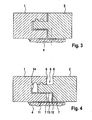
- panel elements 1, 2 are shown, which are fastened by means of a clamp 3 on a substrate 4.
- the substrate 4 may be, for example, a room wall or a room ceiling.
- the attachment of the bracket 3 on the ground for example, by means of screws, which are indicated as a dotted line.
- the panel elements 1, 2 have at a longitudinal and / or transverse edge on a spring 5 with an upper and a lower spring surface, which divides the relevant edge into an upper and a lower edge portion 6, 7 with an upper and a lower groove flank.
- an approximately semicircular formed projection 8 is provided on the upper side of the spring 5.
- a groove 9 corresponding to the tongue 5 is provided, which divides the relevant edge into an upper and a lower edge section 6, 7.
- recesses 10 are provided at different distances from the front edge, whose cross section corresponds approximately to the configuration of the projection 8.
- the bracket 3 which has a base plate 11 to be fastened to the base plate 11, on which a web 12 with an end, to the base plate 11 substantially parallel bend 13, is provided.
- a web 12 with an end to the base plate 11 substantially parallel bend 13
- the bracket 3 is provided, which has a base plate 11 to be fastened to the base plate 11, on which a web 12 with an end, to the base plate 11 substantially parallel bend 13, is provided.
- the bracket 3 is designed differently with regard to the dimensioning of the bend 13.
- the lower edge portion 7 of the panel element 2 (spring panel) on the web 12 and the contact web 14 at the Slot bottom of the panel element 1 (groove panel) so that so that the insertion depth is determined. It is obvious that can be dispensed with the system web 14, so that then the free end of the bend 13 abuts against the groove bottom.
- an additional latching takes place by the interaction of the projection 8 and the recess 10 both when selecting a front-side view joint 15 and when selecting a front-side zero joint.
Landscapes
- Engineering & Computer Science (AREA)
- General Engineering & Computer Science (AREA)
- Architecture (AREA)
- Mechanical Engineering (AREA)
- Civil Engineering (AREA)
- Structural Engineering (AREA)
- Connection Of Plates (AREA)
- Clamps And Clips (AREA)
Claims (5)
- Système comprenant au moins deux éléments de panneaux et au moins une bride, ladite bride (3) étant réalisée en vue de la fixation d'éléments de panneaux (1, 2) à une structure sous-jacente (4), lesdits éléments de panneaux (1, 2) comportant, sur un bord longitudinal et/ou transversal, une languette (5) qui présente un flanc supérieur et un flanc inférieur, et scinde le bord considéré en des régions marginales (6, 7) supérieure et inférieure, et comportant, sur le bord longitudinal et/ou transversal disposé en vis-à-vis, une rainure (9) qui offre un flanc supérieur et un flanc inférieur, concorde avec ladite languette et subdivise le bord considéré en des régions marginales (6, 7) supérieure et inférieure ; sachant que ladite bride (3) est munie d'une plaquette de base (11) conçue pour être fixée à la structure sous-jacente (4), et sur laquelle est prévue une membrure (12) dotée d'un coude extrême (13) substantiellement parallèle à ladite plaquette de base (11) ; et sachant que, à l'état monté de deux éléments de panneaux (1, 2) voisins, ladite membrure (12) est au moins sensiblement en applique contre la région marginale inférieure (7) d'un élément de panneau (1, 2), et ledit coude (13) est engagé entre le flanc situé à la face inférieure de ladite languette (5) et la zone partielle de la région marginale inférieure (7) qui matérialise le flanc inférieur de ladite rainure (9), caractérisé par le fait que, en vue de limiter la profondeur de pénétration de la languette (5) de l'élément de panneau (2) dans la rainure (9) de l'élément de panneau (1) voisin, la longueur du coude (13) est plus grande que la longueur du flanc inférieur de la rainure de la région marginale inférieure (7), de telle sorte que le fond de ladite rainure porte frontalement, à l'état inséré, contre l'extrémité libre dudit coude (13).
- Système selon la revendication précédente, caractérisé par le fait que la bride (3) est pourvue, à l'extrémité du coude (13), d'une nervure de contact (14) tournée à l'opposé de la plaquette de base (11) et sensiblement coudée à angle droit.
- Système comprenant au moins deux éléments de panneaux et au moins une bride, ladite bride (3) étant réalisée en vue de la fixation d'éléments de panneaux (1, 2) à une structure sous-jacente (4), lesdits éléments de panneaux (1, 2) comportant, sur un bord longitudinal et/ou transversal, une languette (5) qui présente un flanc supérieur et un flanc inférieur, et scinde le bord considéré en des régions marginales (6, 7) supérieure et inférieure, et comportant, sur le bord longitudinal et/ou transversal disposé en vis-à-vis, une rainure (9) qui offre un flanc supérieur et un flanc inférieur, concorde avec ladite languette et subdivise le bord considéré en des régions marginales (6, 7) supérieure et inférieure ; sachant que ladite bride (3) est munie d'une plaquette de base (11) conçue pour être fixée à la structure sous-jacente (4), et sur laquelle est prévue une membrure (12) dotée d'un coude extrême (13) substantiellement parallèle à ladite plaquette de base (11) ; sachant que ladite bride (3) est pourvue, à l'extrémité dudit coude (13), d'une nervure de contact (14) tournée à l'opposé de ladite plaquette de base (11) et sensiblement coudée à angle droit ; et sachant que, à l'état monté de deux éléments de panneaux (1, 2) voisins, ladite membrure (12) est au moins sensiblement en applique contre la région marginale inférieure (7) d'un élément de panneau (1, 2), et ledit coude (13) est engagé entre le flanc situé à la face inférieure de ladite languette (5) et la zone partielle de la région marginale inférieure (7) qui matérialise le flanc inférieur de ladite rainure (9), caractérisé par le fait que, en vue de limiter la profondeur de pénétration de la languette (5) de l'élément de panneau (2) dans la rainure (9) de l'élément de panneau (1) voisin, la longueur du coude (13) est plus petite que la longueur du flanc inférieur de ladite languette, de telle sorte que la face extrême de ladite languette porte frontalement, à l'état inséré, contre ladite nervure de contact (14).
- Système selon les revendications 2 et 3, caractérisé par le fait que la nervure de contact (14) présente une hauteur moindre que celle de la rainure (9).
- Système selon l'une des revendications précédentes, caractérisé par le fait que la hauteur de la membrure (12) est sensiblement plus grande que la hauteur de la région marginale inférieure (7).
Applications Claiming Priority (2)
| Application Number | Priority Date | Filing Date | Title |
|---|---|---|---|
| DE202006005470U DE202006005470U1 (de) | 2006-04-05 | 2006-04-05 | Klammer zur Befestigung von Paneelelementen |
| PCT/EP2007/003002 WO2007115747A1 (fr) | 2006-04-05 | 2007-04-03 | Pince pour la fixation d'elements en panneau |
Publications (3)
| Publication Number | Publication Date |
|---|---|
| EP2002068A1 EP2002068A1 (fr) | 2008-12-17 |
| EP2002068B1 EP2002068B1 (fr) | 2010-07-21 |
| EP2002068B9 true EP2002068B9 (fr) | 2010-12-22 |
Family
ID=36794631
Family Applications (1)
| Application Number | Title | Priority Date | Filing Date |
|---|---|---|---|
| EP07723943A Not-in-force EP2002068B9 (fr) | 2006-04-05 | 2007-04-03 | Pince pour la fixation d'elements en panneau |
Country Status (4)
| Country | Link |
|---|---|
| EP (1) | EP2002068B9 (fr) |
| AT (1) | ATE474977T1 (fr) |
| DE (2) | DE202006005470U1 (fr) |
| WO (1) | WO2007115747A1 (fr) |
Families Citing this family (13)
| Publication number | Priority date | Publication date | Assignee | Title |
|---|---|---|---|---|
| BE1018480A3 (nl) * | 2008-04-16 | 2011-01-11 | Flooring Ind Ltd Sarl | Vloerpanelen, vloerbekleding daaruit samengesteld, en werkwijze voor het vervaardigen van dergelijke vloerpanelen. |
| IT1392124B1 (it) * | 2008-12-03 | 2012-02-22 | Lolli | Incastro a scorrimento longitudinale e metodo di produzione |
| EP2333353A3 (fr) * | 2009-12-02 | 2012-07-25 | Lolli, Paride | Joint glissant dans la direction longitudinale |
| GB2477587A (en) * | 2010-07-28 | 2011-08-10 | Architectural Facades And Soffit Systems Ltd | Cladding panels made to resemble tiling |
| EP2664730A1 (fr) | 2012-05-15 | 2013-11-20 | Falquon GmbH | Panneau pour une pose à plat comme habillage ou revêtement avec une capacité de résistance améliorée contre l'humidité |
| NL2010396C2 (en) * | 2013-03-05 | 2014-09-08 | Soederhuizen Stenen B V | Underlayment tile. |
| FR3009731A1 (fr) * | 2013-08-19 | 2015-02-20 | Findes | Lames de revetements assemblables bord a bord par emboitement autobloquant et accessoires de pose pour leur solidarisation avec une paroi |
| CN105804350A (zh) * | 2016-03-14 | 2016-07-27 | 金螳螂精装科技(苏州)有限公司 | 木饰面插槽式安装结构 |
| JP6662938B2 (ja) * | 2018-03-30 | 2020-03-11 | 株式会社ホンダアクセス | 取付構造及び取付方法 |
| CN110158854A (zh) * | 2019-05-29 | 2019-08-23 | 江苏工程职业技术学院 | 一种建筑防水保温隔热复合板及生产方法 |
| CN110439888A (zh) * | 2019-08-05 | 2019-11-12 | 深圳市金裕仁实业有限公司 | 一种采用公母凹凸扣件形式的连接件 |
| CN111734075A (zh) * | 2020-06-02 | 2020-10-02 | 广东优美仕新材料科技有限公司 | 一种陶瓷面锁扣地板及其安装工艺 |
| FR3162772A1 (fr) | 2024-05-30 | 2025-12-05 | Bernard Proot | Panneau de revêtement reversible et son procede de pose |
Family Cites Families (9)
| Publication number | Priority date | Publication date | Assignee | Title |
|---|---|---|---|---|
| US2317428A (en) * | 1940-01-12 | 1943-04-27 | Wood Conversion Co | Wall tile clip |
| CH670857A5 (fr) * | 1987-01-30 | 1989-07-14 | Morandi Freres Sa | |
| FR2614340B1 (fr) * | 1987-04-23 | 1989-07-28 | Smac Acieroid | Dispositif de fixation des plaques d'un revetement de facade |
| AU4081093A (en) * | 1992-05-18 | 1993-12-13 | Israel Erlanger | A system for stone cladding of buildings |
| US5768850A (en) * | 1997-02-04 | 1998-06-23 | Chen; Alen | Method for erecting floor boards and a board assembly using the method |
| DE19718716C2 (de) * | 1997-05-02 | 2002-08-01 | Max Gerhaher | Vorgehängte Fassadenkonstruktion |
| DE10041775C1 (de) * | 2000-08-25 | 2003-02-06 | Fauner Gerhard | Befestigungssystem für Wandelemente an Gebäudewänden |
| DE20202059U1 (de) * | 2002-02-12 | 2002-07-04 | Wendker Fassaden-Systembau GmbH, 45701 Herten | Befestigungssystem für kleinformatige Wandelemente an Gebäudewänden |
| US7861483B2 (en) * | 2004-09-17 | 2011-01-04 | Dirk Dammers | Floor panel with the tongue more elastic than the locking element |
-
2006
- 2006-04-05 DE DE202006005470U patent/DE202006005470U1/de not_active Expired - Lifetime
-
2007
- 2007-04-03 EP EP07723943A patent/EP2002068B9/fr not_active Not-in-force
- 2007-04-03 WO PCT/EP2007/003002 patent/WO2007115747A1/fr not_active Ceased
- 2007-04-03 DE DE502007004484T patent/DE502007004484D1/de active Active
- 2007-04-03 AT AT07723943T patent/ATE474977T1/de active
Also Published As
| Publication number | Publication date |
|---|---|
| EP2002068B1 (fr) | 2010-07-21 |
| DE202006005470U1 (de) | 2006-07-27 |
| EP2002068A1 (fr) | 2008-12-17 |
| DE502007004484D1 (de) | 2010-09-02 |
| WO2007115747A1 (fr) | 2007-10-18 |
| ATE474977T1 (de) | 2010-08-15 |
Similar Documents
| Publication | Publication Date | Title |
|---|---|---|
| EP2002068B9 (fr) | Pince pour la fixation d'elements en panneau | |
| EP1965680B1 (fr) | Element de fixation rapide | |
| DE10107864C2 (de) | Halteelement für Abdeckleisten | |
| DE102008009608A1 (de) | Einrichtung mit einem Flächenelement und einer Klemmeinrichtung | |
| EP2866612A1 (fr) | Tiroir | |
| AT503228B1 (de) | Vorrichtung zur befestigung einer abschlussleiste | |
| EP2469182A2 (fr) | Système de rails télescopiques pour un appareil ménager | |
| WO2008077858A1 (fr) | Support | |
| DE102015006108B4 (de) | Klemmverbindungsvorrichtung | |
| EP2775068B1 (fr) | Dispositif auxiliaire pour la pose de carreaux | |
| EP2840933B1 (fr) | Panneau arrière d'un tiroir | |
| EP2530227B1 (fr) | Charnière à fixations affleurantes pour éléments de vitrerie | |
| EP4126736B1 (fr) | Aide au positionnement permettant de positionner un écrou sur un rail de guidage d'une installation d'ascenseur | |
| DE102013105047B4 (de) | Anordnung zum Befestigen einer Schiene | |
| EP1901407A1 (fr) | Support de profilé chapeau et profilé chapeau doté de deux supports de profilé chapeau | |
| DE102007051058B4 (de) | Befestigungsklammer und System zum Erstellen von Aufbauten | |
| DE102006055850A1 (de) | Untersparren-Dämmsystem für ein Steildach | |
| EP1459938B1 (fr) | Dispositif destiné à la fixation détachable d'un élément sur une partie support | |
| EP1811233A1 (fr) | Système de fixation au mur doté dýune entretoise pour des objets en forme de panneaux pourvus dýattaches de suspension comme des radiateurs de chauffage | |
| EP2065521B1 (fr) | Dispositif de fixation pour monter un apparail dans un trou de montage dans une plaque de support | |
| EP0609973A1 (fr) | Dispostif pour fixation des supports de couverture en angle | |
| DE10156221C1 (de) | Vorrichtung zum Befestigen von Bauteilen | |
| EP0852836B1 (fr) | Element de liaison pour la fixation d'elements porteurs | |
| DE29805591U1 (de) | Verbindungselement | |
| DE102005018048B4 (de) | Einbauleiste |
Legal Events
| Date | Code | Title | Description |
|---|---|---|---|
| PUAI | Public reference made under article 153(3) epc to a published international application that has entered the european phase |
Free format text: ORIGINAL CODE: 0009012 |
|
| 17P | Request for examination filed |
Effective date: 20081002 |
|
| AK | Designated contracting states |
Kind code of ref document: A1 Designated state(s): AT BE BG CH CY CZ DE DK EE ES FI FR GB GR HU IE IS IT LI LT LU LV MC MT NL PL PT RO SE SI SK TR |
|
| GRAP | Despatch of communication of intention to grant a patent |
Free format text: ORIGINAL CODE: EPIDOSNIGR1 |
|
| DAX | Request for extension of the european patent (deleted) | ||
| GRAS | Grant fee paid |
Free format text: ORIGINAL CODE: EPIDOSNIGR3 |
|
| GRAA | (expected) grant |
Free format text: ORIGINAL CODE: 0009210 |
|
| AK | Designated contracting states |
Kind code of ref document: B1 Designated state(s): AT BE BG CH CY CZ DE DK EE ES FI FR GB GR HU IE IS IT LI LT LU LV MC MT NL PL PT RO SE SI SK TR |
|
| REG | Reference to a national code |
Ref country code: GB Ref legal event code: FG4D Free format text: NOT ENGLISH |
|
| REG | Reference to a national code |
Ref country code: CH Ref legal event code: EP |
|
| REG | Reference to a national code |
Ref country code: IE Ref legal event code: FG4D |
|
| REF | Corresponds to: |
Ref document number: 502007004484 Country of ref document: DE Date of ref document: 20100902 Kind code of ref document: P |
|
| REG | Reference to a national code |
Ref country code: NL Ref legal event code: VDEP Effective date: 20100721 |
|
| LTIE | Lt: invalidation of european patent or patent extension |
Effective date: 20100721 |
|
| PG25 | Lapsed in a contracting state [announced via postgrant information from national office to epo] |
Ref country code: LT Free format text: LAPSE BECAUSE OF FAILURE TO SUBMIT A TRANSLATION OF THE DESCRIPTION OR TO PAY THE FEE WITHIN THE PRESCRIBED TIME-LIMIT Effective date: 20100721 Ref country code: NL Free format text: LAPSE BECAUSE OF FAILURE TO SUBMIT A TRANSLATION OF THE DESCRIPTION OR TO PAY THE FEE WITHIN THE PRESCRIBED TIME-LIMIT Effective date: 20100721 Ref country code: FI Free format text: LAPSE BECAUSE OF FAILURE TO SUBMIT A TRANSLATION OF THE DESCRIPTION OR TO PAY THE FEE WITHIN THE PRESCRIBED TIME-LIMIT Effective date: 20100721 |
|
| REG | Reference to a national code |
Ref country code: IE Ref legal event code: FD4D |
|
| PG25 | Lapsed in a contracting state [announced via postgrant information from national office to epo] |
Ref country code: PT Free format text: LAPSE BECAUSE OF FAILURE TO SUBMIT A TRANSLATION OF THE DESCRIPTION OR TO PAY THE FEE WITHIN THE PRESCRIBED TIME-LIMIT Effective date: 20101122 Ref country code: IS Free format text: LAPSE BECAUSE OF FAILURE TO SUBMIT A TRANSLATION OF THE DESCRIPTION OR TO PAY THE FEE WITHIN THE PRESCRIBED TIME-LIMIT Effective date: 20101121 Ref country code: CY Free format text: LAPSE BECAUSE OF FAILURE TO SUBMIT A TRANSLATION OF THE DESCRIPTION OR TO PAY THE FEE WITHIN THE PRESCRIBED TIME-LIMIT Effective date: 20100721 Ref country code: BG Free format text: LAPSE BECAUSE OF FAILURE TO SUBMIT A TRANSLATION OF THE DESCRIPTION OR TO PAY THE FEE WITHIN THE PRESCRIBED TIME-LIMIT Effective date: 20101021 Ref country code: PL Free format text: LAPSE BECAUSE OF FAILURE TO SUBMIT A TRANSLATION OF THE DESCRIPTION OR TO PAY THE FEE WITHIN THE PRESCRIBED TIME-LIMIT Effective date: 20100721 Ref country code: SI Free format text: LAPSE BECAUSE OF FAILURE TO SUBMIT A TRANSLATION OF THE DESCRIPTION OR TO PAY THE FEE WITHIN THE PRESCRIBED TIME-LIMIT Effective date: 20100721 |
|
| PG25 | Lapsed in a contracting state [announced via postgrant information from national office to epo] |
Ref country code: SE Free format text: LAPSE BECAUSE OF FAILURE TO SUBMIT A TRANSLATION OF THE DESCRIPTION OR TO PAY THE FEE WITHIN THE PRESCRIBED TIME-LIMIT Effective date: 20100721 Ref country code: GR Free format text: LAPSE BECAUSE OF FAILURE TO SUBMIT A TRANSLATION OF THE DESCRIPTION OR TO PAY THE FEE WITHIN THE PRESCRIBED TIME-LIMIT Effective date: 20101022 Ref country code: LV Free format text: LAPSE BECAUSE OF FAILURE TO SUBMIT A TRANSLATION OF THE DESCRIPTION OR TO PAY THE FEE WITHIN THE PRESCRIBED TIME-LIMIT Effective date: 20100721 |
|
| PG25 | Lapsed in a contracting state [announced via postgrant information from national office to epo] |
Ref country code: DK Free format text: LAPSE BECAUSE OF FAILURE TO SUBMIT A TRANSLATION OF THE DESCRIPTION OR TO PAY THE FEE WITHIN THE PRESCRIBED TIME-LIMIT Effective date: 20100721 Ref country code: IE Free format text: LAPSE BECAUSE OF FAILURE TO SUBMIT A TRANSLATION OF THE DESCRIPTION OR TO PAY THE FEE WITHIN THE PRESCRIBED TIME-LIMIT Effective date: 20100721 |
|
| PLBE | No opposition filed within time limit |
Free format text: ORIGINAL CODE: 0009261 |
|
| STAA | Information on the status of an ep patent application or granted ep patent |
Free format text: STATUS: NO OPPOSITION FILED WITHIN TIME LIMIT |
|
| PG25 | Lapsed in a contracting state [announced via postgrant information from national office to epo] |
Ref country code: EE Free format text: LAPSE BECAUSE OF FAILURE TO SUBMIT A TRANSLATION OF THE DESCRIPTION OR TO PAY THE FEE WITHIN THE PRESCRIBED TIME-LIMIT Effective date: 20100721 Ref country code: IT Free format text: LAPSE BECAUSE OF FAILURE TO SUBMIT A TRANSLATION OF THE DESCRIPTION OR TO PAY THE FEE WITHIN THE PRESCRIBED TIME-LIMIT Effective date: 20100721 Ref country code: SK Free format text: LAPSE BECAUSE OF FAILURE TO SUBMIT A TRANSLATION OF THE DESCRIPTION OR TO PAY THE FEE WITHIN THE PRESCRIBED TIME-LIMIT Effective date: 20100721 Ref country code: RO Free format text: LAPSE BECAUSE OF FAILURE TO SUBMIT A TRANSLATION OF THE DESCRIPTION OR TO PAY THE FEE WITHIN THE PRESCRIBED TIME-LIMIT Effective date: 20100721 Ref country code: CZ Free format text: LAPSE BECAUSE OF FAILURE TO SUBMIT A TRANSLATION OF THE DESCRIPTION OR TO PAY THE FEE WITHIN THE PRESCRIBED TIME-LIMIT Effective date: 20100721 |
|
| 26N | No opposition filed |
Effective date: 20110426 |
|
| PG25 | Lapsed in a contracting state [announced via postgrant information from national office to epo] |
Ref country code: ES Free format text: LAPSE BECAUSE OF FAILURE TO SUBMIT A TRANSLATION OF THE DESCRIPTION OR TO PAY THE FEE WITHIN THE PRESCRIBED TIME-LIMIT Effective date: 20101101 |
|
| PGFP | Annual fee paid to national office [announced via postgrant information from national office to epo] |
Ref country code: FR Payment date: 20110630 Year of fee payment: 5 |
|
| REG | Reference to a national code |
Ref country code: DE Ref legal event code: R097 Ref document number: 502007004484 Country of ref document: DE Effective date: 20110426 |
|
| BERE | Be: lapsed |
Owner name: HDM G.M.B.H. Effective date: 20110430 |
|
| PG25 | Lapsed in a contracting state [announced via postgrant information from national office to epo] |
Ref country code: MC Free format text: LAPSE BECAUSE OF NON-PAYMENT OF DUE FEES Effective date: 20110430 |
|
| PGFP | Annual fee paid to national office [announced via postgrant information from national office to epo] |
Ref country code: DE Payment date: 20110620 Year of fee payment: 5 |
|
| REG | Reference to a national code |
Ref country code: CH Ref legal event code: PL |
|
| GBPC | Gb: european patent ceased through non-payment of renewal fee |
Effective date: 20110403 |
|
| PG25 | Lapsed in a contracting state [announced via postgrant information from national office to epo] |
Ref country code: MT Free format text: LAPSE BECAUSE OF FAILURE TO SUBMIT A TRANSLATION OF THE DESCRIPTION OR TO PAY THE FEE WITHIN THE PRESCRIBED TIME-LIMIT Effective date: 20100721 |
|
| PG25 | Lapsed in a contracting state [announced via postgrant information from national office to epo] |
Ref country code: CH Free format text: LAPSE BECAUSE OF NON-PAYMENT OF DUE FEES Effective date: 20110430 Ref country code: LI Free format text: LAPSE BECAUSE OF NON-PAYMENT OF DUE FEES Effective date: 20110430 Ref country code: BE Free format text: LAPSE BECAUSE OF NON-PAYMENT OF DUE FEES Effective date: 20110430 |
|
| PG25 | Lapsed in a contracting state [announced via postgrant information from national office to epo] |
Ref country code: GB Free format text: LAPSE BECAUSE OF NON-PAYMENT OF DUE FEES Effective date: 20110403 |
|
| REG | Reference to a national code |
Ref country code: FR Ref legal event code: ST Effective date: 20121228 |
|
| REG | Reference to a national code |
Ref country code: DE Ref legal event code: R119 Ref document number: 502007004484 Country of ref document: DE Effective date: 20121101 |
|
| PG25 | Lapsed in a contracting state [announced via postgrant information from national office to epo] |
Ref country code: FR Free format text: LAPSE BECAUSE OF NON-PAYMENT OF DUE FEES Effective date: 20120430 |
|
| PG25 | Lapsed in a contracting state [announced via postgrant information from national office to epo] |
Ref country code: LU Free format text: LAPSE BECAUSE OF NON-PAYMENT OF DUE FEES Effective date: 20110403 |
|
| REG | Reference to a national code |
Ref country code: AT Ref legal event code: MM01 Ref document number: 474977 Country of ref document: AT Kind code of ref document: T Effective date: 20120403 |
|
| PG25 | Lapsed in a contracting state [announced via postgrant information from national office to epo] |
Ref country code: AT Free format text: LAPSE BECAUSE OF NON-PAYMENT OF DUE FEES Effective date: 20120403 |
|
| PG25 | Lapsed in a contracting state [announced via postgrant information from national office to epo] |
Ref country code: TR Free format text: LAPSE BECAUSE OF FAILURE TO SUBMIT A TRANSLATION OF THE DESCRIPTION OR TO PAY THE FEE WITHIN THE PRESCRIBED TIME-LIMIT Effective date: 20100721 |
|
| PG25 | Lapsed in a contracting state [announced via postgrant information from national office to epo] |
Ref country code: HU Free format text: LAPSE BECAUSE OF FAILURE TO SUBMIT A TRANSLATION OF THE DESCRIPTION OR TO PAY THE FEE WITHIN THE PRESCRIBED TIME-LIMIT Effective date: 20100721 |
|
| PG25 | Lapsed in a contracting state [announced via postgrant information from national office to epo] |
Ref country code: DE Free format text: LAPSE BECAUSE OF NON-PAYMENT OF DUE FEES Effective date: 20121101 |