EP2002114B1 - Élément filtrant dans un injecteur de carburant - Google Patents
Élément filtrant dans un injecteur de carburant Download PDFInfo
- Publication number
- EP2002114B1 EP2002114B1 EP07726349A EP07726349A EP2002114B1 EP 2002114 B1 EP2002114 B1 EP 2002114B1 EP 07726349 A EP07726349 A EP 07726349A EP 07726349 A EP07726349 A EP 07726349A EP 2002114 B1 EP2002114 B1 EP 2002114B1
- Authority
- EP
- European Patent Office
- Prior art keywords
- filter element
- fuel
- fuel injector
- actuator
- injector
- Prior art date
- Legal status (The legal status is an assumption and is not a legal conclusion. Google has not performed a legal analysis and makes no representation as to the accuracy of the status listed.)
- Not-in-force
Links
- 239000000446 fuel Substances 0.000 title claims abstract description 67
- 238000002485 combustion reaction Methods 0.000 description 14
- 230000006835 compression Effects 0.000 description 3
- 238000007906 compression Methods 0.000 description 3
- 230000008878 coupling Effects 0.000 description 3
- 238000010168 coupling process Methods 0.000 description 3
- 238000005859 coupling reaction Methods 0.000 description 3
- 230000000694 effects Effects 0.000 description 3
- 238000001914 filtration Methods 0.000 description 2
- 239000012535 impurity Substances 0.000 description 2
- 238000002347 injection Methods 0.000 description 1
- 239000007924 injection Substances 0.000 description 1
- 238000009413 insulation Methods 0.000 description 1
- 238000007789 sealing Methods 0.000 description 1
Images

Classifications
-
- F—MECHANICAL ENGINEERING; LIGHTING; HEATING; WEAPONS; BLASTING
- F02—COMBUSTION ENGINES; HOT-GAS OR COMBUSTION-PRODUCT ENGINE PLANTS
- F02M—SUPPLYING COMBUSTION ENGINES IN GENERAL WITH COMBUSTIBLE MIXTURES OR CONSTITUENTS THEREOF
- F02M51/00—Fuel-injection apparatus characterised by being operated electrically
- F02M51/06—Injectors peculiar thereto with means directly operating the valve needle
- F02M51/0603—Injectors peculiar thereto with means directly operating the valve needle using piezoelectric or magnetostrictive operating means
-
- F—MECHANICAL ENGINEERING; LIGHTING; HEATING; WEAPONS; BLASTING
- F02—COMBUSTION ENGINES; HOT-GAS OR COMBUSTION-PRODUCT ENGINE PLANTS
- F02M—SUPPLYING COMBUSTION ENGINES IN GENERAL WITH COMBUSTIBLE MIXTURES OR CONSTITUENTS THEREOF
- F02M47/00—Fuel-injection apparatus operated cyclically with fuel-injection valves actuated by fluid pressure
- F02M47/02—Fuel-injection apparatus operated cyclically with fuel-injection valves actuated by fluid pressure of accumulator-injector type, i.e. having fuel pressure of accumulator tending to open, and fuel pressure in other chamber tending to close, injection valves and having means for periodically releasing that closing pressure
-
- F—MECHANICAL ENGINEERING; LIGHTING; HEATING; WEAPONS; BLASTING
- F02—COMBUSTION ENGINES; HOT-GAS OR COMBUSTION-PRODUCT ENGINE PLANTS
- F02M—SUPPLYING COMBUSTION ENGINES IN GENERAL WITH COMBUSTIBLE MIXTURES OR CONSTITUENTS THEREOF
- F02M61/00—Fuel-injectors not provided for in groups F02M39/00 - F02M57/00 or F02M67/00
- F02M61/16—Details not provided for in, or of interest apart from, the apparatus of groups F02M61/02 - F02M61/14
- F02M61/165—Filtering elements specially adapted in fuel inlets to injector
Definitions
- the invention relates to a fuel injector according to the preamble of claim 1, such as in the JP 8218974 shown.
- the high-pressure fuel connection has a bore in which a rod filter is arranged, which prevents impurities from entering the injector.
- the object of the invention is to provide a fuel injector according to the preamble of claim 1, which has an improved filtering effect.
- the object relates to a fuel injector with an injector housing which comprises a high-pressure fuel connection and a high-pressure actor receiving space in which an actuator is arranged is, and with a filter element, wherein the filter element is arranged in the Injektorgephaseuse.
- the invention is characterized in that the filter element is arranged in the radial direction between the actuator and the Injektorgeophuse and has the shape of a sleeve having a plurality of small through holes, which are flowed through during operation of the fuel injector of high-pressure fuel.
- This has the advantage that the filter element provides a large effective filter area without requiring much space. The flow through the filter element takes place in the radial direction from the inside to the outside or from the outside inwards.
- the diameter of the through holes is 20 to 40 microns.
- the through-holes are preferably formed by bores which extend substantially in the radial direction.
- the holes are preferably drilled by means of a laser device.
- a further preferred exemplary embodiment of the fuel injector is characterized in that the high-pressure fuel port is in communication with an annular space which extends between the filter element and the injector housing. Through the high-pressure fuel port, the fuel passes into the annulus and from there through the filter element.
- Another preferred exemplary embodiment of the fuel injector is characterized in that a further annular space extends between the filter element and the actuator. Through the further annular space of the filtered fuel passes into the interior of the injector.
- the high-pressure fuel port is connected to an annular space which extends between the actuator and the filter element. Through the high-pressure fuel port, the fuel passes into the annulus and from there through the filter element.
- a further preferred embodiment of the fuel injector is characterized in that the filter element has at one end a feed hopper into which a high-pressure fuel channel opens, which starts from the high-pressure fuel port.
- the feed hopper is preferably integrally connected to the filter element.
- Another preferred exemplary embodiment of the fuel injector is characterized in that a further annular space extends between the filter element and the injector housing. Through the further annular space of the filtered fuel passes into the interior of the injector.
- a further preferred embodiment of the fuel injector is characterized in that a guide ring is attached to at least one end of the filter element.
- the guide ring may extend radially inwardly or radially outwardly from the filter element. When the guide ring extends radially outwardly, it preferably abuts against the injector housing. When the guide ring extends radially inwardly, it preferably abuts against an actuator piston.
- the filter element is acted upon at one end in the axial direction with the biasing force of a spring device. The other end of the filter element is preferably against the injector housing.
- a further preferred embodiment of the fuel injector is characterized in that the annular space and / or the further annular space in the radial direction has an extension of 100 to 200 microns / has.
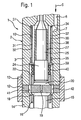
- FIG. 1 is a section of a fuel injector 1 with an injector 2 shown in longitudinal section.
- the injector housing 2 comprises an injector body 3, which is also referred to as a holding body.
- a high-pressure fuel connection is indicated, passes through the high-pressure fuel in a high-pressure fuel passage 6, which is recessed in the holding body 3.
- the high-pressure fuel channel 6 opens into an orifice region 7 in a main bore 10, which extends in the interior of the holding body 3 in the longitudinal direction.
- the main bore 10 of the injector body or holding body 3 is closed by an intermediate plate 12.
- the intermediate plate 12 is clamped by means of a clamping nut 13 between a nozzle body 14 and the holding body 3.
- the nozzle body 14 protrudes with its lower end shown cut off into the combustion chamber of an internal combustion engine to be supplied with fuel.
- an axial guide bore is recessed, in which a nozzle needle 15 is guided axially displaceable.
- At the combustion chamber near the end of the nozzle needle 15 at least one injection hole is provided in a known manner, is injected by the high-pressure fuel from the nozzle body 14 into the combustion chamber of the internal combustion engine when the nozzle needle 15 lifts with its tip from an associated nozzle needle seat.
- a control chamber limiting sleeve 16 is guided under sealing action, which limits a control chamber 18.
- the control chamber 18 is connected via a through hole 19 with an actuator pressure chamber 20 in connection.
- the actuator pressure chamber 20 is delimited by a Aktordruckraumbegrenzungshülse 22, which is guided at the combustion chamber near the end of an actuator piston 24 of a piezoelectric actuator 25.
- the actuator pressure chamber 20 and the piezoelectric actuator 25 are subjected to high pressure. To protect the piezoelectric actuator 25, this is provided radially on the outside with an insulation 27.
- a filter element 30 is arranged, which is substantially in the form of a sleeve and therefore also referred to as a filter sleeve 30.
- the filter sleeve 30 is provided with a plurality of through holes 31, 32, the size of which is such that impurities, such as chips, do not pass through the filter element 30.
- the filter element 30 At its end remote from the combustion chamber, the filter element 30 has a collar 34 which bears against the holding body 3. At its end close to the combustion chamber, the filter element 30 has a further collar 35, which also bears against the holding body 3. In the axial direction between the collars 34, 35, which are also referred to as guide rings, and in the radial direction outside the filter element 30, an annular space 37 is formed, which is connected to the mouth region 7 of the high-pressure fuel channel 6. The annular space 37 is filled via the high-pressure fuel passage 6 with fuel, which is acted upon by high pressure.
- the high pressure fuel passes through the through holes 31, 32 of the filter element 30 in a further annular space 38 which is provided in the radial direction between the piezoelectric actuator 25 and the filter element 30.
- the filtered fuel then passes from the further annular space 38 into the interior of the holding body 3, ie towards the combustion chamber.
- a coupling ring 39 At the combustion chamber near the end of the filter element 30 and the collar 35 is a coupling ring 39 at. Between the coupling ring 39, which may be formed integrally with the filter element 30 and the collar 35, and the Aktordruckraumbegrenzungshülse 22 is a helical compression spring 40 clamped. By the biasing force of the helical compression spring 40, the filter element 30 is stably held in the illustrated position.
- the limited by the main bore 10 and acted upon by high pressure Aktorfactraum is connected via two through holes 41 and 42 which are recessed in the intermediate plate 12, with the interior of the nozzle body 14 in connection.
- the filter sleeve 30 rests with the collars or guide rings 34, 35 on the holding body 3. By the biasing force of the spring 40, the filter sleeve 30 is pressed in the axial direction of the holding body 3.
- FIGS. 2 to 4 For example, a fuel injector 51 is shown in various views similar to that in FIG FIG. 1 shown fuel injector 1 is similar. To denote the same or similar parts, the same reference numerals are used. To avoid repetition, the preceding description of the FIG. 1 directed. In the following, the differences between the two embodiments are mainly discussed.
- a filter sleeve 60 is arranged in the radial direction between the piezoelectric actuator 25 and the holding body 3.
- the filter sleeve 60 comprises, as in FIG. 4 is shown enlarged, a plurality of through holes 61, 62.
- the filter sleeve 60 At its combustion chamber remote end, the filter sleeve 60 has a guide ring 64 which rests against the holding body 3.
- the filter sleeve 60 has a guide ring 65 which abuts the actuator piston 24 is applied.
- annular space 67 is provided which communicates via the through holes 61, 62 in the filter sleeve 60 with another annular space 68 in connection, which is provided in the radial direction between the filter sleeve 60 and the holding body 3.
- a coupling ring 69 is clamped.
- the filter element 60 in the region of the mouth region 7 of the high-pressure fuel channel 6 is equipped with a feed funnel 72 which, as can be seen in FIG FIG. 3 sees, a through hole 73 has.
- the feed funnel 72 surrounds the mouth region 7 of the high-pressure fuel channel 6 so that the fuel from the high-pressure fuel passage 6 passes through the through hole 37 into the annular space 67. From the annular space 67, the fuel passes through the through holes 61, 62 in the filter element 60 into the further annular space 68, as in FIG FIG. 4 indicated by an arrow 78. From the further annular space 68 of the high-pressure fuel then passes into the interior of the nozzle body.
- filter sleeve 60 is flowed through radially from the inside out. This provides the advantage that the third dimension is taken into account. Thus, chips that have a relatively small diameter, but are relatively long, are stopped by the filter element 60.
- the in the FIGS. 1 to 4 shown filter elements generally provide the advantage that they have a good filtering effect, without taking advantage of pressure wave effects. The large area with the plurality of holes prevents wear of the filter element in its lifetime.
Landscapes
- Engineering & Computer Science (AREA)
- Chemical & Material Sciences (AREA)
- Combustion & Propulsion (AREA)
- Mechanical Engineering (AREA)
- General Engineering & Computer Science (AREA)
- Physics & Mathematics (AREA)
- Fluid Mechanics (AREA)
- Fuel-Injection Apparatus (AREA)
Claims (9)
- Injecteur de carburant comprenant un boîtier d'injecteur (2), qui comprend un raccord de carburant haute pression (5) et un espace de logement d'actionneur sollicité par une haute pression, dans lequel est disposé un actionneur (25), et comprenant un élément filtrant (30 ; 60), l'élément filtrant (30 ; 60) étant disposé dans le boîtier d'injecteur (2), caractérisé en ce que l'élément filtrant (30 ; 60) est disposé dans la direction radiale entre l'actionneur (25) et le boîtier d'injecteur (2) et présente la forme d'une douille ayant une pluralité de petits orifices de passage (31, 32 ; 61,62) lesquels sont parcourus par du carburant sollicité à haute pression pendant le fonctionnement de l'injecteur de carburant.
- Injecteur de carburant selon la revendication 1, caractérisé en ce que le diamètre des orifices de passage (31,32 ; 61,62) est de 20 à 40 µm.
- Injecteur de carburant selon l'une quelconque des revendications précédentes, caractérisé en ce que le raccord de carburant haute pression (5) est en liaison avec un espace annulaire (37) qui s'étend entre l'élément filtrant (30) et le boîtier d'injecteur (2).
- Injecteur de carburant selon la revendication 3, caractérisé en ce qu'un espace annulaire supplémentaire (38) s'étend entre l'élément filtrant (30) et l'actionneur (25).
- Injecteur de carburant selon l'une quelconque des revendications 1 ou 2, caractérisé en ce que le raccord de carburant haute pression (5) est en liaison avec un espace annulaire (67) qui s'étend entre l'actionneur (25) et l'élément filtrant (60).
- Injecteur de carburant selon la revendication 5, caractérisé en ce que l'élément filtrant (60) présente, à une extrémité, un entonnoir d'alimentation (72) dans lequel débouche un canal de carburant haute pression (6), lequel part du raccord de carburant haute pression (5).
- Injecteur de carburant selon la revendication 5 ou 6, caractérisé en ce qu'un espace annulaire supplémentaire (68) s'étend entre l'élément filtrant (60) et le boîtier d'injecteur (2).
- Injecteur de carburant selon l'une quelconque des revendications précédentes, caractérisé en ce qu'une bague de guidage (34,35 ; 64,65) est montée à au moins une extrémité de l'élément filtrant (30 ; 60).
- Injecteur de carburant selon l'une quelconque des revendications 3 à 8, caractérisé en ce que l'espace annulaire (37 ; 67) et/ou l'espace annulaire supplémentaire (38 ; 68) présente(nt) dans la direction radiale une étendue de 100 à 200 µm.
Applications Claiming Priority (2)
| Application Number | Priority Date | Filing Date | Title |
|---|---|---|---|
| DE102006014243A DE102006014243A1 (de) | 2006-03-28 | 2006-03-28 | Kraftstoffinjektor |
| PCT/EP2007/051327 WO2007110268A1 (fr) | 2006-03-28 | 2007-02-12 | Élément filtrant dans un injecteur de carburant |
Publications (2)
| Publication Number | Publication Date |
|---|---|
| EP2002114A1 EP2002114A1 (fr) | 2008-12-17 |
| EP2002114B1 true EP2002114B1 (fr) | 2010-11-24 |
Family
ID=37983273
Family Applications (1)
| Application Number | Title | Priority Date | Filing Date |
|---|---|---|---|
| EP07726349A Not-in-force EP2002114B1 (fr) | 2006-03-28 | 2007-02-12 | Élément filtrant dans un injecteur de carburant |
Country Status (4)
| Country | Link |
|---|---|
| EP (1) | EP2002114B1 (fr) |
| AT (1) | ATE489555T1 (fr) |
| DE (2) | DE102006014243A1 (fr) |
| WO (1) | WO2007110268A1 (fr) |
Families Citing this family (3)
| Publication number | Priority date | Publication date | Assignee | Title |
|---|---|---|---|---|
| FR3051229B1 (fr) * | 2016-05-13 | 2021-02-19 | Delphi Int Operations Luxembourg Sarl | Injecteur de carburant pour moteur a combustion interne |
| DE102017123416A1 (de) * | 2017-10-09 | 2019-04-11 | Woodward L'orange Gmbh | Kraftstoffinjektor sowie Einspritzsystem für eine Brennkraftmaschine |
| US10941742B2 (en) | 2018-04-09 | 2021-03-09 | Caterpillar Inc. | Perforated integral filter sleeve for fuel injector and fuel system setup method |
Family Cites Families (4)
| Publication number | Priority date | Publication date | Assignee | Title |
|---|---|---|---|---|
| US2376292A (en) * | 1941-09-26 | 1945-05-15 | Reconstruction Finance Corp | Fuel injection nozzle |
| US3391680A (en) * | 1965-09-01 | 1968-07-09 | Physics Internat Company | Fuel injector-ignitor system for internal combustion engines |
| JPH02122164U (fr) * | 1989-03-18 | 1990-10-05 | ||
| JPH08218974A (ja) * | 1995-02-17 | 1996-08-27 | Keihin Seiki Mfg Co Ltd | 電磁式燃料噴射弁 |
-
2006
- 2006-03-28 DE DE102006014243A patent/DE102006014243A1/de not_active Withdrawn
-
2007
- 2007-02-12 EP EP07726349A patent/EP2002114B1/fr not_active Not-in-force
- 2007-02-12 DE DE502007005756T patent/DE502007005756D1/de active Active
- 2007-02-12 WO PCT/EP2007/051327 patent/WO2007110268A1/fr not_active Ceased
- 2007-02-12 AT AT07726349T patent/ATE489555T1/de active
Also Published As
| Publication number | Publication date |
|---|---|
| DE502007005756D1 (de) | 2011-01-05 |
| WO2007110268A1 (fr) | 2007-10-04 |
| ATE489555T1 (de) | 2010-12-15 |
| EP2002114A1 (fr) | 2008-12-17 |
| DE102006014243A1 (de) | 2007-10-04 |
Similar Documents
| Publication | Publication Date | Title |
|---|---|---|
| DE3217844A1 (de) | Kraftstoffeinspritzduese fuer dieselmaschinen | |
| EP2331806B1 (fr) | Injecteur comportant un filtre à particules disposé en amont de la restriction d'admission | |
| EP0977943B1 (fr) | Systeme d'injection de carburant pour moteurs a combustion interne | |
| EP2108080A1 (fr) | Injecteur pour injecter du carburant dans les chambres de combustion des moteurs à combustion interne | |
| EP1370765B1 (fr) | Soupape d'injection de carburant | |
| EP1395744B1 (fr) | Appareil d'injection de carburant pour moteurs a combustion, en particulier injecteur de type common rail, systeme d'alimentation en carburant et moteur a combustion | |
| EP1395749B1 (fr) | Soupape d'injection de carburant | |
| EP1963659B1 (fr) | Injecteur de carburant dote d'un organe de soupape d'injection a actionnement direct | |
| DE102005035347B3 (de) | Kraftstoffinjektor | |
| EP0900334A1 (fr) | Soupape de refoulement | |
| EP2002114B1 (fr) | Élément filtrant dans un injecteur de carburant | |
| DE102008001425A1 (de) | Kraftstoff-Einspritzvorrichtung | |
| DE10247958A1 (de) | Kraftstoff-Einspritzvorrichtung für eine Brennkraftmaschine | |
| DE19609218B4 (de) | Kraftstoffeinspritzventil für Brennkraftmaschinen | |
| EP1910663B1 (fr) | Systeme d'injection de carburant pour moteur a combustion interne a injection directe de carburant | |
| WO1997033085A1 (fr) | Soupape d'injection de carburant pour moteurs a combustion interne | |
| EP1840366B1 (fr) | Injecteur de carburant | |
| DE102008041167A1 (de) | Kraftstoffinjektor | |
| EP1740822B1 (fr) | Injecteur common rail | |
| DE2926382A1 (de) | Kraftstoffeinspritzvorrichtung mit einer einspritzduese | |
| DE102007029793A1 (de) | Kraftstoffinjektor | |
| EP1003964A1 (fr) | Soupape d'injection de carburant | |
| DE102010039116A1 (de) | Kraftstoffinjektor | |
| DE102004024528A1 (de) | Kraftstoffeinspritzsystem | |
| DE10164395A1 (de) | Kraftstoffeinspritzvorrichtung für Brennkraftmaschinen |
Legal Events
| Date | Code | Title | Description |
|---|---|---|---|
| PUAI | Public reference made under article 153(3) epc to a published international application that has entered the european phase |
Free format text: ORIGINAL CODE: 0009012 |
|
| 17P | Request for examination filed |
Effective date: 20081028 |
|
| AK | Designated contracting states |
Kind code of ref document: A1 Designated state(s): AT BE BG CH CY CZ DE DK EE ES FI FR GB GR HU IE IS IT LI LT LU LV MC NL PL PT RO SE SI SK TR |
|
| 17Q | First examination report despatched |
Effective date: 20090907 |
|
| GRAP | Despatch of communication of intention to grant a patent |
Free format text: ORIGINAL CODE: EPIDOSNIGR1 |
|
| DAX | Request for extension of the european patent (deleted) | ||
| GRAS | Grant fee paid |
Free format text: ORIGINAL CODE: EPIDOSNIGR3 |
|
| GRAA | (expected) grant |
Free format text: ORIGINAL CODE: 0009210 |
|
| AK | Designated contracting states |
Kind code of ref document: B1 Designated state(s): AT BE BG CH CY CZ DE DK EE ES FI FR GB GR HU IE IS IT LI LT LU LV MC NL PL PT RO SE SI SK TR |
|
| REG | Reference to a national code |
Ref country code: GB Ref legal event code: FG4D Free format text: NOT ENGLISH |
|
| REG | Reference to a national code |
Ref country code: CH Ref legal event code: EP |
|
| REG | Reference to a national code |
Ref country code: IE Ref legal event code: FG4D |
|
| REF | Corresponds to: |
Ref document number: 502007005756 Country of ref document: DE Date of ref document: 20110105 Kind code of ref document: P |
|
| REG | Reference to a national code |
Ref country code: NL Ref legal event code: VDEP Effective date: 20101124 |
|
| LTIE | Lt: invalidation of european patent or patent extension |
Effective date: 20101124 |
|
| PG25 | Lapsed in a contracting state [announced via postgrant information from national office to epo] |
Ref country code: LT Free format text: LAPSE BECAUSE OF FAILURE TO SUBMIT A TRANSLATION OF THE DESCRIPTION OR TO PAY THE FEE WITHIN THE PRESCRIBED TIME-LIMIT Effective date: 20101124 |
|
| PG25 | Lapsed in a contracting state [announced via postgrant information from national office to epo] |
Ref country code: PT Free format text: LAPSE BECAUSE OF FAILURE TO SUBMIT A TRANSLATION OF THE DESCRIPTION OR TO PAY THE FEE WITHIN THE PRESCRIBED TIME-LIMIT Effective date: 20110324 Ref country code: LV Free format text: LAPSE BECAUSE OF FAILURE TO SUBMIT A TRANSLATION OF THE DESCRIPTION OR TO PAY THE FEE WITHIN THE PRESCRIBED TIME-LIMIT Effective date: 20101124 Ref country code: BG Free format text: LAPSE BECAUSE OF FAILURE TO SUBMIT A TRANSLATION OF THE DESCRIPTION OR TO PAY THE FEE WITHIN THE PRESCRIBED TIME-LIMIT Effective date: 20110224 Ref country code: FI Free format text: LAPSE BECAUSE OF FAILURE TO SUBMIT A TRANSLATION OF THE DESCRIPTION OR TO PAY THE FEE WITHIN THE PRESCRIBED TIME-LIMIT Effective date: 20101124 Ref country code: CY Free format text: LAPSE BECAUSE OF FAILURE TO SUBMIT A TRANSLATION OF THE DESCRIPTION OR TO PAY THE FEE WITHIN THE PRESCRIBED TIME-LIMIT Effective date: 20101124 Ref country code: SE Free format text: LAPSE BECAUSE OF FAILURE TO SUBMIT A TRANSLATION OF THE DESCRIPTION OR TO PAY THE FEE WITHIN THE PRESCRIBED TIME-LIMIT Effective date: 20101124 Ref country code: SI Free format text: LAPSE BECAUSE OF FAILURE TO SUBMIT A TRANSLATION OF THE DESCRIPTION OR TO PAY THE FEE WITHIN THE PRESCRIBED TIME-LIMIT Effective date: 20101124 Ref country code: IS Free format text: LAPSE BECAUSE OF FAILURE TO SUBMIT A TRANSLATION OF THE DESCRIPTION OR TO PAY THE FEE WITHIN THE PRESCRIBED TIME-LIMIT Effective date: 20110324 Ref country code: NL Free format text: LAPSE BECAUSE OF FAILURE TO SUBMIT A TRANSLATION OF THE DESCRIPTION OR TO PAY THE FEE WITHIN THE PRESCRIBED TIME-LIMIT Effective date: 20101124 |
|
| REG | Reference to a national code |
Ref country code: IE Ref legal event code: FD4D |
|
| PG25 | Lapsed in a contracting state [announced via postgrant information from national office to epo] |
Ref country code: GR Free format text: LAPSE BECAUSE OF FAILURE TO SUBMIT A TRANSLATION OF THE DESCRIPTION OR TO PAY THE FEE WITHIN THE PRESCRIBED TIME-LIMIT Effective date: 20110225 |
|
| PG25 | Lapsed in a contracting state [announced via postgrant information from national office to epo] |
Ref country code: CZ Free format text: LAPSE BECAUSE OF FAILURE TO SUBMIT A TRANSLATION OF THE DESCRIPTION OR TO PAY THE FEE WITHIN THE PRESCRIBED TIME-LIMIT Effective date: 20101124 Ref country code: EE Free format text: LAPSE BECAUSE OF FAILURE TO SUBMIT A TRANSLATION OF THE DESCRIPTION OR TO PAY THE FEE WITHIN THE PRESCRIBED TIME-LIMIT Effective date: 20101124 Ref country code: ES Free format text: LAPSE BECAUSE OF FAILURE TO SUBMIT A TRANSLATION OF THE DESCRIPTION OR TO PAY THE FEE WITHIN THE PRESCRIBED TIME-LIMIT Effective date: 20110307 Ref country code: IE Free format text: LAPSE BECAUSE OF FAILURE TO SUBMIT A TRANSLATION OF THE DESCRIPTION OR TO PAY THE FEE WITHIN THE PRESCRIBED TIME-LIMIT Effective date: 20101124 |
|
| BERE | Be: lapsed |
Owner name: ROBERT BOSCH G.M.B.H. Effective date: 20110228 |
|
| PG25 | Lapsed in a contracting state [announced via postgrant information from national office to epo] |
Ref country code: SK Free format text: LAPSE BECAUSE OF FAILURE TO SUBMIT A TRANSLATION OF THE DESCRIPTION OR TO PAY THE FEE WITHIN THE PRESCRIBED TIME-LIMIT Effective date: 20101124 Ref country code: RO Free format text: LAPSE BECAUSE OF FAILURE TO SUBMIT A TRANSLATION OF THE DESCRIPTION OR TO PAY THE FEE WITHIN THE PRESCRIBED TIME-LIMIT Effective date: 20101124 Ref country code: DK Free format text: LAPSE BECAUSE OF FAILURE TO SUBMIT A TRANSLATION OF THE DESCRIPTION OR TO PAY THE FEE WITHIN THE PRESCRIBED TIME-LIMIT Effective date: 20101124 Ref country code: PL Free format text: LAPSE BECAUSE OF FAILURE TO SUBMIT A TRANSLATION OF THE DESCRIPTION OR TO PAY THE FEE WITHIN THE PRESCRIBED TIME-LIMIT Effective date: 20101124 |
|
| PG25 | Lapsed in a contracting state [announced via postgrant information from national office to epo] |
Ref country code: MC Free format text: LAPSE BECAUSE OF NON-PAYMENT OF DUE FEES Effective date: 20110228 |
|
| PLBE | No opposition filed within time limit |
Free format text: ORIGINAL CODE: 0009261 |
|
| REG | Reference to a national code |
Ref country code: CH Ref legal event code: PL |
|
| STAA | Information on the status of an ep patent application or granted ep patent |
Free format text: STATUS: NO OPPOSITION FILED WITHIN TIME LIMIT |
|
| GBPC | Gb: european patent ceased through non-payment of renewal fee |
Effective date: 20110224 |
|
| PG25 | Lapsed in a contracting state [announced via postgrant information from national office to epo] |
Ref country code: CH Free format text: LAPSE BECAUSE OF NON-PAYMENT OF DUE FEES Effective date: 20110228 Ref country code: LI Free format text: LAPSE BECAUSE OF NON-PAYMENT OF DUE FEES Effective date: 20110228 |
|
| 26N | No opposition filed |
Effective date: 20110825 |
|
| PG25 | Lapsed in a contracting state [announced via postgrant information from national office to epo] |
Ref country code: BE Free format text: LAPSE BECAUSE OF NON-PAYMENT OF DUE FEES Effective date: 20110228 |
|
| REG | Reference to a national code |
Ref country code: DE Ref legal event code: R097 Ref document number: 502007005756 Country of ref document: DE Effective date: 20110825 |
|
| PG25 | Lapsed in a contracting state [announced via postgrant information from national office to epo] |
Ref country code: IT Free format text: LAPSE BECAUSE OF FAILURE TO SUBMIT A TRANSLATION OF THE DESCRIPTION OR TO PAY THE FEE WITHIN THE PRESCRIBED TIME-LIMIT Effective date: 20101124 |
|
| PG25 | Lapsed in a contracting state [announced via postgrant information from national office to epo] |
Ref country code: GB Free format text: LAPSE BECAUSE OF NON-PAYMENT OF DUE FEES Effective date: 20110224 |
|
| REG | Reference to a national code |
Ref country code: AT Ref legal event code: MM01 Ref document number: 489555 Country of ref document: AT Kind code of ref document: T Effective date: 20120212 |
|
| PG25 | Lapsed in a contracting state [announced via postgrant information from national office to epo] |
Ref country code: LU Free format text: LAPSE BECAUSE OF NON-PAYMENT OF DUE FEES Effective date: 20110212 |
|
| PG25 | Lapsed in a contracting state [announced via postgrant information from national office to epo] |
Ref country code: AT Free format text: LAPSE BECAUSE OF NON-PAYMENT OF DUE FEES Effective date: 20120212 |
|
| PG25 | Lapsed in a contracting state [announced via postgrant information from national office to epo] |
Ref country code: TR Free format text: LAPSE BECAUSE OF FAILURE TO SUBMIT A TRANSLATION OF THE DESCRIPTION OR TO PAY THE FEE WITHIN THE PRESCRIBED TIME-LIMIT Effective date: 20101124 |
|
| PG25 | Lapsed in a contracting state [announced via postgrant information from national office to epo] |
Ref country code: HU Free format text: LAPSE BECAUSE OF FAILURE TO SUBMIT A TRANSLATION OF THE DESCRIPTION OR TO PAY THE FEE WITHIN THE PRESCRIBED TIME-LIMIT Effective date: 20101124 |
|
| REG | Reference to a national code |
Ref country code: FR Ref legal event code: PLFP Year of fee payment: 10 |
|
| PGFP | Annual fee paid to national office [announced via postgrant information from national office to epo] |
Ref country code: FR Payment date: 20160222 Year of fee payment: 10 |
|
| PGFP | Annual fee paid to national office [announced via postgrant information from national office to epo] |
Ref country code: DE Payment date: 20160426 Year of fee payment: 10 |
|
| REG | Reference to a national code |
Ref country code: DE Ref legal event code: R119 Ref document number: 502007005756 Country of ref document: DE |
|
| REG | Reference to a national code |
Ref country code: FR Ref legal event code: ST Effective date: 20171031 |
|
| PG25 | Lapsed in a contracting state [announced via postgrant information from national office to epo] |
Ref country code: FR Free format text: LAPSE BECAUSE OF NON-PAYMENT OF DUE FEES Effective date: 20170228 Ref country code: DE Free format text: LAPSE BECAUSE OF NON-PAYMENT OF DUE FEES Effective date: 20170901 |