EP2002204B1 - Procede et dispositif de determination et de mesure d'ecarts de forme et d'ondulations sur des pieces a symetrie de rotation - Google Patents
Procede et dispositif de determination et de mesure d'ecarts de forme et d'ondulations sur des pieces a symetrie de rotation Download PDFInfo
- Publication number
- EP2002204B1 EP2002204B1 EP07723569A EP07723569A EP2002204B1 EP 2002204 B1 EP2002204 B1 EP 2002204B1 EP 07723569 A EP07723569 A EP 07723569A EP 07723569 A EP07723569 A EP 07723569A EP 2002204 B1 EP2002204 B1 EP 2002204B1
- Authority
- EP
- European Patent Office
- Prior art keywords
- rotation
- test part
- measuring
- light beam
- angle
- Prior art date
- Legal status (The legal status is an assumption and is not a legal conclusion. Google has not performed a legal analysis and makes no representation as to the accuracy of the status listed.)
- Not-in-force
Links
- 238000000034 method Methods 0.000 title claims abstract description 54
- 238000012360 testing method Methods 0.000 claims abstract description 57
- 238000001914 filtration Methods 0.000 claims abstract description 14
- 238000006073 displacement reaction Methods 0.000 claims abstract description 13
- 238000004458 analytical method Methods 0.000 claims abstract description 10
- 230000003287 optical effect Effects 0.000 claims description 14
- 238000011156 evaluation Methods 0.000 claims description 5
- 238000010219 correlation analysis Methods 0.000 claims description 4
- 238000004590 computer program Methods 0.000 claims 1
- 230000002596 correlated effect Effects 0.000 claims 1
- 238000005259 measurement Methods 0.000 abstract description 68
- 230000005855 radiation Effects 0.000 abstract 1
- 238000005286 illumination Methods 0.000 description 12
- 238000005311 autocorrelation function Methods 0.000 description 6
- 230000005693 optoelectronics Effects 0.000 description 5
- 238000005070 sampling Methods 0.000 description 5
- 238000012937 correction Methods 0.000 description 4
- 238000003754 machining Methods 0.000 description 4
- 230000010287 polarization Effects 0.000 description 4
- 230000011514 reflex Effects 0.000 description 4
- 239000000523 sample Substances 0.000 description 4
- 238000004364 calculation method Methods 0.000 description 3
- 238000010586 diagram Methods 0.000 description 3
- 230000010354 integration Effects 0.000 description 3
- 238000000691 measurement method Methods 0.000 description 3
- 230000005540 biological transmission Effects 0.000 description 2
- 238000004422 calculation algorithm Methods 0.000 description 2
- 230000001419 dependent effect Effects 0.000 description 2
- 238000001514 detection method Methods 0.000 description 2
- 230000005489 elastic deformation Effects 0.000 description 2
- 230000007613 environmental effect Effects 0.000 description 2
- 230000005484 gravity Effects 0.000 description 2
- 238000004519 manufacturing process Methods 0.000 description 2
- 230000010355 oscillation Effects 0.000 description 2
- 230000000737 periodic effect Effects 0.000 description 2
- 230000008569 process Effects 0.000 description 2
- 238000012545 processing Methods 0.000 description 2
- 238000001228 spectrum Methods 0.000 description 2
- 230000001629 suppression Effects 0.000 description 2
- 230000009466 transformation Effects 0.000 description 2
- 238000013459 approach Methods 0.000 description 1
- 230000008901 benefit Effects 0.000 description 1
- 230000033228 biological regulation Effects 0.000 description 1
- 230000001427 coherent effect Effects 0.000 description 1
- 238000010276 construction Methods 0.000 description 1
- 238000005520 cutting process Methods 0.000 description 1
- 238000007405 data analysis Methods 0.000 description 1
- 230000001627 detrimental effect Effects 0.000 description 1
- 230000000694 effects Effects 0.000 description 1
- 238000005516 engineering process Methods 0.000 description 1
- 238000000605 extraction Methods 0.000 description 1
- 238000003384 imaging method Methods 0.000 description 1
- 230000006872 improvement Effects 0.000 description 1
- 239000000463 material Substances 0.000 description 1
- 238000010606 normalization Methods 0.000 description 1
- 230000003071 parasitic effect Effects 0.000 description 1
- 238000009304 pastoral farming Methods 0.000 description 1
- 238000003908 quality control method Methods 0.000 description 1
- 238000005096 rolling process Methods 0.000 description 1
- 238000007789 sealing Methods 0.000 description 1
- 238000000926 separation method Methods 0.000 description 1
- 238000004088 simulation Methods 0.000 description 1
- 125000006850 spacer group Chemical group 0.000 description 1
- 230000003068 static effect Effects 0.000 description 1
- 238000003860 storage Methods 0.000 description 1
- 239000012780 transparent material Substances 0.000 description 1
- 230000004304 visual acuity Effects 0.000 description 1
Images



Classifications
-
- G—PHYSICS
- G01—MEASURING; TESTING
- G01B—MEASURING LENGTH, THICKNESS OR SIMILAR LINEAR DIMENSIONS; MEASURING ANGLES; MEASURING AREAS; MEASURING IRREGULARITIES OF SURFACES OR CONTOURS
- G01B11/00—Measuring arrangements characterised by the use of optical techniques
- G01B11/24—Measuring arrangements characterised by the use of optical techniques for measuring contours or curvatures
- G01B11/2408—Measuring arrangements characterised by the use of optical techniques for measuring contours or curvatures for measuring roundness
Definitions
- the invention relates to a method and a device for determining and measuring deviations in shape and ripples on rotationally symmetrical technical surfaces in the circumferential direction, which quickly detect and evaluate deviations in form and waviness with little effort and high stability against disturbing environmental influences.
- Rotationally symmetric surfaces are technically mostly used as static or dynamic sealing surfaces or as sliding or rolling surfaces. Shape deviations 1st and 2nd order (shape deviation and waviness) thus have a particularly detrimental effect on the functional behavior of these surfaces. Consequently, particularly high quality criteria with regard to shape deviation and waviness apply to rotationally symmetrical workpieces.
- Form deviations in machining processes result mostly from the elastic deformation of the processing unit (tool, tool holder, etc.), the elastic deformation of the workpiece or guideway errors of the tool or workpiece during processing. Ripples are caused by vibrations of the tool or workpiece during chip removal. The influence of these disturbances on the shape deviations 1st and 2nd order depends in a complex way on a number of technological parameters of the machining process (eg the cutting conditions during chip removal, the workpiece material, etc.). In order to evaluate the surface function of the machined workpiece and to allow an analysis of the machining process, a quick measurement of these shape deviations is desirable.
- Shape deviations and ripples of rotationally symmetrical surfaces are measured according to the prior art primarily with the aid of tactile Formprüfön. Under laboratory conditions, these stylus methods allow to detect deviations in shape with high precision. However, these measuring devices require a complex adjustment of the test specimen and high measuring times.
- Autofocus methods and triangulation methods measure pointwise height differences with respect to an ideal track.
- the vertical resolution is substantially determined by the angle of incidence of the measuring light beam and the magnification of the measuring objective. If the triangulated method uses only the scattered light of the test object as a measuring signal (eg US 4,373,804 ), a vertical resolution of a maximum of 0.1 microns or 0.005% of the measuring range is reached, which is sufficient for shape measurement but does not allow a precise ripple analysis. Furthermore, the method for reflective surfaces can not be used. Is the triangulation method based on the measurement of the direct reflex (eg US 2002/0145740 ), a vertical resolving power in the nanometer range can be realized, but the method is limited to specular surfaces with a small vertical measuring range.
- Autofocus sensors measure the height of an illuminated surface point to a reference path with high vertical resolution with a large measuring range (see eg EP 0271646 B1 ), however, require long measurement times on rough surfaces since the focal point position varies greatly due to the roughness of the specimen surface and an adjustment of the objective is necessary for each measurement point.
- the main disadvantage of the triangulation and autofocus methods is that the guideway errors are incorporated directly into the measurement result, and the methods thus require precision turntables for the test piece rotation and an accurate adjustment of the test object.
- vibrations of the measuring system and / or the test object are to be avoided and consequently accurate measurement results can only be achieved under laboratory conditions.
- a measuring light beam illuminates the specimen surface at a defined angle of incidence ⁇ i (cf. Fig. 1 ).
- the light beam reflected by the specimen surface can be registered in a plane S and the deflection X of the reflected light bundle to a calibrated zero position S 0 can be detected and evaluated.
- the zero position of a receiver located in the plane S indicates the reflection angle ⁇ r of an ideally flat surface F 0 lying in the scanning path and its surface normal n 0 correspond to the gradient of the Tastbahn.
- a lateral offset X to the zero position on the position receiver results whenever the local gradient n n of the illuminated real surface profile F r deviates from the Tastbahngradienten. This offset is proportional to the day of the difference angle ⁇ r, n , from which, according to the law of reflection, the local inclination angle d ⁇ n can be calculated.
- the test object surface F r is scanned with a given scanning step dx and the profile of the test object is calculated by integration of the local surface slopes d ⁇ n .
- the local inclination angle of the illuminated surface can be increased by a multiple compared to guideway errors (eg height offset to the tactile path) at a long optical path of the reflected light beam.
- the method is also insensitive to vertical vibrations of the specimen (see, eg DE 3503858 A1 . DE 202004009727 U1 ) and additionally enables the determination of the roughness, if the scattering behavior of the reflected light bundle is measured angularly resolved, eg with a CCD line ( US 4,859,062 ).
- the influence of the eccentricity and vertical vibrations on the profile height determination according to the above-quoted angle measurement method is not critical.
- the first Fourier component introduced by the eccentricity can be filtered out of the height profile, while short-wave vertical oscillation components, due to the short integration intervals, remain almost unnoticed in the measurement result.
- the eccentricity of the sample also leads to distortion of the sampling points in the circumferential direction.
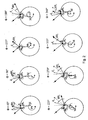
- the resulting influence of the eccentricity on the reflection behavior of the measuring beam during a full rotation of the test object is exemplary in FIG FIG. 2 clarified.
- a cylinder section to be examined for example a shaft, is shown as a circle in several rotational phases, wherein it is rotated with the circle center M about the axis of rotation P.
- the amplitude of the eccentricity results from the distance between P and M.
- the real angle scan on the surface of the device under test varies with eccentricity.
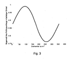
- the profile heights determined by means of differential angle measurement DUT therefore do not result from an equidistant scan of the circumference of the cylinder, but from Tastabofficen which vary sinusoidally by an average value depending on the azimuthal position of the eccentricity, which in FIG. 3 is shown.
- this distortion is critical because it leads to a frequency band extension, which prevents a determination of the real existing main frequency from the Fourier spectrum of the circumferential profile.
- a compact device for distance determination by means of a triangulation method is disclosed in US Pat US 4,596,460 presented.
- a focusing lens images the off-axis beam of the illumination source onto a specimen surface.
- a roof edge prism aligned with the lens is used for beam deflection.
- a roof side of the prism directs the illumination beam path so that the convergent illumination light beam is incident on the specimen surface at a defined angle of incidence.
- the reflected light beam at the specimen surface is received via the same prism and returned to the other side of the roof prism.
- the compact optical concept requires a very precise adjustment of all optical components to each other, which is complicated and prone to failure, especially because of the off-axis beam. A simplification of the adjustment would result if the optical components are combined by means of precise mechanical spacers. However, the production of such components is complicated and expensive.
- a simple compact sensor for optically controlling a surface condition is disclosed in US Pat EP 0 628 787 A2 presented.
- a grazing light beam is reflected and scattered by the specimen surface.
- the intensities of the vertically and parallel polarized light of the directly reflected light beam are detected and set in relation to one another.
- a prism be used, wherein a polarization beam splitter splits the two polarization components and deflects with a mirror layer on another prism surface.
- the beam offset of the two polarization components introduced by the polarization beam splitter plate and mirror layer can be used to place two receivers directly on the prism surface which measure the intensities separately.
- the prism serves as a reference body for defined beam deflection and detection.
- the prism angles, as proposed there, are not suitable for effecting a targeted interference light suppression.
- the prism angles indicate the reference coordinates of the measuring system. For example, a prism surface as a contact surface for a Receiver unit used. Furthermore, parasitic reflections can be minimized or eliminated by optimizing the prism angle.
- this arrangement relates to the measurement of a path difference based on two reflected beams for determining the thickness of optically transparent materials.
- the present invention is therefore based on the object of specifying a method and a device suitable for carrying out the method, which do not have the above-described disadvantages of the prior art, with a small measurement effort and high stability to disturbing environmental influences quickly form deviations and ripples quantitatively detected and be evaluated, the optical state of the surfaces to be examined (highly reflective or rougher surfaces) without effect on the Are method and thus the proposed solution in near-process or in-process can be used advantageously.
- a lighting device illuminates the rotationally symmetrical surface to be examined in a defined angle of incidence ⁇ i in the circumferential direction.
- the center of gravity of the light beam reflected from the surface is determined by means of a position sensitive optoelectronic sensor detected.
- the measuring light bundle reflected at the angle ⁇ r, n is a function of the local surface gradient of the illuminated surface area n deflected.
- the angular difference between the real and the ideal reflection angle ⁇ r, n - ⁇ r (ideally the surface gradient is n 0 perpendicular to the scanning path) is measured on the position-sensitive surface S of the optoelectronic receiver as a path difference X (see. Fig. 1 ).
- This deflection is recorded, for example, at least two closed revolutions of the test specimen with equidistant angular increments about the axis of rotation P.
- the measured position signals X can be converted into reflection angles ⁇ r, n . After the law of reflection ⁇ r .
- n ⁇ j + 2 ⁇ d ⁇ ⁇ , n - ⁇ i .
- ⁇ r, n the local reflection angle and ⁇ i are the angle of incidence of the measuring light beam
- the local surface tilt angle d ⁇ n of the specimen can be determined in the circumferential direction.
- Local errors of the guideway eg concentricity error of educalingsspannvorraum
- ripples due to bearing clearance of the tensioning device and high-frequency oscillations between specimen surface and sensor affect the accuracy of the measured values only slightly, since due to the long "lever arm" of the reflected Meßlichtbündels the measurement signal detects primarily angular changes of the direct reflex.
- the measurement signal d ⁇ r ( ⁇ ) is composed of a short-wave local deviation of the surface gradient n n to the vertical ideal trajectory normal n 0 , which causes the ripple or shape deviation of the real surface profile, and a long-wave deviation of the normal n c too n 0 , which is introduced by the eccentricity (cf to the above Fig. 2 ).
- the long-wave components of the measurement signal d ⁇ e ( ⁇ ) are used directly for the correction.
- the long-wave slope values d ⁇ e are calculated for each rotation angle value ⁇ according to the law of reflection.
- the angular displacement d ⁇ e corresponds exactly to the distortion of the equidistant Winkelabtastung eccentric rotation of a DUT.
- the measured angle differences are thus a function d ⁇ r ( ⁇ + d ⁇ e ).
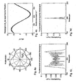
- Fig. 4 The influence of the eccentricity on an uncorrected and a corrected signal clarifies Fig. 4 .
- a cylinder is assumed which has a waviness of 200 waves per circumference with an amplitude of 500 nm and a shape deviation of three waves per circumference with an amplitude of 5 ⁇ m, which is eccentrically rotated, the displacement between the rotation axis P and the center of the circle M should be one tenth of the cylinder radius.
- Fig. 4a shows the profile deviation of the cylinder from the ideal circular shape in a coated representation.
- the resulting angular displacement of a measurement beam for equidistant angular scanning about P is in Fig. 4b shown.
- the non-contact optical angle measurement on cylindrical samples enables high measuring speeds, it is advantageous to carry out the measurement for several revolutions. If a uniform rotational movement can be assumed, an equidistant angle scanning without precise angle tables is possible.
- an external clocking eg a rectangular pulse generator
- the angular value of the rotating DUT is sampled at a fixed frequency.
- a position-sensitive photodiode PSD is used as the position-sensitive receiver, as is preferred in the context of this invention, two locally typical signals are obtained. The sum signal of the PSD detects the total intensity of the light reflected from the specimen and thus the local reflection coefficient.
- the difference signal of the PSD characterizes the local angular excursion of the direct reflex and thus the local inclination angle of the real profile.
- Both signals are suitable for correlation analysis to determine the number of tactile points of a full revolution and thus the angular increment of the measurement.
- both signals it is possible for both rough and highly reflective surfaces to perform precise profile determinations in the circumferential direction with external clocking for multiple revolutions.
- the method is well suited for in-process measurement during machining of rotationally symmetric parts.
- the systematically occurring rotation angle-dependent signals can be identified as periodic functions and can be separated from all random measurement errors by means of signal filtering.
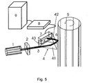
- FIG. 5 schematically illustrates the basic structure of a device designed for this purpose, will be explained.
- a laser diode 1 emits a light beam 3, which is focused with the aid of an optical system 2 onto a test object surface 5 which can be displaced in rotational movements.
- a cylindrical lens is favorably chosen for the measurement of rough surfaces, since, due to the line illumination in the case of small line widths in the circumferential direction, it is possible to average over the speckle structure of the reflected light bundle 6 with the aid of the receiver surface of a position-sensitive optoelectronic receiver 7. This leads to an improved focus determination of the reflected light bundle 6 with coherent noise of the bundle and thus enables a differential angle measurement on rough cylindrical scholarlingsobervid.
- the central optical component of the claimed device is a prism 4 arranged in the beam path, which deflects both the incident light beam 3 and the light beam 6 reflected by the specimen surface.
- a prism 4 arranged in the beam path, which deflects both the incident light beam 3 and the light beam 6 reflected by the specimen surface.
- the adjustment process of the optics is simplified, since the prism 4 can serve as an angle reference system.
- the prism surfaces which include precise prism angles, are reference surfaces for an optoelectronic receiver 7 and the illumination optics with laser diode 1 and focus optics 2.
- the prism surface onto which the reflected light beam 6 passes is selected within the scope of the invention as a direct contact surface for the receiver 7.
- the direct reflection at the first refracting prism surface in the incident beam path can be used for adjustment and accurate Alignment of the optical axis of the lighting system can be used.
- the test object 5 rotates with a known angular increment or uniformly, as described in more detail in the method, about a rotation axis P which should lie in the vicinity of the cross-section center M of the test object 5 and is aligned parallel to the test object axis.
- the readout of the optoelectronic receiver 7 takes place via a measurement data acquisition unit 8, which amplifies, digitizes and stores the measured values.
- the measurement data acquisition unit 8 further realizes the synchronization of the measured value recording with the rotation of the test object.
- the synchronization can be carried out with uniform rotational movement of the specimen via an external or internal clock or at defined Winkei suits ein the specimen via a direct control of the data acquisition unit 8 by signals of a conventional motor controller from the rotary motor of educalingsrea.
- the measurement data are transmitted to an evaluation unit 9, which performs the calculation of ripple and shape deviation parameters in a manner described later, displays these parameters, logged and optionally compared with tolerance specifications and for control of an automatic quality control process forwards to a control unit.
- the assignment of the measured values to equidistant angular increments with uniform test specimen rotation takes place via the correlation analysis of the measurement signals described in accordance with the invention for at least two revolutions of the test specimen. Occurring eccentricities in theticiansrotation be compensated by the inventive method and in the last step, the measured difference angle converted into profile heights from which the evaluation unit 9 calculates the necessary ripple and shape deviation parameters.
- a gear shaft with a diameter of 44.7mm is quasi centric taken in the example with the help of a three-jaw chuck and set by rotation of the three-jaw chuck through a turntable in a uniform rotation.
- the optical measuring head according to the invention is delivered radially to the rotating shaft until the measuring head has reached the optimum operating point. This position can be approached automatically by detecting the signals of the receiver unit, since at the optimum working distance of the measuring head, the light reflected on the striglingswelle light illuminates the receiver 7 in the zero position.
- the total intensity of the light incident on the receiver (hereinafter referred to as the sum signal) is high, and the center of gravity of the reflected light beam 6 illuminates the receiver surface in the center so that the position-dependent signal of the PSD is zero (hereinafter referred to as differential signal). If the optimum working distance of the measuring head to the test piece surface is set, the measured value is recorded.
- a measurement clock is activated, which detects the measurement signals at a fixed frequency and a storage unit 8 feeds.
- the measurement clock generator is, for example, an external square-wave generator that controls the acquisition of measured values via the trigger input of a PC measurement card.
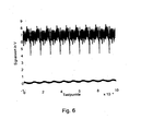
- FIG. 6 shows the measured signals of the PSD thus recorded for a uniformly rotating gear shaft with a diameter of 44.7 mm.
- the sampling frequency was 50kHz.
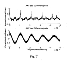
- FIG. 7 show the Autocorrelation functions of the waveforms FIG. 6 .
- the autocorrelation coefficient is a measure of the self-similarity of a function in its lateral displacement. The coefficient reaches a maximum when the gradients of the shifted and unshifted function become virtually congruent, which is achieved when shifting by one revolution. This maximum repeats periodically at each additional completed rotation position. For the example shown, this results in a Tast Vietnameseress per admirlingsumfitung of 10691. Since the transmission shaft has a ripple, the autocorrelation function of the difference signal is superimposed by a short-wave periodic function, but also has significant maxima at the positions of the completed revolutions.
- the maximums of the autocorrelation functions are determined and from whose positions the number of scanning points per test piece revolution is calculated.
- the lower limit frequency of the measuring signal is defined by the number of revolutions. If several revolutions have been measured, all longer-term components in the signal are due to measurement errors.
- these interference signals can be removed from both the sum and the difference signal. In order to suppress measurement errors whose frequency components are in the frequency band of the measurement signals, further filtering is performed after the high-pass filtering of the signals.
- the sum and the difference signal are split into signal sections whose respective lengths correspond exactly to one test piece rotation. These signal sections are Fourier-transformed and the absolute parts of the Fourier components are calculated. For both the sum and difference signals, it is thus possible to generate as many Fourier functions as revolutions were measured.
- the Fourier components of the actual measurement signal must be contained in all Fourier functions of the individual revolutions.
- the Fourier components with the smallest amplitude amount contained in all subfunctions are now to be added a Fourier réelle composed and generated from this by back transformation of the filtered waveform.
- the intensity-independent deflection signal can be converted directly into a reflection angle signal d ⁇ r ( ⁇ ) and the local surface tilt angle d ⁇ n can be determined according to the known reflection equation.
- FIG. 8 shows in the upper diagram the tilt angle signal calculated from the calibration data of the measurement Fig. 6 and 7 , The eccentricity of the measurement is included in the waveform.
- the eccentric tilt angle shift can be determined (cf. Fig. 8 lower picture). This corresponds exactly to the sampling point distortion according to the invention with eccentric rotation of a test object.
- the measurement signal d ⁇ n must be interpolated.
- the surface sampling of the specimen realized during the measurement was carried out at the angle values ⁇ + d ⁇ e ( ⁇ ), wherein the rotational angle values for ⁇ are in the interval 0 ° to 360 ° with angular increments of 360 ° / (measuring point number per revolution) (in the illustrated example the theoretical angular increment is 0.0337 °).
- the measured values for an equidistant scan with the fixed angular increment of 360 ° / are determined.
- the influence of the eccentricity on the measurement signal is low.
- the maximum eccentric angular displacement d ⁇ e is slightly more than the measuring step size and thus leads to maximum step size distortions of approximately one angular step.
- the equalization of the signal values thus imperceptibly alters the signal behavior.
- the measured signal is composed of the local inclination angle difference (the actual measured variable) and the increasing spatial displacement due to the path deviation.
- a locus calculation based solely on the integration of tilt angles can not be used to determine the runout.
- FIG. 9 shows the influence of the measuring beam incidence angle on the phase and the amplitude of the eccentric inclination angle shift. If the specimen surface is illuminated vertically (dashed curve), d ⁇ e results exclusively on the inclination angle shift of the illumination location. The additional Tastbahnabweichung leads only to a life extension of the measurement signal, but causes no deflection of the reflected light beam on the position-sensitive receiver. With a known test specimen diameter D and a known number of angular steps per revolution N, which were obtained from the autocorrelation function or are known at an angle step adjustment, can be according to the equation z e .
- the maximum of z e , n indicates the concentricity error, which in the example chosen Fig. 9 17.4 ⁇ m. If the same test object is illuminated at an angle of incidence of 40 °, the angle difference measurement results in an increased measurement signal (cf. Fig. 9 , solid line). In addition, the maximum relative to the vertically illuminated measurement is exactly shifted by the angle of incidence.
- the measured curve is normalized to the ratio d ⁇ e ( ⁇ max - ⁇ i ) / d ⁇ e ( ⁇ max ), so that one obtains a damped curve whose maximum now carries the value d ⁇ e ( ⁇ max - ⁇ i ). From this curve, as described above, the profile heights z e, n can be calculated from which the concentricity error can be determined as shown. This approximation leads to good results in the determination of concentricity errors. With eccentricities of less than 10% relative to the radius of the test object, the maximum deviations for the concentricity error determination are less than 2% according to the above-described approximation method.
- the shape deviation and ripple analysis is largely based on the standardized procedure for Tastschnitttownen.
- the angular displacement d ⁇ e introduced by the eccentricity is added to the measurement signal d ⁇ n and interpolated.
- the thus corrected measured values d ⁇ n now relate exclusively to the local inclination angle differences of the specimen surface.
- d ⁇ j stands for the corrected profile slope value (freed from the influence of the eccentricity).
- the form deviation and the dominant waviness profiles from the profile z n can now be determined by known filter methods.
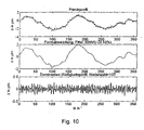
- the curve of z n corresponds to the primary profile (cf. Fig. 10 , top picture).
- a standardized low-pass filter here for example a Gaussian low pass with the cutoff wavelength of 50 waves per circumference
- the shape deviation according to VDA2007 the W profile
- the zero bandpass described in VDA2007 is used to generate the dominant ripple profiles.
- the dominant ripple profile is given at a wave number of 107 waves per revolution and in the bottom picture of Fig. 10 shown.
- the method and the device can be used for a large diameter range of about 1 mm to 2 m of rotationally symmetric test specimens.
- the only prerequisite is that the local surface slopes of the test object are small enough to be able to detect the reflected measuring light bundle in the predetermined measuring angle range of the measuring device.
- a prism with an edge length of 25 mm and a position-sensitive receiver (PSD) chosen and arranged according to the above specifications were sufficient. All of the above-mentioned calculations are realized by correspondingly provided numerical algorithms by means of corresponding PC programs in the evaluation unit 9.
Landscapes
- Physics & Mathematics (AREA)
- General Physics & Mathematics (AREA)
- Length Measuring Devices By Optical Means (AREA)
- Testing Of Optical Devices Or Fibers (AREA)
Claims (9)
- Procédé de détermination d'écarts de forme et/ou d'ondulations détectés sur les pièces à tester à symétrie de rotation, comprenant les opérations suivante :- tourner la pièce à tester autour de l'axe de symétrie,- diriger sur un plan perpendiculaire par rapport à l'axe de rotation un faisceau de lumière sur la circonférence de la pièce à tester,- enregistrer et sauvegarder les positions d'impact du faisceau de mesure réfléchi sur un récepteur sensible à la position en les attribuant de manière conforme à une séquence de positions théoriquement équidistantes d'angles de rotation Φi de la pièce à tester, pendant au moins une révolution complète de la pièce à tester,- ensuite procéder à un filtrage passe-bas de la courbe de mesure ainsi obtenue pour pouvoir déterminer les déviations du faisceau de lumière réfléchi, qui sont dues uniquement à l'excentricité de la pièce à tester par rapport à l'axe d'angle,- déterminer pour la séquence de positions d'angles de rotation théoriquement équidistantes Φi les décalages d'angle dus à l'excentricité dφe,i et les additionner aux positions d'angle théoriquement équidistantes Φi- attribuer les mesures des positions d'angle de rotation théoriquement équidistantes Φi aux positions d'angle de rotation corrigées (Φi, + dφe,i),- déteminer à l'aide d'une trame d'angles de rotations réellement équidistantes les valeurs d'interpolation de la courbe de mesures ainsi corrigée,- faire de la courbe des valeurs d'interpolation une analyse de Fourier qui représente directement l'ondulation dominante et /ou un filtrage passe-haut de la courbe des valeurs d'interpolation qui représente l'écart de la forme de la pièce à tester, épuré de l'excentricité.
- Procédé selon la revendication 1 est caractérisé en ce que le faisceau lumineux de mesure est détecté pendant au moins deux rotations uniformes de la pièce à tester et que , avant de procéder au filtrage passe-haut, il faut faire une analyse d'auto-corrélation des signaux du récepteur sensible à la positions pour pouvoir attribuer la quantité des points de mesure à une zone définie de la circonférence de la pièce à tester.
- Procédé selon la revendication 1 est caractérisé en ce que le faisceau lumineux de mesure est détecté pendant au moins deux rotations uniformes de la pièce à tester par un PSD comme récepteur sensible à la position, que pour chacune des zones surfaciques de la pièce sont enregistrés et sauvegardés en fonction de la position le signal sommaire ainsi que le signal d'écart du PSD - et que, avant le filtrage passe-bas, est effectuée une analyse d'auto-corrélation des signaux provenant des récepteurs sensibles à la position pour pouvoir attribuer le nombre des points de mesure à une zone définie de la circonférence de la pièce à tester et effectuer la normalisation des signaux par la formation du rapport signal d'écart/signal sommaire.
- Procédé selon les revendication 1 à 3 est caractérisé en ce que la rotation de la pièce à tester s'effectue par intervalles d'angle équidistantes susceptibles d'être déterminés d'avance.
- Procédé selon les revendications 1 à 4 est caractérisé en ce que la détermination quantitative des hauteurs du profil zn est effectuée moyennant un programme d'ordinateur selon

avec D représentant le diamètre de la pièce à tester dans l'étendue de mesure et N traduisant le nombre d'intervalles angulaires par rotation et dφ¡ comme valeur d'inclinaison de profil épurée de l'influence de l'excentricité à la position j. - Dispositif destiné à effectuer le procédé selon la revendication 1 comprenant une source lumineuse (1) focalisant à l'aide d'un dispositif optique (2) de manière perpendiculaire par rapport à l'axe de rotation (P) et de manière angulaire par rapport à la normale idéale de surface (
n 0) un faisceau lumineux de mesure (3) sur la surface d'une pièce de mesure (5) rotationellement symétrique, qui peut être mise en rotation, est caractérisé en ce que dans l'objectif de pouvoir enregistrer au moins durant une rotation complète de la pièce à tester, les positions d'impact du faisceau lumineux (6) de mesure réfléchi, sur un récepteur sensible à la position (7) avec l'attribution à une séquence de positions de rotation angulaire théoriquement équidistantes Φi de la pièce à tester, est placé devant la surface de la pièce à tester un prisme (4) positionné de manière susceptible d'être déplacé dans le trajectoire du faisceau lumineux de manière que le faisceau lumineux de mesure (3) arrivant de même que le faisceau lumineux de mesure (6) réfléchi par la surface de la pièce à tester soient saisis par le prisme et le faisceau lumineux réfléchi de mesure (6) soit dirigé sur un récepteur sensible de position (7) situé en face de la troisième face du prisme (43), dont les signaux de sortie sont saisis par une unité de saisie des valeurs mesurées (8) renforcent, numérisant et sauvegardant les valeurs mesurées, et transmis à une unité d'évaluation (9) qui à l'aide du filtrage de passe-bas, détermine les valeurs des déviations du faisceau lumineuse de mesure réfléchi, dues exclusivement à l'excentricité de la pièce à tester par rapport à l'axe de rotation, et détermine par interpolation les valeurs corrigées de l'angle de rotation - Dispositif selon la revendication 6, est caractérisé en ce que le récepteur sensible à la position (7) est disposé directement sur la surface du prisme sur laquelle le faisceau lumineux de mesure (6) est dirigé.
- Dispositif selon la revendication 7 est caractérisé en ce que l'extension latérale du récepteur (7) sensible à la position, doit être fixée au maximum à la valeur égale, mais de préférence à une valeur inférieure à l'extension latérale de la surface du prisme sur laquelle il s'appui.
- Dispositif selon la revendication 6 est caractérisé en ce que le récepteur sensible à la position (7) est un PSD dont aussi bien le signal sommaire que le signal d'écart pour la zone de la surface de la pièce à tester sont transmis à l'unité de saisie des valeurs mesurées (8) qui les sauvegarde séparément.
Applications Claiming Priority (2)
| Application Number | Priority Date | Filing Date | Title |
|---|---|---|---|
| DE102006015627A DE102006015627B4 (de) | 2006-03-31 | 2006-03-31 | Verfahren und Vorrichtung zur Bestimmung und Vermessung von Formabweichungen und Welligkeiten an rotationssymmetrischen Teilen |
| PCT/EP2007/002622 WO2007112872A1 (fr) | 2006-03-31 | 2007-03-24 | Procede et dispositif de determination et de mesure d'ecarts de forme et d'ondulations sur des pieces a symetrie de rotation |
Publications (2)
| Publication Number | Publication Date |
|---|---|
| EP2002204A1 EP2002204A1 (fr) | 2008-12-17 |
| EP2002204B1 true EP2002204B1 (fr) | 2012-02-22 |
Family
ID=38261637
Family Applications (1)
| Application Number | Title | Priority Date | Filing Date |
|---|---|---|---|
| EP07723569A Not-in-force EP2002204B1 (fr) | 2006-03-31 | 2007-03-24 | Procede et dispositif de determination et de mesure d'ecarts de forme et d'ondulations sur des pieces a symetrie de rotation |
Country Status (5)
| Country | Link |
|---|---|
| EP (1) | EP2002204B1 (fr) |
| AT (1) | ATE546711T1 (fr) |
| DE (1) | DE102006015627B4 (fr) |
| ES (1) | ES2381519T3 (fr) |
| WO (1) | WO2007112872A1 (fr) |
Families Citing this family (8)
| Publication number | Priority date | Publication date | Assignee | Title |
|---|---|---|---|---|
| JP5518571B2 (ja) * | 2010-05-24 | 2014-06-11 | 株式会社ブリヂストン | タイヤの外観検査装置及び外観検査方法 |
| ITRM20130561A1 (it) * | 2013-10-11 | 2015-04-12 | Bridgestone Corp | Metodo di misura del livello di penetrazione del foglietto tra le corde della tela di carcassa in un pneumatico |
| US9658047B2 (en) | 2014-10-23 | 2017-05-23 | Caterpillar Inc. | Component measurement system having wavelength filtering |
| DE102016207342A1 (de) | 2016-04-29 | 2017-11-02 | Bayerische Motoren Werke Aktiengesellschaft | Verfahren zur Ermittlung von Gestaltabweichungen einer Oberfläche, Oberflächenbewertungs-System und Computerprogrammprodukt |
| DE102018112805A1 (de) * | 2018-05-29 | 2019-12-05 | Klingelnberg Gmbh | Verfahren zur Analyse von Oberflächenwelligkeiten |
| CN115031609A (zh) * | 2022-04-18 | 2022-09-09 | 华能澜沧江水电股份有限公司 | 一种转轴圆度检测方法 |
| CN117807775B (zh) * | 2023-12-27 | 2025-06-06 | 广西大学 | 一种轴承滚道波纹度-局部缺陷多尺度表征方法 |
| CN119106509B (zh) * | 2024-08-20 | 2025-05-30 | 哈尔滨工业大学 | 一种基于偏心倾斜误差耦合的转位法圆度误差分离方法 |
Family Cites Families (17)
| Publication number | Priority date | Publication date | Assignee | Title |
|---|---|---|---|---|
| US4373804A (en) * | 1979-04-30 | 1983-02-15 | Diffracto Ltd. | Method and apparatus for electro-optically determining the dimension, location and attitude of objects |
| DE3037622C2 (de) * | 1980-10-04 | 1987-02-26 | Theodor Prof. Dr.-Ing. 1000 Berlin Gast | Einrichtung zur Bestimmung der Oberflächengüte |
| JPS57161610A (en) * | 1981-03-31 | 1982-10-05 | Agency Of Ind Science & Technol | Optical type measuring device for grinding surface |
| DE3123489A1 (de) * | 1981-06-13 | 1982-12-30 | Dr. Johannes Heidenhain Gmbh, 8225 Traunreut | Verfahren zur messung der rundheitsabweichungen von rotationskoerpern und einrichtungen zur durchfuehrung des verfahrens |
| US4490618A (en) * | 1982-04-12 | 1984-12-25 | Canadian Patents & Development Limited | Optical system for analyzing the surface of a fibrous web |
| GB8307534D0 (en) * | 1983-03-18 | 1983-04-27 | Rolls Royce | Optical determination of clearances |
| DE3503858A1 (de) * | 1985-02-05 | 1986-08-21 | Daimler-Benz Ag, 7000 Stuttgart | Vorrichtung zur ermittlung von gestaltsfehlern niedriger ordnung |
| EP0240150B1 (fr) * | 1986-03-04 | 1991-04-17 | Rank Taylor Hobson Limited | Contrôle de la position d'une pièce à usiner |
| DE3719422A1 (de) * | 1986-12-19 | 1988-06-30 | Hommelwerke Gmbh | Vorrichtung zur beruehrungsfreien messung eines abstandes von einer oberflaeche, insbesondere zur abtastung einer kontur einer oberflaeche eines werkstueckes laengs eines messweges |
| DE3827752A1 (de) * | 1988-08-16 | 1990-02-22 | Harald Dipl Ing Gosebruch | Verfahren und vorrichtung zur erfassung der oberflaeche von schleifscheiben |
| EP0628787A3 (fr) * | 1993-06-08 | 1995-06-21 | Omron Tateisi Electronics Co | Capteur optique. |
| DE4408226C2 (de) * | 1994-03-11 | 1997-08-28 | Peter Dr Ing Lehmann | Meßeinrichtung zur prozeßgekoppelten Bestimmung der Rauheit technischer Oberflächen durch Auswertung di- oder polychromatischer Specklemuster |
| DE4434822C1 (de) * | 1994-09-29 | 1996-01-11 | Schott Glaswerke | Vorrichtung zur berührungslosen Messung von Abständen zu reflektierenden Grenzflächen oder Abstandsdifferenzen dazwischen, insbesondere zur Bestimmung der Dicke von Meßobjekten aus transparentem Material |
| CN1127667C (zh) * | 1994-10-04 | 2003-11-12 | 重力技术设备有限公司 | 用于测量重力场的装置和方法 |
| GB2294327A (en) * | 1994-10-18 | 1996-04-24 | Rank Taylor Hobson Ltd | Roundness measuring |
| US6897957B2 (en) * | 2001-03-26 | 2005-05-24 | Candela Instruments | Material independent optical profilometer |
| DE202004009727U1 (de) * | 2004-06-21 | 2004-10-07 | Trioptics Gmbh | Vorrichtung zur Messung von Winkeln optischer Oberflächen |
-
2006
- 2006-03-31 DE DE102006015627A patent/DE102006015627B4/de not_active Expired - Fee Related
-
2007
- 2007-03-24 EP EP07723569A patent/EP2002204B1/fr not_active Not-in-force
- 2007-03-24 WO PCT/EP2007/002622 patent/WO2007112872A1/fr not_active Ceased
- 2007-03-24 AT AT07723569T patent/ATE546711T1/de active
- 2007-03-24 ES ES07723569T patent/ES2381519T3/es active Active
Also Published As
| Publication number | Publication date |
|---|---|
| ATE546711T1 (de) | 2012-03-15 |
| DE102006015627A1 (de) | 2007-10-04 |
| DE102006015627B4 (de) | 2008-03-27 |
| WO2007112872A1 (fr) | 2007-10-11 |
| EP2002204A1 (fr) | 2008-12-17 |
| ES2381519T3 (es) | 2012-05-29 |
Similar Documents
| Publication | Publication Date | Title |
|---|---|---|
| DE102012101301B4 (de) | Vorrichtung zur berührungslosen Kantenprofilbestimmung an einem dünnen scheibenförmigen Objekt | |
| EP2458363B1 (fr) | Mesure des positions de centres de courbures de surfaces optiques d'un système optique à plusieurs lentilles | |
| EP2458321B1 (fr) | Procédé et dispositif de mesure d'écarts entre des surfaces optiques d'un système optique | |
| EP0370229B1 (fr) | Procédé interférométrique d'essai d'éléments optiques produisant des fronts d'onde asphériques | |
| EP2002204A1 (fr) | Procede et dispositif de determination et de mesure d'ecarts de forme et d'ondulations sur des pieces a symetrie de rotation | |
| DE102021105946A1 (de) | Messvorrichtung und Verfahren zur Rauheits- und/oder Defektmessung an einer Oberfläche | |
| DE69719427T2 (de) | Optische Vorrichtung zur schnellen Defektanalyse | |
| EP1347266B1 (fr) | Dispositif de mesure d' un objet | |
| DE112021001665B4 (de) | Messvorrichtung für Innenflächenformen und Justierverfahren für Messvorrichtung für Innenflächenformen | |
| EP3033612B1 (fr) | Dispositif et procédé de détection d'une surface au moins partiellement réfléchissante | |
| DE60207586T2 (de) | Verfahren und vorrichtung zum polieren der oberfläche eines werkstückes | |
| EP3631355A1 (fr) | Dispositif de shearographie et procédé de contrôle de matériaux non destructif par shearographie | |
| DE102018202625A1 (de) | Messvorrichtung | |
| DE102015106738A1 (de) | Verfahren zur berührungslosen Beurteilung der Oberflächenbeschaffenheit einer Kugellaufbahn eines Kugelgewindetriebs | |
| EP1918687B1 (fr) | Procédé et dispositif destinés à la détermination de la position d'un axe symétrique d'une surface de lentille asphérique | |
| DE19840628B4 (de) | Meßverfahren und -vorrichtung | |
| DE102018202559A1 (de) | Vorrichtungen und verfahren zur vibrationsanalyse | |
| DE4229313A1 (de) | Verfahren und Vorrichtung zur hochgenauen Abstandsmessung von Oberflächen | |
| WO2008052701A1 (fr) | Procédé et dispositif pour déterminer la position d'un axe de symétrie d'une surface de lentille asphérique | |
| DE10340803A1 (de) | Meßverfahren und Meßanordnung zur Bestimmung der räumlichen Position wenigstens einer Zone der Oberfläche eines Objekts | |
| EP1805476B1 (fr) | Interferometre comprenant un systeme de miroirs pour effectuer des mesures sur un objet | |
| EP2957858A1 (fr) | Procédé et dispositif de mesure destinés à vérifier un alésage cylindrique | |
| EP3324149B1 (fr) | Procédé et dispositif de détermination des modifications de surface des composants optiquement transparents | |
| EP3088841B1 (fr) | Procédé et dispositif pour l'estimation des caractéristiques de surface d'une pièce a usiner par mesure de lumière diffusée résolue en angle avec reconnaissance automatique du positionnement de la pièce | |
| DE102015119274B4 (de) | Verfahren und Vorrichtung zur Bestimmung der räumlichen Position eines Gegenstandes mittels interferometrischer Längenmessung |
Legal Events
| Date | Code | Title | Description |
|---|---|---|---|
| PUAI | Public reference made under article 153(3) epc to a published international application that has entered the european phase |
Free format text: ORIGINAL CODE: 0009012 |
|
| 17P | Request for examination filed |
Effective date: 20081008 |
|
| AK | Designated contracting states |
Kind code of ref document: A1 Designated state(s): AT BE BG CH CY CZ DE DK EE ES FI FR GB GR HU IE IS IT LI LT LU LV MC MT NL PL PT RO SE SI SK TR |
|
| RIN1 | Information on inventor provided before grant (corrected) |
Inventor name: KROEGER. KNUT Inventor name: HERTZSCH, ALBRECHT |
|
| 17Q | First examination report despatched |
Effective date: 20100119 |
|
| GRAP | Despatch of communication of intention to grant a patent |
Free format text: ORIGINAL CODE: EPIDOSNIGR1 |
|
| DAX | Request for extension of the european patent (deleted) | ||
| GRAS | Grant fee paid |
Free format text: ORIGINAL CODE: EPIDOSNIGR3 |
|
| GRAA | (expected) grant |
Free format text: ORIGINAL CODE: 0009210 |
|
| AK | Designated contracting states |
Kind code of ref document: B1 Designated state(s): AT BE BG CH CY CZ DE DK EE ES FI FR GB GR HU IE IS IT LI LT LU LV MC MT NL PL PT RO SE SI SK TR |
|
| REG | Reference to a national code |
Ref country code: GB Ref legal event code: FG4D Free format text: NOT ENGLISH |
|
| REG | Reference to a national code |
Ref country code: CH Ref legal event code: EP |
|
| REG | Reference to a national code |
Ref country code: AT Ref legal event code: REF Ref document number: 546711 Country of ref document: AT Kind code of ref document: T Effective date: 20120315 |
|
| REG | Reference to a national code |
Ref country code: IE Ref legal event code: FG4D Free format text: LANGUAGE OF EP DOCUMENT: GERMAN |
|
| REG | Reference to a national code |
Ref country code: DE Ref legal event code: R096 Ref document number: 502007009321 Country of ref document: DE Effective date: 20120419 |
|
| REG | Reference to a national code |
Ref country code: ES Ref legal event code: FG2A Ref document number: 2381519 Country of ref document: ES Kind code of ref document: T3 Effective date: 20120529 |
|
| REG | Reference to a national code |
Ref country code: NL Ref legal event code: VDEP Effective date: 20120222 |
|
| LTIE | Lt: invalidation of european patent or patent extension |
Effective date: 20120222 |
|
| PG25 | Lapsed in a contracting state [announced via postgrant information from national office to epo] |
Ref country code: IS Free format text: LAPSE BECAUSE OF FAILURE TO SUBMIT A TRANSLATION OF THE DESCRIPTION OR TO PAY THE FEE WITHIN THE PRESCRIBED TIME-LIMIT Effective date: 20120622 Ref country code: LT Free format text: LAPSE BECAUSE OF FAILURE TO SUBMIT A TRANSLATION OF THE DESCRIPTION OR TO PAY THE FEE WITHIN THE PRESCRIBED TIME-LIMIT Effective date: 20120222 Ref country code: NL Free format text: LAPSE BECAUSE OF FAILURE TO SUBMIT A TRANSLATION OF THE DESCRIPTION OR TO PAY THE FEE WITHIN THE PRESCRIBED TIME-LIMIT Effective date: 20120222 |
|
| PG25 | Lapsed in a contracting state [announced via postgrant information from national office to epo] |
Ref country code: LV Free format text: LAPSE BECAUSE OF FAILURE TO SUBMIT A TRANSLATION OF THE DESCRIPTION OR TO PAY THE FEE WITHIN THE PRESCRIBED TIME-LIMIT Effective date: 20120222 Ref country code: GR Free format text: LAPSE BECAUSE OF FAILURE TO SUBMIT A TRANSLATION OF THE DESCRIPTION OR TO PAY THE FEE WITHIN THE PRESCRIBED TIME-LIMIT Effective date: 20120523 Ref country code: FI Free format text: LAPSE BECAUSE OF FAILURE TO SUBMIT A TRANSLATION OF THE DESCRIPTION OR TO PAY THE FEE WITHIN THE PRESCRIBED TIME-LIMIT Effective date: 20120222 Ref country code: PT Free format text: LAPSE BECAUSE OF FAILURE TO SUBMIT A TRANSLATION OF THE DESCRIPTION OR TO PAY THE FEE WITHIN THE PRESCRIBED TIME-LIMIT Effective date: 20120622 |
|
| REG | Reference to a national code |
Ref country code: IE Ref legal event code: FD4D |
|
| PG25 | Lapsed in a contracting state [announced via postgrant information from national office to epo] |
Ref country code: CY Free format text: LAPSE BECAUSE OF FAILURE TO SUBMIT A TRANSLATION OF THE DESCRIPTION OR TO PAY THE FEE WITHIN THE PRESCRIBED TIME-LIMIT Effective date: 20120222 |
|
| BERE | Be: lapsed |
Owner name: INNOVENT E.V. Effective date: 20120331 |
|
| PG25 | Lapsed in a contracting state [announced via postgrant information from national office to epo] |
Ref country code: RO Free format text: LAPSE BECAUSE OF FAILURE TO SUBMIT A TRANSLATION OF THE DESCRIPTION OR TO PAY THE FEE WITHIN THE PRESCRIBED TIME-LIMIT Effective date: 20120222 Ref country code: SE Free format text: LAPSE BECAUSE OF FAILURE TO SUBMIT A TRANSLATION OF THE DESCRIPTION OR TO PAY THE FEE WITHIN THE PRESCRIBED TIME-LIMIT Effective date: 20120222 Ref country code: IE Free format text: LAPSE BECAUSE OF FAILURE TO SUBMIT A TRANSLATION OF THE DESCRIPTION OR TO PAY THE FEE WITHIN THE PRESCRIBED TIME-LIMIT Effective date: 20120222 Ref country code: PL Free format text: LAPSE BECAUSE OF FAILURE TO SUBMIT A TRANSLATION OF THE DESCRIPTION OR TO PAY THE FEE WITHIN THE PRESCRIBED TIME-LIMIT Effective date: 20120222 Ref country code: DK Free format text: LAPSE BECAUSE OF FAILURE TO SUBMIT A TRANSLATION OF THE DESCRIPTION OR TO PAY THE FEE WITHIN THE PRESCRIBED TIME-LIMIT Effective date: 20120222 Ref country code: EE Free format text: LAPSE BECAUSE OF FAILURE TO SUBMIT A TRANSLATION OF THE DESCRIPTION OR TO PAY THE FEE WITHIN THE PRESCRIBED TIME-LIMIT Effective date: 20120222 Ref country code: SI Free format text: LAPSE BECAUSE OF FAILURE TO SUBMIT A TRANSLATION OF THE DESCRIPTION OR TO PAY THE FEE WITHIN THE PRESCRIBED TIME-LIMIT Effective date: 20120222 Ref country code: CZ Free format text: LAPSE BECAUSE OF FAILURE TO SUBMIT A TRANSLATION OF THE DESCRIPTION OR TO PAY THE FEE WITHIN THE PRESCRIBED TIME-LIMIT Effective date: 20120222 Ref country code: MC Free format text: LAPSE BECAUSE OF NON-PAYMENT OF DUE FEES Effective date: 20120331 |
|
| PG25 | Lapsed in a contracting state [announced via postgrant information from national office to epo] |
Ref country code: SK Free format text: LAPSE BECAUSE OF FAILURE TO SUBMIT A TRANSLATION OF THE DESCRIPTION OR TO PAY THE FEE WITHIN THE PRESCRIBED TIME-LIMIT Effective date: 20120222 |
|
| PLBE | No opposition filed within time limit |
Free format text: ORIGINAL CODE: 0009261 |
|
| STAA | Information on the status of an ep patent application or granted ep patent |
Free format text: STATUS: NO OPPOSITION FILED WITHIN TIME LIMIT |
|
| 26N | No opposition filed |
Effective date: 20121123 |
|
| PG25 | Lapsed in a contracting state [announced via postgrant information from national office to epo] |
Ref country code: BE Free format text: LAPSE BECAUSE OF NON-PAYMENT OF DUE FEES Effective date: 20120331 |
|
| REG | Reference to a national code |
Ref country code: DE Ref legal event code: R097 Ref document number: 502007009321 Country of ref document: DE Effective date: 20121123 |
|
| PG25 | Lapsed in a contracting state [announced via postgrant information from national office to epo] |
Ref country code: BG Free format text: LAPSE BECAUSE OF FAILURE TO SUBMIT A TRANSLATION OF THE DESCRIPTION OR TO PAY THE FEE WITHIN THE PRESCRIBED TIME-LIMIT Effective date: 20120522 Ref country code: MT Free format text: LAPSE BECAUSE OF FAILURE TO SUBMIT A TRANSLATION OF THE DESCRIPTION OR TO PAY THE FEE WITHIN THE PRESCRIBED TIME-LIMIT Effective date: 20120222 |
|
| PG25 | Lapsed in a contracting state [announced via postgrant information from national office to epo] |
Ref country code: TR Free format text: LAPSE BECAUSE OF FAILURE TO SUBMIT A TRANSLATION OF THE DESCRIPTION OR TO PAY THE FEE WITHIN THE PRESCRIBED TIME-LIMIT Effective date: 20120222 |
|
| PG25 | Lapsed in a contracting state [announced via postgrant information from national office to epo] |
Ref country code: LU Free format text: LAPSE BECAUSE OF NON-PAYMENT OF DUE FEES Effective date: 20120324 |
|
| PG25 | Lapsed in a contracting state [announced via postgrant information from national office to epo] |
Ref country code: HU Free format text: LAPSE BECAUSE OF FAILURE TO SUBMIT A TRANSLATION OF THE DESCRIPTION OR TO PAY THE FEE WITHIN THE PRESCRIBED TIME-LIMIT Effective date: 20070324 |
|
| REG | Reference to a national code |
Ref country code: FR Ref legal event code: PLFP Year of fee payment: 10 |
|
| REG | Reference to a national code |
Ref country code: FR Ref legal event code: PLFP Year of fee payment: 11 |
|
| REG | Reference to a national code |
Ref country code: FR Ref legal event code: PLFP Year of fee payment: 12 |
|
| PGFP | Annual fee paid to national office [announced via postgrant information from national office to epo] |
Ref country code: GB Payment date: 20200318 Year of fee payment: 14 |
|
| GBPC | Gb: european patent ceased through non-payment of renewal fee |
Effective date: 20210324 |
|
| PG25 | Lapsed in a contracting state [announced via postgrant information from national office to epo] |
Ref country code: GB Free format text: LAPSE BECAUSE OF NON-PAYMENT OF DUE FEES Effective date: 20210324 |
|
| PGFP | Annual fee paid to national office [announced via postgrant information from national office to epo] |
Ref country code: DE Payment date: 20220303 Year of fee payment: 16 Ref country code: CH Payment date: 20220307 Year of fee payment: 16 Ref country code: AT Payment date: 20220308 Year of fee payment: 16 |
|
| PGFP | Annual fee paid to national office [announced via postgrant information from national office to epo] |
Ref country code: IT Payment date: 20220317 Year of fee payment: 16 Ref country code: FR Payment date: 20220309 Year of fee payment: 16 |
|
| PGFP | Annual fee paid to national office [announced via postgrant information from national office to epo] |
Ref country code: ES Payment date: 20220401 Year of fee payment: 16 |
|
| REG | Reference to a national code |
Ref country code: DE Ref legal event code: R119 Ref document number: 502007009321 Country of ref document: DE |
|
| REG | Reference to a national code |
Ref country code: CH Ref legal event code: PL |
|
| REG | Reference to a national code |
Ref country code: AT Ref legal event code: MM01 Ref document number: 546711 Country of ref document: AT Kind code of ref document: T Effective date: 20230324 |
|
| PG25 | Lapsed in a contracting state [announced via postgrant information from national office to epo] |
Ref country code: LI Free format text: LAPSE BECAUSE OF NON-PAYMENT OF DUE FEES Effective date: 20230331 Ref country code: FR Free format text: LAPSE BECAUSE OF NON-PAYMENT OF DUE FEES Effective date: 20230331 Ref country code: DE Free format text: LAPSE BECAUSE OF NON-PAYMENT OF DUE FEES Effective date: 20231003 Ref country code: CH Free format text: LAPSE BECAUSE OF NON-PAYMENT OF DUE FEES Effective date: 20230331 Ref country code: AT Free format text: LAPSE BECAUSE OF NON-PAYMENT OF DUE FEES Effective date: 20230324 |
|
| PG25 | Lapsed in a contracting state [announced via postgrant information from national office to epo] |
Ref country code: IT Free format text: LAPSE BECAUSE OF NON-PAYMENT OF DUE FEES Effective date: 20230324 |
|
| REG | Reference to a national code |
Ref country code: ES Ref legal event code: FD2A Effective date: 20240503 |
|
| PG25 | Lapsed in a contracting state [announced via postgrant information from national office to epo] |
Ref country code: ES Free format text: LAPSE BECAUSE OF NON-PAYMENT OF DUE FEES Effective date: 20230325 |
|
| PG25 | Lapsed in a contracting state [announced via postgrant information from national office to epo] |
Ref country code: ES Free format text: LAPSE BECAUSE OF NON-PAYMENT OF DUE FEES Effective date: 20230325 |