EP2002212B1 - Procédé et système pour afficher des indications de navigation - Google Patents
Procédé et système pour afficher des indications de navigation Download PDFInfo
- Publication number
- EP2002212B1 EP2002212B1 EP07726265.7A EP07726265A EP2002212B1 EP 2002212 B1 EP2002212 B1 EP 2002212B1 EP 07726265 A EP07726265 A EP 07726265A EP 2002212 B1 EP2002212 B1 EP 2002212B1
- Authority
- EP
- European Patent Office
- Prior art keywords
- vehicle
- navigation
- surroundings
- displayed
- image sequence
- Prior art date
- Legal status (The legal status is an assumption and is not a legal conclusion. Google has not performed a legal analysis and makes no representation as to the accuracy of the status listed.)
- Ceased
Links
- 238000000034 method Methods 0.000 title claims description 25
- 230000033001 locomotion Effects 0.000 claims description 16
- 230000001419 dependent effect Effects 0.000 claims description 2
- 230000007613 environmental effect Effects 0.000 description 13
- 230000004297 night vision Effects 0.000 description 6
- 230000008859 change Effects 0.000 description 4
- 238000010586 diagram Methods 0.000 description 4
- 230000001133 acceleration Effects 0.000 description 3
- 230000006978 adaptation Effects 0.000 description 3
- 230000008901 benefit Effects 0.000 description 3
- 238000001514 detection method Methods 0.000 description 3
- 230000003190 augmentative effect Effects 0.000 description 2
- 238000010276 construction Methods 0.000 description 2
- 238000006073 displacement reaction Methods 0.000 description 2
- 230000004438 eyesight Effects 0.000 description 2
- 238000005452 bending Methods 0.000 description 1
- 230000006835 compression Effects 0.000 description 1
- 238000007906 compression Methods 0.000 description 1
- 238000011161 development Methods 0.000 description 1
- 230000018109 developmental process Effects 0.000 description 1
- 230000000694 effects Effects 0.000 description 1
- 230000002349 favourable effect Effects 0.000 description 1
- 230000006870 function Effects 0.000 description 1
- 238000003780 insertion Methods 0.000 description 1
- 230000037431 insertion Effects 0.000 description 1
- 238000005259 measurement Methods 0.000 description 1
- 230000008447 perception Effects 0.000 description 1
- 230000008569 process Effects 0.000 description 1
- 238000012545 processing Methods 0.000 description 1
- 238000003672 processing method Methods 0.000 description 1
- 238000001454 recorded image Methods 0.000 description 1
- 230000009467 reduction Effects 0.000 description 1
- 230000004044 response Effects 0.000 description 1
- 238000005096 rolling process Methods 0.000 description 1
- 230000003068 static effect Effects 0.000 description 1
- 238000012876 topography Methods 0.000 description 1
Images

Classifications
-
- G—PHYSICS
- G01—MEASURING; TESTING
- G01C—MEASURING DISTANCES, LEVELS OR BEARINGS; SURVEYING; NAVIGATION; GYROSCOPIC INSTRUMENTS; PHOTOGRAMMETRY OR VIDEOGRAMMETRY
- G01C21/00—Navigation; Navigational instruments not provided for in groups G01C1/00 - G01C19/00
- G01C21/26—Navigation; Navigational instruments not provided for in groups G01C1/00 - G01C19/00 specially adapted for navigation in a road network
- G01C21/34—Route searching; Route guidance
- G01C21/36—Input/output arrangements for on-board computers
- G01C21/3626—Details of the output of route guidance instructions
- G01C21/3647—Guidance involving output of stored or live camera images or video streams
-
- G—PHYSICS
- G01—MEASURING; TESTING
- G01C—MEASURING DISTANCES, LEVELS OR BEARINGS; SURVEYING; NAVIGATION; GYROSCOPIC INSTRUMENTS; PHOTOGRAMMETRY OR VIDEOGRAMMETRY
- G01C21/00—Navigation; Navigational instruments not provided for in groups G01C1/00 - G01C19/00
- G01C21/26—Navigation; Navigational instruments not provided for in groups G01C1/00 - G01C19/00 specially adapted for navigation in a road network
- G01C21/34—Route searching; Route guidance
- G01C21/36—Input/output arrangements for on-board computers
- G01C21/3626—Details of the output of route guidance instructions
- G01C21/3632—Guidance using simplified or iconic instructions, e.g. using arrows
Definitions
- the invention relates to a method for displaying at least one navigation instruction provided by a navigation system of a vehicle, wherein a section of the vehicle environment is recorded by a camera and displayed by a display unit as an environmental image sequence, and wherein the navigation instruction determined in dependence on a destination position and the current position of the vehicle also displayed by the display unit.
- the invention further relates to an arrangement with which such a method is feasible.
- auxiliary lines for facilitating the parking process can also be displayed optically in the display unit as additional information.
- symbols or texts can be created and displayed as additional information.
- Artificially generated graphic data are always displayed simultaneously with the recorded images of the real environment of the vehicle in a display unit.
- a display unit may preferably serve a display or monitor.
- a method of the type mentioned above and a corresponding arrangement is known from DE 101 38 719 A1 known.
- navigation instructions are superimposed on the images of the vehicle environment recorded by a vehicle camera and displayed in the display unit.
- JP 09325042 A1 and the JP 2004257979 A1 A method in which navigation instructions are displayed in a display unit, wherein the distance of the vehicle position and target position is taken into account in each case especially for the display creation.
- JP 09325042 A1 it is known to display navigation arrows in an image taken by a video camera, with bending arrows being adapted in their length to the distance up to the turn-off point.
- the JP 2004257979 A1 discloses turn-by-turn indications are displayed in an image taken by a camera when the distance of the current vehicle position to the turn-off point is less than or equal to a certain value.
- Navigation instructions displayed in advertisements generally serve to relieve the driver in complicated traffic situations and generally help him to orientate himself better.
- the advantages of navigation instructions in closely spaced side streets in fast-flowing traffic are particularly clear.
- the display unit in the form of a display integrated in the navigation device or a separate, usually smaller display arranged in the vehicle cockpit usually represents navigation instructions in the form of arrows which are displayed statically.
- navigation instructions can also be displayed in other forms, for example as beacons, warning beacons, direction beacons in curves, boundary pole symbols or as traffic signs.
- the problem underlying the present invention is generally to propose a method and an arrangement which enables the driver to have a particularly realistic perception of navigation instructions displayed in the displayed image sequence of the vehicle environment.
- the inventive method according to claim 1 has over the known methods and systems on the advantage that the driver is particularly effective support, since the navigation instructions are so close to reality in the displayed image sequence of the vehicle environment that the impression arises that they would be part of the recorded vehicle environment , Navigation instructions in the form of arrows can advantageously give the impression that they would be applied directly to the road surface of the road ahead of the vehicle.
- the information content perceived by the driver is thereby augmented by the driving recommendations provided by the navigation system ("augmented reality") compared with the actually recorded vehicle environment.
- the idea underlying the present invention is that during a movement of the vehicle, the position of the at least one navigation instruction displayed within the environmental image sequence as a function of the relative to the Vehicle movement of the environment is changed. This means that the at least one navigation instruction is moved within the environmental image sequence.
- the navigation instructions can be moved along with the content of the displayed environment image sequence in an advantageous manner.
- the navigation instructions can be displayed in perspective in the environmental sequence of images, wherein the insertion preferably takes place in the area of the road ahead of the vehicle.
- a corresponding arrangement according to the preamble of claim 10 is provided in a corresponding manner that during a movement of the vehicle calculated by the arrangement position of the at least one navigation instruction within the displayed environment image sequence in response to the movement of the environment relative to the vehicle or the navigation hint is movable.
- the navigation hint (s) may be shifted so as to give a very realistic impression to the user of the system.
- both by the method according to the invention and by the arrangement according to the invention also a security gain is achieved because a driver who looks to receive a navigation instruction on the display unit, while the events on the road ahead of him can remain attentive, the navigation instructions are not disturbing Foreign objects in the displayed video image of the vehicle environment, but perceived as part of the environment.
- This gain in safety can be enhanced by a suitable arrangement of the display unit, preferably as close as possible to the primary field of vision of the driver, since the so-called "eyes-off-the-road-time" is then particularly low.
- the navigation instructions contain text information, eg street names or distance indications, these can also be displayed in a manner known per se in the lower area or edge of the display unit, with this information then not having to be moved. The same applies to distance indications which can also be displayed in a conventional manner as relative distance bars.
- Vehicle environment is moved or be.
- the uniform motion advantageously causes the user or driver to get the impression that the at least one navigation instruction is displaced together with the lane in front of the vehicle.
- a navigation instruction in the environmental image sequence can be correspondingly enlarged or reduced and / or changed in its shape. Not only the movement but also the change of the shape and / or the enlargement or reduction of the navigation instruction can be effected in particular depending on the vehicle speed and the direction of travel. In this way, it is achieved that the navigation instructions can be perceived by the user as real traffic signs or as applied on the road direction arrows, without too much in the foreground and to divert attention too much from the actual happenings in the recorded environment.
- a navigation instruction when the vehicle is in motion, a navigation instruction is moved toward or away from an image border formed by the display unit, with at least one pixel corresponding to at least one pixel of the displayed environmental image sequence.
- a navigation instruction can also be moved with at least two pixels corresponding to at least two pixels of the environmental image sequence, which can also have different directions of movement and / or movement speeds.
- a navigation instruction is displayed on reaching the lower and / or a lateral image edge in such a way that it is moved beyond the image edge out of the displayed environmental image sequence.
- a particularly realistic image is achieved.
- a further navigation instruction is superimposed on the display device in a particularly central position, this further driving instruction then being moved again to an image edge.
- the at least one navigation instruction can be moved and / or tilted, if necessary also reduced or enlarged, when driving the vehicle over rough terrain starting from an initial position which it would take when driving along a flat route, wherein the change in position of the navigation instruction preferably such that it is tangent to the predetermined for the vehicle road surface course.
- the navigation instruction such as a directional arrow, adapted not only rectilinearly along a tangent, but even as exactly as possible to the actual course of the road ahead of the vehicle, i. arched and / or bent is shown.
- a second possibility is that the lane course and / or the road profile are taken from the digital map data of the navigation system.
- the current position and height of the vehicle are also very well known, for example, via GPS, DGPS or dead reckoning.
- the elevation profile is currently not fully digitized at all, this method can be used in the future as soon as maps of digitized elevation data are sufficiently available.
- the road profile can be reconstructed by suitable interpolation.
- the horizontal course, determined by curves, of the road ahead of the vehicle, in particular by splines and / or circular arcs and / or clothoids, can be suitably interpolated, for which digitized map data are already available to a sufficient extent.
- a third way to determine the road course is to estimate the road course using the sensors located in the vehicle. For example, with acceleration sensors, preferably by means of ESP sensors, and / or by means of the steering angle and the vehicle speed, the trajectory can be estimated according to a model for the vehicle movement. It is furthermore particularly advantageous if navigation instructions are repeatedly displayed along the course of the road ahead of the vehicle, with the repetition taking place in particular periodically. In this case, two or more navigation instructions can also be visible at the same time and be moved in each case in accordance with the invention in the displayed environmental image sequence. The movement may be different for each navigation hint to obtain an optimal presentation result.
- the distance between two navigation instructions depends on the vehicle speed in such a way that the distance is greater at higher vehicle speeds and smaller at lower vehicle speeds.
- the number of navigation instructions displayed changes as well. which is lower at higher vehicle speeds than at slower speeds, so that the driver gains the most realistic impression possible.
- the objects are first recognized by means of a suitable object recognition device, for example in the form of a near or far-range radar, utilizing the Doppler effect.
- a suitable object recognition device for example in the form of a near or far-range radar, utilizing the Doppler effect.
- Other sensors are also known to be suitable.
- the object recognition device may also be hardware associated with the camera or other components of the device or navigation system that is equipped with object recognition software.
- image recognition can also take place for object recognition.
- only those objects are detected that are relevant to traffic and located on the lane in front of the vehicle, which may be, for example, other moving or stationary vehicles, but also to persons or obstacles.
- the method is carried out in the context of a night vision system.
- the display of navigation instructions in the dark can preferably be added to an existing night vision screen as required.
- the image processing can be adjusted or switched off accordingly.
- the control of the switching can be done either manually or automatically, for example by means of a light sensor and / or a clock.
- FIG. 2 shows a construction diagram of an arrangement 1, with which the inventive method in a motor vehicle F for displaying the in FIG. 1 displayed image can be executed.
- the system comprises a video camera 2, which may also be in the form of a night vision or IR camera and which is connected via a video control unit 3 with a display unit 4 with a display known per se.
- the display unit 4 may in particular be designed in conjunction with a night vision system. It may be arranged at any position in the vehicle F, but it is preferably located in the area of the primary field of vision of the driver and may be integrated into a combination instrument 4a.
- the arrangement 1 further comprises a navigation system with a navigation unit 5, which generates driving recommendation data 6 in a manner known per se, which can be displayed as navigation instructions 7 in the display unit 4.
- the navigation unit 5 is also connected to the video control unit 3.
- CAN Controller Area Network
- MOST Media Oriented System Transport
- the arrangement 1 is in principle suitable for upgrading in the vehicle F integrated navigation systems or night vision systems.
- the navigation unit 5 is based on received data, such as in the form of GPS data are topography records, road maps, etc. underlined, driving recommendation data 6 to the video control unit 3. Together with the obtained from the camera 2 image data of the vehicle environment, the video control unit 3 is the by means of a calibration device 8a and a renderer 8b processed data to the display unit 4, so that there the environmental image sequence 9 can be displayed together with one or more displayed navigation hint (s) 7.
- received data such as in the form of GPS data are topography records, road maps, etc. underlined
- driving recommendation data 6 to the video control unit 3.
- the video control unit 3 is the by means of a calibration device 8a and a renderer 8b processed data to the display unit 4, so that there the environmental image sequence 9 can be displayed together with one or more displayed navigation hint (s) 7.
- One or more arrows 7 are displayed in the area of lying in front of the vehicle F road 10. This gives the impression that the arrows 7 would be arranged directly in front of the vehicle F on the road surface 10.
- the video control unit 3 here measured by a sensor 11 pitching movements of the vehicle F in the environmental image sequence 9.
- the sensor 11 may be a pitch angle or pitch rate sensor or an acceleration sensor, but in particular a in FIG. 2 be shown angle detection device in the form of a sensor 11 for aligning the vehicle headlights.
- the road surface 10 can be calculated from the image data by means of suitable algorithms, which uses a lane recognition system 12 shown here, which is likewise connected to the video control device 3.
- a road surface 10 can be modeled without compensating for the pitching of the vehicle F.
- the video control unit 3 is further supplied with digital map data or topographical data 13 from a digital database, from which the further course of the route is known. As a result, a very good adaptation of the navigation instructions 7 to the actual course of the roadway 10 is possible.
- the video control unit 3 is supplied with speed data 14 for the current speed of the vehicle F, which are used to adjust the number and / or movement and / or change of the navigation instructions 7.
- FIG. 1 an image displayed by the display unit 4 is shown from an environmental image sequence 9 taken by the camera 2.
- image sequence 9 also two navigation instructions 7 are displayed in the form of arrows, which point out the driver that he should turn right soon.
- These two arrows 7 are shown in a perspective view in the area lying in front of the vehicle F roadway 10 and they move at a speed corresponding to the speed of the vehicle 14 F together with the roadway 10 to the lower edge of the image 15, where they are shown subducting from be postponed from the picture.
- the movement of the two navigation instructions 7 is indicated in each case by a downwardly pointing smaller arrow 16.
- the navigation instructions 7 are enlarged. In this way, the impression is created that the arrows serving as navigation instructions 7 would be firmly applied to the road surface 10 and would be rolled over by the vehicle F.
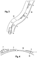
- FIG. 3 schematically shows how several navigation instructions 7 can be adapted to the determined by a plurality of successive curves horizontal course of lying in front of the vehicle F road 10.
- This course 17 can also be calculated by means of lateral acceleration measurements or by measuring the steering angle and vehicle speed, at least for a certain distance. Furthermore, it is possible to estimate the trajectory only from the chosen steering angle of the vehicle steering.
- the information of the existing lane detection system 12 can ensure the correct arrangement and displacement of the navigation instructions 7 within the lane 10.
- Each navigation instruction 7 is rotated according to the determined price course 17 and oriented so that the navigation instruction 7 is always tangent to the tangent t to the predetermined course 17 of the vehicle F.
- the price course 17 (trajectory) follows the course of the lane 10.
- FIG. 4 schematically a corresponding adaptation of the navigation instructions 7 is shown to the front of the vehicle F height profile 18, which may differ from the course of the calculated surface model 19.
- the navigation instructions 7 are folded in the display unit to the rear or to the front, which can be achieved in particular by a graphical extension or compression of the navigation instructions 7 in the vertical direction of the display unit. So that the driver gains the most realistic impression possible, the adaptation of the navigation instructions can take place simultaneously both in the horizontal and in the vertical direction.
Landscapes
- Engineering & Computer Science (AREA)
- Radar, Positioning & Navigation (AREA)
- Remote Sensing (AREA)
- Automation & Control Theory (AREA)
- Physics & Mathematics (AREA)
- General Physics & Mathematics (AREA)
- Multimedia (AREA)
- Navigation (AREA)
- Traffic Control Systems (AREA)
Claims (10)
- Procédé pour afficher au moins une consigne de navigation (7) d'un système de navigation dans un véhicule (F), une portion de l'environnement du véhicule étant enregistrée par une caméra (2) et affichée sous la forme d'une séquence d'images d'environnement (9) au moyen d'une unité d'affichage (4), la consigne de navigation (7) étant également affichée au moyen de l'unité d'affichage (4), caractérisé en ce
que lors du déplacement du véhicule (F), la position de l'au moins une consigne de navigation (7) à l'intérieur de la séquence d'images d'environnement (9) est modifiée en fonction du mouvement de l'environnement qui a lieu par rapport au véhicule (F) et l'au moins une consigne de navigation (7) accompagne (16) le mouvement de la séquence d'images d'environnement (9). - Procédé selon la revendication 1, caractérisé en ce que l'au moins une consigne de navigation (7), dans le cas d'un environnement du véhicule qui se déplace par rapport au véhicule (F), est déplacée (16) uniformément avec l'environnement de véhicule affiché dans la séquence d'images d'environnement (9).
- Procédé selon la revendication 1 ou 2, caractérisé en ce que la taille et/ou la forme de l'au moins une consigne de navigation (7) sont modifiées lors du déplacement du véhicule (F).
- Procédé selon au moins l'une des revendications 1 à 3, caractérisé en ce que lors du déplacement du véhicule (F), la consigne de navigation (7) est approchée d'un bord d'image (15) formé par l'unité d'affichage (4) d'au moins un pixel correspondant à au moins un pixel de la séquence d'images d'environnement (9) affichée, ou en est éloignée.
- Procédé selon au moins l'une des revendications précédentes, caractérisé en ce que lorsque le bord d'image (15) inférieur et/ou un latéral est atteint, une consigne de navigation (7) est affichée de telle sorte qu'elle est déplacée hors de la séquence d'images d'environnement (9) affichée.
- Procédé selon au moins l'une des revendications précédentes, caractérisé en ce que la représentation de l'au moins une consigne de navigation (7) est adaptée au défilement horizontal et/ou vertical de la voie de circulation (10) qui se trouve devant le véhicule (F).
- Procédé selon au moins l'une des revendications précédentes, caractérisé en ce que des consignes de navigation (7) sont affichées de manière répétée le long du défilement de la voie de circulation (10) qui se trouve devant le véhicule (F).
- Procédé selon la revendication 7, caractérisé en ce que l'écart entre deux consignes de navigation (7) dépend de la vitesse du véhicule (14) de telle sorte que l'écart est d'autant plus grand que la vitesse du véhicule (14) est élevée.
- Procédé selon au moins l'une des revendications précédentes, caractérisé en ce qu'en présence d'objets enregistrés qui se déplacent par rapport au véhicule (F) et/ou par rapport à l'environnement, lesquels sont reconnus et affichés dans la séquence d'images d'environnement (9) sous la forme d'image d'objet dans la zone d'une consigne de navigation (7) à afficher de telle sorte qu'il se produit un recoupement entre l'image d'objet et la consigne de navigation (7), la consigne de navigation (7) concernée est soit affichée en semi-transparence superposée à l'image d'objet, soit totalement masquée, jusqu'à ce qu'il n'existe plus de recoupement entre l'image d'objet et la consigne de navigation (7).
- Arrangement (1) pour afficher au moins une consigne de navigation (7) d'un système de navigation pour un véhicule (F), comprenant une caméra (2) qui est disposée de telle sorte qu'elle enregistre une portion de l'environnement du véhicule, une unité de navigation (5) et une unité d'affichage (4), laquelle est conçue de telle sorte qu'elle représente à la fois l'au moins une consigne de navigation (7) ainsi qu'une portion enregistrée de l'environnement du véhicule sous la forme d'une séquence d'images d'environnement (9), caractérisé en ce
que l'unité d'affichage (4) est conçue de telle sorte que lors d'un déplacement du véhicule (F), la position calculée par l'arrangement (1) de l'au moins une consigne de navigation (7) à l'intérieur de la séquence d'images d'environnement (9) est modifiée en fonction du mouvement de l'environnement qui a lieu par rapport au véhicule (F) et accompagne (16) le mouvement de la séquence d'images d'environnement (9).
Applications Claiming Priority (2)
| Application Number | Priority Date | Filing Date | Title |
|---|---|---|---|
| DE102006010478A DE102006010478A1 (de) | 2006-03-07 | 2006-03-07 | Verfahren und Anordnung zur Anzeige von Navigationshinweisen |
| PCT/EP2007/050914 WO2007101755A1 (fr) | 2006-03-07 | 2007-01-30 | Procédé et système pour afficher des indications de navigation |
Publications (2)
| Publication Number | Publication Date |
|---|---|
| EP2002212A1 EP2002212A1 (fr) | 2008-12-17 |
| EP2002212B1 true EP2002212B1 (fr) | 2017-04-26 |
Family
ID=37948825
Family Applications (1)
| Application Number | Title | Priority Date | Filing Date |
|---|---|---|---|
| EP07726265.7A Ceased EP2002212B1 (fr) | 2006-03-07 | 2007-01-30 | Procédé et système pour afficher des indications de navigation |
Country Status (4)
| Country | Link |
|---|---|
| US (1) | US9791288B2 (fr) |
| EP (1) | EP2002212B1 (fr) |
| DE (1) | DE102006010478A1 (fr) |
| WO (1) | WO2007101755A1 (fr) |
Cited By (1)
| Publication number | Priority date | Publication date | Assignee | Title |
|---|---|---|---|---|
| WO2023093952A1 (fr) * | 2021-11-26 | 2023-06-01 | Continental Automotive Technologies GmbH | Procédé, programme informatique et appareil de commande d'un dispositif d'affichage à réalité augmentée |
Families Citing this family (31)
| Publication number | Priority date | Publication date | Assignee | Title |
|---|---|---|---|---|
| WO2006035755A1 (fr) * | 2004-09-28 | 2006-04-06 | National University Corporation Kumamoto University | Méthode pour afficher des informations de navigation de corps mobile et dispositif pour afficher des informations de navigation de corps mobile |
| CN101636636A (zh) * | 2007-03-23 | 2010-01-27 | 三菱电机株式会社 | 导航系统及车道信息显示方法 |
| DE102007053305A1 (de) * | 2007-11-08 | 2009-05-14 | Robert Bosch Gmbh | Verfahren und Vorrichtung zur Ausgabe von optischen Fahrempfehlungen in einem Fahrzeug |
| DE102007054713A1 (de) * | 2007-11-14 | 2009-05-20 | Roericht, Hans, Prof. | Wegweisesystem und Vorrichtung zur Wegweisung |
| JP4994256B2 (ja) * | 2008-01-28 | 2012-08-08 | 株式会社ジオ技術研究所 | 経路案内データベースのデータ構造 |
| DE102008012066A1 (de) * | 2008-02-29 | 2009-09-10 | Navigon Ag | Verfahren zum Betrieb einer Navigationseinrichtung |
| DE102008041295A1 (de) | 2008-08-18 | 2010-02-25 | Robert Bosch Gmbh | Mobiles Navigationsgerät und diesbezügliches Verfahren |
| US20130176328A1 (en) * | 2009-12-25 | 2013-07-11 | Nokia Corporation | Method and apparatus for persistent display of navigation content |
| DE102011006347B4 (de) * | 2011-03-29 | 2023-02-09 | Bayerische Motoren Werke Aktiengesellschaft | Verfahren zur Ausgabe von grafischen Fahrhinweisen |
| DE102011112943B4 (de) | 2011-09-13 | 2020-08-27 | Volkswagen Aktiengesellschaft | Verfahren zum Bereitstellen eines Fahrerassistenzsystems mit automatischer Längsregelung für ein Fahrzeug und Fahrerassistenzsystem dazu |
| DE102011084084A1 (de) * | 2011-10-06 | 2013-04-11 | Robert Bosch Gmbh | Anzeigeverfahren und Anzeigesystem für ein Fahrzeug |
| US8660735B2 (en) | 2011-12-14 | 2014-02-25 | General Motors Llc | Method of providing information to a vehicle |
| DE102012001951A1 (de) * | 2012-02-02 | 2013-08-08 | Daimler Ag | Anzeigevorrichtung für ein Fahrzeug und Verfahren zum Betreiben einer Anzeigevorrichtung |
| DE102012001950A1 (de) * | 2012-02-02 | 2013-08-08 | Daimler Ag | Verfahren zum Betreiben einer Kameraanordnung für ein Fahrzeug und Kameraanordnung |
| WO2014095068A1 (fr) * | 2012-12-21 | 2014-06-26 | Harman Becker Automotive Systems Gmbh | Système d'infodivertissement |
| US9251627B2 (en) * | 2013-03-05 | 2016-02-02 | Sears Brands, L.L.C. | Removable dashboard instrument system |
| DE102013011827A1 (de) | 2013-07-15 | 2015-01-15 | Audi Ag | Verfahren zum Betrieb einer Navigationseinrichtung, Navigationseinrichtung und Kraftfahrzeug |
| DE102013019144B4 (de) * | 2013-11-15 | 2020-12-31 | Audi Ag | Head-up-Display für ein Fahrzeug und Verfahren zum Bereitstellen eines elektronischen Bildsignals für ein Head-up-Display |
| WO2016087906A1 (fr) * | 2014-12-05 | 2016-06-09 | Audi Ag | Dispositif d'affichage pour véhicule et procédé pour assister un conducteur devéhicule, en particulier un véhicule pour passagers |
| DE102016218006A1 (de) | 2016-09-20 | 2018-03-22 | Volkswagen Aktiengesellschaft | Verfahren zur Darstellung eines Bildobjekts in einem Fahrzeug auf einer fahrzeugintern und einer fahrzeugextern wahrgenommenen Anzeige |
| KR102695518B1 (ko) * | 2017-01-26 | 2024-08-14 | 삼성전자주식회사 | 차량 경로 가이드 방법 및 장치 |
| DE102017217747A1 (de) | 2017-10-05 | 2019-04-11 | Volkswagen Aktiengesellschaft | Verfahren zum Betrieb eines Navigationssystems |
| DE102017220268B4 (de) * | 2017-11-14 | 2024-03-21 | Volkswagen Aktiengesellschaft | Erkennung und Visualisierung von Systemunsicherheit bei der Darstellung augmentierter Bildinhalte in Head-Up-Displays |
| US11520335B2 (en) * | 2018-04-12 | 2022-12-06 | Baidu Usa Llc | Determining driving paths for autonomous driving vehicles based on map data |
| US10755571B1 (en) * | 2019-03-01 | 2020-08-25 | Amazon Technologies, Inc. | Identifying parking location using single camera reverse projection |
| DE102020201242A1 (de) | 2020-01-31 | 2021-08-05 | Volkswagen Aktiengesellschaft | Verfahren zum Anzeigen einer Hinweisinformation als Hinweis für ein nachfolgendes Abbiegen eines Fahrzeugs an einer Abbiegestelle auf einer Anzeigeeinheit des Fahrzeugs kontaktanalog, sowie Anzeigevorrichtung und Fahrzeug |
| DE102020202964A1 (de) * | 2020-03-09 | 2021-09-09 | Continental Automotive Gmbh | Die Erfindung betrifft ein Verfahren zur Erhöhung der Sicherheit von Fahrfunktionen. |
| DE102020211301A1 (de) * | 2020-09-09 | 2022-03-10 | Volkswagen Aktiengesellschaft | Verfahren zur Darstellung eines virtuellen Elements |
| KR20230111629A (ko) * | 2022-01-17 | 2023-07-26 | 현대자동차주식회사 | 차량 내부의 디스플레이 장치 및 그 제어방법 |
| DE102022133405A1 (de) * | 2022-12-15 | 2024-06-20 | Valeo Schalter Und Sensoren Gmbh | Verfahren zum bereitstellen eines anzeigbaren pfads |
| JP2025174040A (ja) * | 2024-05-16 | 2025-11-28 | パナソニックオートモーティブシステムズ株式会社 | 表示装置、表示方法、及び、プログラム |
Family Cites Families (16)
| Publication number | Priority date | Publication date | Assignee | Title |
|---|---|---|---|---|
| JPH09304101A (ja) | 1996-05-14 | 1997-11-28 | Matsushita Electric Ind Co Ltd | ナビゲーション装置 |
| JP3708221B2 (ja) | 1996-06-05 | 2005-10-19 | 松下電器産業株式会社 | 走行位置表示装置 |
| JPH1123305A (ja) | 1997-07-03 | 1999-01-29 | Toyota Motor Corp | 車両用走行案内装置 |
| US6285317B1 (en) | 1998-05-01 | 2001-09-04 | Lucent Technologies Inc. | Navigation system with three-dimensional display |
| JP3494143B2 (ja) * | 1999-11-18 | 2004-02-03 | トヨタ自動車株式会社 | 経路案内情報提供システムおよび経路案内情報提供方法 |
| JP2001241962A (ja) * | 2000-02-25 | 2001-09-07 | Matsushita Electric Ind Co Ltd | ナビゲーション装置 |
| DE10138719A1 (de) * | 2001-08-07 | 2003-03-06 | Siemens Ag | Verfahren und Vorrichtung zur Darstellung von Fahrhinweisen, insbesondere in Auto-Navigationssystemen |
| DE10203413C2 (de) | 2002-01-28 | 2003-11-27 | Daimler Chrysler Ag | Automobiles Infrarot-Nachtsichtgerät |
| DE10253510A1 (de) | 2002-11-16 | 2004-05-27 | Robert Bosch Gmbh | Vorrichtung und Verfahren zur Verbesserung der Sicht in einem Kraftfahrzeug |
| JP2004257979A (ja) | 2003-02-27 | 2004-09-16 | Sanyo Electric Co Ltd | ナビゲーション装置 |
| DE10344120A1 (de) | 2003-09-24 | 2005-04-21 | Daimler Chrysler Ag | Vorrichtung und Verfahren zur Darstellung von Fahrhinweisen |
| MX2007015348A (es) * | 2005-06-06 | 2008-02-15 | Tomtom Int Bv | Dispositivo de navegacion con informacion de camara. |
| JP2007121001A (ja) * | 2005-10-26 | 2007-05-17 | Matsushita Electric Ind Co Ltd | ナビゲーション装置 |
| EP2015023A4 (fr) * | 2006-04-28 | 2012-09-12 | Panasonic Corp | Dispositif et procede de navigation |
| TW200834040A (en) * | 2007-02-02 | 2008-08-16 | Mitac Int Corp | Dioramic navigation apparatus |
| US9459113B2 (en) * | 2008-11-21 | 2016-10-04 | GM Global Technology Operations LLC | Visual guidance for vehicle navigation system |
-
2006
- 2006-03-07 DE DE102006010478A patent/DE102006010478A1/de not_active Withdrawn
-
2007
- 2007-01-30 US US12/281,557 patent/US9791288B2/en not_active Expired - Fee Related
- 2007-01-30 WO PCT/EP2007/050914 patent/WO2007101755A1/fr not_active Ceased
- 2007-01-30 EP EP07726265.7A patent/EP2002212B1/fr not_active Ceased
Cited By (1)
| Publication number | Priority date | Publication date | Assignee | Title |
|---|---|---|---|---|
| WO2023093952A1 (fr) * | 2021-11-26 | 2023-06-01 | Continental Automotive Technologies GmbH | Procédé, programme informatique et appareil de commande d'un dispositif d'affichage à réalité augmentée |
Also Published As
| Publication number | Publication date |
|---|---|
| WO2007101755A1 (fr) | 2007-09-13 |
| DE102006010478A1 (de) | 2007-09-13 |
| US9791288B2 (en) | 2017-10-17 |
| EP2002212A1 (fr) | 2008-12-17 |
| US20090222203A1 (en) | 2009-09-03 |
Similar Documents
| Publication | Publication Date | Title |
|---|---|---|
| EP2002212A1 (fr) | Procédé et système pour afficher des indications de navigation | |
| EP1994366B1 (fr) | Procédé et système pour afficher des indications de navigation | |
| DE102004012604B4 (de) | Verfahren zum Betrieb eines Darstellungssystems in einem Fahrzeug zum Anfahren eines Parkplatzes | |
| EP1415128B1 (fr) | Procede et dispositif pour representer des indications de conduite, en particulier dans des systemes de navigation pour vehicules automobiles | |
| EP2289058B1 (fr) | Procédé de sortie combinée d'une image et d'une information locale, et véhicule à moteur associé | |
| EP2156238B1 (fr) | Procédé pour indiquer un tracé de chaussée et dispositif de commande | |
| EP2998937B1 (fr) | Dispositif d'affichage pour vehicules, notamment vehicules utilitaires | |
| DE102015116043A1 (de) | Sichtlinien-Führungsvorrichtung für Fahrzeuge | |
| EP3762684A1 (fr) | Incrustation d'informations additionnelles sur une unité d'affichage | |
| DE112018004521T5 (de) | Anzeigevorrichtung eines überlagerten Bildes und Computerprogramm | |
| EP1931538A1 (fr) | Dispositif de vision nocturne pour automobile | |
| DE112016002268T5 (de) | Bildverarbeitungsvorrichtung, elektronisches spiegelsystem und bildverarbeitungsverfahren | |
| WO2019105679A1 (fr) | Procédé d'affichage du déroulement d'une trajectoire devant un véhicule ou un objet pourvu d'une unité d'affichage, dispositif de mise en œuvre du procédé | |
| EP3978294A1 (fr) | Fonctionnement d'un dispositif d'affichage tête haute en cas d'objets affichables positionnés en dehors d'un champ de vision | |
| DE102010003851A1 (de) | Verfahren und Informationssystem zum Markieren eines Zielorts für ein Fahrzeug | |
| DE102008006309A1 (de) | Verfahren und Vorrichtung zur Fahrerunterstützung beim Rangieren eines Fahrzeuges oder Fahrzeuggespanns | |
| EP3288797B1 (fr) | Procédé et système pour commander un système de remplacement de rétroviseur extérieur d'un véhicule dans une zone dans laquelle deux trajectoires se croisent et système de remplacement de rétroviseur extérieur équipé d'un tel système | |
| EP1832848B1 (fr) | Procédé et dispositif destinés à l'affichage d'une section de carte numérique | |
| EP3978295B1 (fr) | Fonction d'aide visuelle se basant sur la voie de circulation d'un dispositif d'affichage tête haute pour véhicule automobile | |
| DE102022209182A1 (de) | Anzeigeverfahren zur Darstellung eines virtuellen Umgebungsmodells, Computerprogramm, Rechenvorrichtung und Fahrzeug | |
| DE102014016566A1 (de) | Kraftfahrzeug mit Kamera | |
| EP2943750B1 (fr) | Dispositif de navigation pour un véhicule et procédé de génération d'un signal d'affichage pour un tel dispositif de navigation | |
| DE102023200200A1 (de) | Verfahren zum Betreiben eines Rückspiegelsystems sowie Rückspiegelsystem | |
| DE102025107004A1 (de) | Verfahren zur Visualisierung eines vorausliegenden Streckenabschnitts in einem Ego-Fahrzeug | |
| DE102023213128A1 (de) | Computerimplementiertes Verfahren zur Anzeige einer Umgebung eines Fahrzeugs, Computerprogramm, Rechenvorrichtung und Fahrzeug |
Legal Events
| Date | Code | Title | Description |
|---|---|---|---|
| PUAI | Public reference made under article 153(3) epc to a published international application that has entered the european phase |
Free format text: ORIGINAL CODE: 0009012 |
|
| 17P | Request for examination filed |
Effective date: 20081007 |
|
| AK | Designated contracting states |
Kind code of ref document: A1 Designated state(s): DE FR GB IT |
|
| RIN1 | Information on inventor provided before grant (corrected) |
Inventor name: MUELLER-FRAHM, MARIO |
|
| DAX | Request for extension of the european patent (deleted) | ||
| RBV | Designated contracting states (corrected) |
Designated state(s): DE FR GB IT |
|
| 17Q | First examination report despatched |
Effective date: 20110923 |
|
| GRAP | Despatch of communication of intention to grant a patent |
Free format text: ORIGINAL CODE: EPIDOSNIGR1 |
|
| INTG | Intention to grant announced |
Effective date: 20161121 |
|
| GRAS | Grant fee paid |
Free format text: ORIGINAL CODE: EPIDOSNIGR3 |
|
| GRAA | (expected) grant |
Free format text: ORIGINAL CODE: 0009210 |
|
| AK | Designated contracting states |
Kind code of ref document: B1 Designated state(s): DE FR GB IT |
|
| REG | Reference to a national code |
Ref country code: GB Ref legal event code: FG4D Free format text: NOT ENGLISH |
|
| REG | Reference to a national code |
Ref country code: DE Ref legal event code: R096 Ref document number: 502007015604 Country of ref document: DE |
|
| REG | Reference to a national code |
Ref country code: FR Ref legal event code: PLFP Year of fee payment: 12 |
|
| REG | Reference to a national code |
Ref country code: DE Ref legal event code: R097 Ref document number: 502007015604 Country of ref document: DE |
|
| PLBE | No opposition filed within time limit |
Free format text: ORIGINAL CODE: 0009261 |
|
| STAA | Information on the status of an ep patent application or granted ep patent |
Free format text: STATUS: NO OPPOSITION FILED WITHIN TIME LIMIT |
|
| 26N | No opposition filed |
Effective date: 20180129 |
|
| PGFP | Annual fee paid to national office [announced via postgrant information from national office to epo] |
Ref country code: GB Payment date: 20190124 Year of fee payment: 13 Ref country code: IT Payment date: 20190121 Year of fee payment: 13 Ref country code: DE Payment date: 20190326 Year of fee payment: 13 Ref country code: FR Payment date: 20190123 Year of fee payment: 13 |
|
| REG | Reference to a national code |
Ref country code: DE Ref legal event code: R119 Ref document number: 502007015604 Country of ref document: DE |
|
| GBPC | Gb: european patent ceased through non-payment of renewal fee |
Effective date: 20200130 |
|
| PG25 | Lapsed in a contracting state [announced via postgrant information from national office to epo] |
Ref country code: DE Free format text: LAPSE BECAUSE OF NON-PAYMENT OF DUE FEES Effective date: 20200801 Ref country code: FR Free format text: LAPSE BECAUSE OF NON-PAYMENT OF DUE FEES Effective date: 20200131 Ref country code: GB Free format text: LAPSE BECAUSE OF NON-PAYMENT OF DUE FEES Effective date: 20200130 |
|
| PG25 | Lapsed in a contracting state [announced via postgrant information from national office to epo] |
Ref country code: IT Free format text: LAPSE BECAUSE OF NON-PAYMENT OF DUE FEES Effective date: 20200130 |