EP2002247B1 - Dispositif constitue d'une chambre de mesure et d'un resonateur integre dans la chambre de mesure au moyen d'une fermeture rapide et destine a la detection de liquide - Google Patents
Dispositif constitue d'une chambre de mesure et d'un resonateur integre dans la chambre de mesure au moyen d'une fermeture rapide et destine a la detection de liquide Download PDFInfo
- Publication number
- EP2002247B1 EP2002247B1 EP07723675.0A EP07723675A EP2002247B1 EP 2002247 B1 EP2002247 B1 EP 2002247B1 EP 07723675 A EP07723675 A EP 07723675A EP 2002247 B1 EP2002247 B1 EP 2002247B1
- Authority
- EP
- European Patent Office
- Prior art keywords
- resonator
- ring
- contact
- sealing
- measurement chamber
- Prior art date
- Legal status (The legal status is an assumption and is not a legal conclusion. Google has not performed a legal analysis and makes no representation as to the accuracy of the status listed.)
- Not-in-force
Links
Images




Classifications
-
- G—PHYSICS
- G01—MEASURING; TESTING
- G01N—INVESTIGATING OR ANALYSING MATERIALS BY DETERMINING THEIR CHEMICAL OR PHYSICAL PROPERTIES
- G01N29/00—Investigating or analysing materials by the use of ultrasonic, sonic or infrasonic waves; Visualisation of the interior of objects by transmitting ultrasonic or sonic waves through the object
- G01N29/02—Analysing fluids
- G01N29/036—Analysing fluids by measuring frequency or resonance of acoustic waves
-
- G—PHYSICS
- G01—MEASURING; TESTING
- G01N—INVESTIGATING OR ANALYSING MATERIALS BY DETERMINING THEIR CHEMICAL OR PHYSICAL PROPERTIES
- G01N29/00—Investigating or analysing materials by the use of ultrasonic, sonic or infrasonic waves; Visualisation of the interior of objects by transmitting ultrasonic or sonic waves through the object
- G01N29/02—Analysing fluids
- G01N29/022—Fluid sensors based on microsensors, e.g. quartz crystal-microbalance [QCM], surface acoustic wave [SAW] devices, tuning forks, cantilevers, flexural plate wave [FPW] devices
-
- G—PHYSICS
- G01—MEASURING; TESTING
- G01N—INVESTIGATING OR ANALYSING MATERIALS BY DETERMINING THEIR CHEMICAL OR PHYSICAL PROPERTIES
- G01N29/00—Investigating or analysing materials by the use of ultrasonic, sonic or infrasonic waves; Visualisation of the interior of objects by transmitting ultrasonic or sonic waves through the object
- G01N29/22—Details, e.g. general constructional or apparatus details
- G01N29/222—Constructional or flow details for analysing fluids
-
- G—PHYSICS
- G01—MEASURING; TESTING
- G01N—INVESTIGATING OR ANALYSING MATERIALS BY DETERMINING THEIR CHEMICAL OR PHYSICAL PROPERTIES
- G01N2291/00—Indexing codes associated with group G01N29/00
- G01N2291/01—Indexing codes associated with the measuring variable
- G01N2291/018—Impedance
-
- G—PHYSICS
- G01—MEASURING; TESTING
- G01N—INVESTIGATING OR ANALYSING MATERIALS BY DETERMINING THEIR CHEMICAL OR PHYSICAL PROPERTIES
- G01N2291/00—Indexing codes associated with group G01N29/00
- G01N2291/02—Indexing codes associated with the analysed material
- G01N2291/022—Liquids
- G01N2291/0224—Mixtures of three or more liquids
-
- G—PHYSICS
- G01—MEASURING; TESTING
- G01N—INVESTIGATING OR ANALYSING MATERIALS BY DETERMINING THEIR CHEMICAL OR PHYSICAL PROPERTIES
- G01N2291/00—Indexing codes associated with group G01N29/00
- G01N2291/02—Indexing codes associated with the analysed material
- G01N2291/025—Change of phase or condition
- G01N2291/0255—(Bio)chemical reactions, e.g. on biosensors
-
- G—PHYSICS
- G01—MEASURING; TESTING
- G01N—INVESTIGATING OR ANALYSING MATERIALS BY DETERMINING THEIR CHEMICAL OR PHYSICAL PROPERTIES
- G01N2291/00—Indexing codes associated with group G01N29/00
- G01N2291/02—Indexing codes associated with the analysed material
- G01N2291/025—Change of phase or condition
- G01N2291/0256—Adsorption, desorption, surface mass change, e.g. on biosensors
-
- G—PHYSICS
- G01—MEASURING; TESTING
- G01N—INVESTIGATING OR ANALYSING MATERIALS BY DETERMINING THEIR CHEMICAL OR PHYSICAL PROPERTIES
- G01N2291/00—Indexing codes associated with group G01N29/00
- G01N2291/04—Wave modes and trajectories
- G01N2291/042—Wave modes
- G01N2291/0422—Shear waves, transverse waves, horizontally polarised waves
Definitions
- the invention relates to a device consisting of a measuring chamber and a resonator according to the preamble of claim 1.
- a sensor for detecting a substance in a liquid wherein the sensor is designed as a resonator, which is integrated by means of a sealing device in a measuring chamber.
- This resonator is in contact with the liquid to be examined at one of its end faces, and mass accumulation by a substance to be detected or measured in its concentration on this surface leads to a change in the resonant frequency or / and the oscillation amplitude of the resonator.
- a change of these two parameters can also be caused by different fluid properties.
- the invention therefore relates in particular to the field of piezoelectric oscillatory quartz sensors which serve to detect or to measure the concentration of biological, chemical or biochemical substances and of microorganisms in liquids or to determine the liquid properties.
- quartz oscillator holders are usually used, in which the quartz oscillator is contacted and fixed by two electrical supply wires with bow-shaped ends.
- the feed wires penetrate an electrically insulated base plate to which an electromagnetic shielding can be slipped.
- Another method for fixing and contacting can be found in the DE 3446612 or the DE 19926944 ,
- the sealing of the upper end face is effected in the known support systems for piezoelectric quartz oscillators either by a seal, usually from a silicone ring which presses on the upper end face of the quartz crystal, or by gluing the quartz crystal into a holder realized ( DE 197 34 706 A1 ).
- the electrical contact via contact springs, bonding wires, conductive rubber or conductive adhesive body ( DE 401 13 665 ).
- the quartz crystal directly into the measuring chamber, which is made of an injection molded part, integrated firmly over adhesive.
- the electrical contacting is mechanically stress-free via bonding wires.
- This measuring chamber which is also referred to as "flow cell”, can be installed and removed in a measuring arrangement without influencing the quartz crystal parameters.
- the quartz crystal surface is often easily accessible for a biological coating and also an optical accessibility of the quartz crystal surface in the built-in measuring chamber state is in principle possible, but the quartz crystal is by the sealing principle and installation mechanically clamped differently. This has the consequence that a short-term removal and installation during a measurement and thus the characterization of the quartz crystal surface by a light microscope, atomic force microscope, etc. is not possible.
- Another disadvantage of this method is the not exactly defined wetting surface of the upper quartz crystal surface. If the contact pressure of the seal is too low, the wetting liquid escapes or the resulting short circuit of the two quartz electrodes occurs.
- a very crucial disadvantage of this mounting principle with respect to the analysis of liquids that z. B. include "heavy" particles or human cells is the principle conditional flow barrier by the large-sized seal or the large-sized sealing ring.
- a tangential flow introduction is therefore only conditionally possible and the removal of the analyte after a measurement is only possible with very high flow rates or not at all.
- the high flow rates in turn affect the vibrational behavior of the quartz crystal and require a very high density even at high pressures.
- WO 02/12873 A discloses a quartz crystal sensor as a mass sensor system which measures minute changes on the surface of a piezoelectric crystal, wherein two housing parts form a measuring chamber in which a resonator is arranged, which is held and sealed only by a thin sealing ring on its outer periphery the sealing ring rests against an upper sealing ring and rests on a lower retaining ring.
- WO 2005/066621 discloses a structure of a surface acoustic wave sensor for measuring substance concentrations and substances in liquids, wherein the sensor is flowed through by the liquid and having a circuit layer and an acoustic wave sensor, wherein the acoustic wave sensor is arranged by means of a conductive elastomeric seal sealingly on the circuit layer.
- the invention is therefore based on the object to reduce the mechanical stress arising during the installation of a resonator and to form an improved mechanical insulation of the housing.
- An essential feature of the invention is that the resonator is held and sealed only on its outer periphery by a thin elastomeric ring and that at a radial distance from the outer diameter of the resonator, the film ring on the one hand sealingly abuts an upper sealing ring of the measuring chamber and on the other hand rests on a retaining ring.
- the essence of the invention lies in the fact that the resonator is held and sealed only on a very thin elastomeric ring on its outer periphery and that at the radial distance from this holder on the resonator outside the elastomeric ring is received between two mutually associated surfaces, one of these Surfaces is designed as a sealing ring.
- this elastomeric ring consists only of a film ring, which has the thickness of a conventional film, namely in the range of 50 to 300 microns and from a conventional film material, such. As PVC or the like. It is preferred in this case if this film ring is as thin as possible and coated on one side with an adhesive layer, because then the holder between this ring and the resonator via an adhesive layer on the outer circumference of the resonator.
- disc-shaped resonator refers only to a preferred embodiment of the invention. It is of course also claimed essential to the invention that the resonator has different outlines, z. B. it may be rectangular, square, hexagonal, designed as a parallelogram and the like. The use of the term “disc-shaped” resonator is thus intended only to simplify the explanation of a preferred embodiment.
- the seal arrangement which is described in more detail below, must be adapted to the current outline of the resonator.
- the sealing arrangement only extends to a certain extent in the outer region of the resonator, where it is not its active, oscillating surface, and that thereby the resonator is kept completely pressure-free.
- the sealing of the resonator takes place free of stress only at the outside oscillating with very small amplitude and that the second sealing surface is moved radially outward from the outer periphery of the resonator in the region of the measuring chamber, so as to the resonator as possible little vibration damped and to keep it tension-free below or in said elastomeric ring (foil ring).
- ring foil ring foil
- it may also be provided to provide the foil by sputtering or coating the resonator itself.
- the surface of the resonator is vapor-deposited with a gold coating and this gold coating is pulled out radially outward over the outer circumference of the resonator and continued, so as to form the elastic ring.
- This can also be done by a plastic coating or other materials.
- the ring is mounted by sputtering directly on the surface of the resonator, so that an absolutely flat transition - without the interposition of any film stages - forms the measuring chamber and that the measuring chamber is completely flat and free edge formed. There is therefore not even the smallest step transition, as is the case later to be described, where the film ring, for example, has a thickness of 100 microns and partially overlaps with its disc-shaped inner circumference of the outer circumference of the resonator and holds there.
- the fixture should have only minor flow barriers. Otherwise, the "heavy" particles or cells can settle due to the barriers and thus can no longer be removed from the measuring chamber.
- the holder In the case of a biological coating of the end face operated in liquid phase, the holder should be designed such that a tangential flow introduction is possible, so that the biological layer is not “washed off” and at the same time variants of the flow parameters have less influence.
- quartz crystal surface after the removal of the integrated into the crystal quartz mount quartz crystal from the measuring chamber to provide the quartz crystal surface with one or more biological layers.
- This accessibility together with the requirement that rapid removal and installation into the measuring chamber of the quartz crystal built-in oscillator crystal crystal without influencing the quartz crystal parameters is feasible, the possibility of characterizing the quartz crystal surface during a measurement, z. B. with a light microscope, an atomic force microscope, etc.
- the quartz crystal holder is intended to further improve the handling of the provided in the case of biosensing with a biological layer quartz crystals outside the measuring chamber.
- the direct handling of the quartz crystal with tweezers can very quickly lead to cracking of the brittle quartz crystal. Touching the quartz crystal surface with tweezers also destroys the biological layer.
- the edge to be wiped is the one to be wiped Oscillating quartz surface applied with an adhesive coated film ring having a larger outer diameter than the quartz crystal, and thereby sealed the upper end face.
- the inner diameter of the film ring is chosen so that only the oscillating with a very small amplitude outer region of the upper end surface of the quartz crystal is covered with the film.
- the projecting beyond the quartz crystal part of the film ring is glued to a plastic ring (retaining ring).
- the curing of the adhesive takes place z. B. by briefly heating the film, z. B. by a soldering tip or hot plate.
- the electrical contacting takes place at the lower end face of the quartz crystal, by placing the quartz crystal built into the quartz crystal mount on a second plastic ring, the so-called Mulltechniksring, on the surface of which two metallic electrodes are applied.
- Thisêt istsring has a smaller outer diameter than the inner diameter of the support ring and a smaller by the quartz crystal thickness height.
- the contact pads are positioned on the lower end face just above the electrodes of the contacting ring.
- the quartz crystal is defined by the elastic properties of the film pressed exactly defined on the contacting ring and achieved a very good electrical contact without mechanically clamping the quartz crystal.
- the inner diameter of the contacting ring is selected so that only the edge regions of the lower end face, which oscillate with a very small amplitude, rest and the shearing vibration of the quartz crystal is therefore only very slightly damped by the contacting ring.
- the measuring chamber With a corresponding design of the measuring chamber belonging to the invention, it is possible by the support system described, the measuring chamber above the quartz crystal by a quick release, z. B. a bayonet lock, liquid-tight press, without crucial to clamp the quartz crystal mechanically or to mechanically clamp differently after installation and removal. Since the film has a very small thickness ⁇ 0.1 mm and thus does not represent a large flow barrier, the flow can be introduced tangentially with appropriate geometry of the measuring chamber. It is possible by this mounting system to place the liquid supply lines outside the optical window, which allows optical observation of the quartz crystal surface during a measurement or injection of a liquid, etc. with simultaneous tangential flow introduction. Moreover, this arrangement makes it possible to set the height of the optically permeable stamp and thus the measuring chamber volume exactly to different values via an adjusting screw. A thermostating z. B. by a Peltier system from below, without hindering the optical access.
- FIG. 1 is schematic and increases the lower part of a measuring chamber 36 after the FIGS. 7 to 11 and a measuring device which is sealingly connected to the lower part of the measuring chamber 36.
- a disk-shaped resonator 1 (which, for example, has the size of a 1-cent piece) is mounted as a disk-shaped oscillating body in a holder according to the invention.
- the resonator 1 rests with its contact surfaces 2, 3 with a precisely defined contact pressure on the contact surfaces 4, 5 of a contacting ring 6 arranged opposite thereto.
- the contacting ring 6 is preferably formed of an electrically insulating material, and the contact surfaces 4, 5 are formed only as Leitsilberbahnen or the like.
- the power supply lines 7 of these contact surfaces 4, 5 are connected to the output of an oscillator circuit, wherein the electrical oscillation frequency of the oscillator circuit of the mechanical oscillation of the resonator is tracked.
- the resonator 1 is thus completely free over a cavity 8, which is formed in the interior of the disk-shaped Kunststofftechniksringes 6.
- an adhesive film is attached, which is formed in the embodiment shown as a film ring 11.
- the film ring 11 is in conjunction with its adhesive coating in greatly exaggerated proportions in FIG. 1 and the following figures to better explain the context.
- the film thickness is in the range of 50 to 200 ⁇ m.
- the core of the invention lies in the lowest possible damping and tension-free storage of the resonator 1 in the attachment area between its outer diameter 9 and the associated inner diameter of the film ring eleventh
- the inner diameter 13 of the film ring engages over the outer diameter of the resonator 1 only by a small amount of z. B. 2/10 mm, so that it is ensured that oscillating portions of the resonator 1 are not included in this holder.
- the film ring 11 is held at a radial distance outwardly from the outer diameter of the resonator 1 in two opposing surfaces, wherein one of the surfaces serves as a sealing point.
- the sealing point is formed by a ring encircling sealing ring 17 which is arranged on the underside of the measuring chamber 36, while the opposite part is formed by a retaining ring 10, which consists of a dimensionally stable material, such as. As polypropylene, PPE or the like exists.
- This retaining ring 10 forms the counter surface for the upper, opposite sealing ring 17 and its formation can be varied within wide limits. He can even be designed as a metal ring.
- FIG. 2 shows on an enlarged scale the special sealing effect of the film ring 11 in conjunction with the resonator first
- the contact pressure or the sealing pressure is thus passed in the direction of arrow 21 down over the only slightly deforming film ring 11 and introduced to the opposite fixed contact surface or counter surface, which is given by the support ring 10 and the only direction of arrow 22 in FIG. 2 is shown symbolically.
- the seal therefore takes place not only in the region of the upper edge 15, but in the region of the adhesive surface 12, namely in the overlapping region, where the film ring 11 with its inner diameter 13 engages over the outer diameter of the resonator 1 and holds there
- the seal is made by the bonding of the film with the quartz crystal.
- the invention is not limited to this Klebehalterung.
- a firmer film is used for the holder, which create the seal by the mere pressure from the top of the resonator.
- the inner diameter 16 of the upper sealing ring 17 does not act on the resonator 1 - as it disadvantageously belongs to the prior art - but that it rests on the outer film portion of the film ring 11.
- the sealing surface between the upper sealing ring 17 is thus produced in the region of the sealing surface 19 and in the region of the lower retaining ring 10 in the region of the bearing surface 20. These two bearing surfaces are always loaded independently of the sealing pressure, and this contact pressure is not-as described above-introduced to the resonator 1.
- guided channels 34, 35 are present in the outer regions, where, for example, to investigating substance flows via the channel 34 in the direction of arrow 28 into the inflow space 32, which has the smallest possible volume and which is connected in a fluid-conducting manner to the actual measuring space 33.
- the examined substrate flows again in the direction of arrow 37 from the Ausström syndromem shown there into the channel 35 of the measuring chamber and is discharged there.
- the upper boundary of the measuring space 33 is formed by a vertically adjustable optical window 29, so that the type and appearance of the measuring surface 25 can be controlled at any time from above through the optical window 29.
- the height adjustment is in this case in the direction of arrow 30 in FIG. 1 symbolized.
- the end face 31 of the optical window 29 thus forms a height-adjustable distance to the measuring surface 25 of the resonator 1.
- the invention is not limited to an oblique insertion through obliquely set channels 34, 35 of substances in the measuring space 33. It can also be provided that the channels 34, 35 are guided exactly parallel to the measuring surface 25 of the resonator 1 in the measuring chamber 36.
- the advantage of the thin film ring 11 used is that even a tangential introduction is possible at all, because there are no disturbing projections in the tangential direction over the measuring surface 25 of the resonator 1.
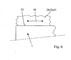
- the measuring surface 25 of the resonator 1 with a protein coating 24 (eg., Protein A) provided. It is a thin, streaky order.
- IgG antibodies 26 are then immobilized on the protein coating 24.
- the erythrocytes 61 are bound to the IgG antibodies26. bound.
- the resonator 1 is excited with an alternating electrical voltage. It forms inside the resonator, a standing transverse wave, which propagates in the vertical direction (arrow 39) upwards into the substance 24 into it.
- the two end faces 25 of the resonator therefore carry out a shearing oscillation, which is represented schematically by the arrow directions 38.
- the mechanical resonance frequency or / and the oscillation amplitude of the resonator 1 changes.
- the frequency of the electrical AC voltage is tracked by the oscillator circuit supplying the resonator 1 to the mechanical resonance frequency.
- the frequency change of the electrical AC voltage can be detected by a frequency counter and serves as a measure of the change in the mass loading of the measuring surface 25 of the resonator first
- the attenuation caused by the deposited layer can be measured.
- FIGS. 7 to 11 the structure of a measuring chamber 36 is shown in more detail.
- the measuring chamber 36 consists essentially of a metal or plastic housing 42, which defines a central, central recess into which the viewing punch 41 made of a transparent plastic material (or made of glass) is height adjustable.
- the housing 42 is screwed by means of any quick-release (z., A bayonet lock) on a lower part, not shown, which, for example, with reference numeral 54 as a holder in FIG. 12 is shown.
- any quick-release z., A bayonet lock
- the bayonet flanges 43 thus engage in associated receiving flanges on the holder 54 FIG. 12 and are set there.
- the aforementioned sealing ring 17 is arranged, which produces the seal to the measuring device.
- the housing is formed substantially in two stages and consists of an upper part with a smaller diameter, the material integrally merges into a housing lower part 44 of larger diameter.
- an adjusting wheel 46 is provided, which cooperates with a thread not shown on the housing 42.
- the sighting punch 41 forms on its upper end face a display window 48, through which the surface of the resonator 1 can be observed.
- the adjusting wheel 46 has a series of ring-running, a mutual distance from each other engaging display windows 48, so that the rotation of the Justierrades 46 can be seen with an opposite measuring mark adjustable and is determined by means of a fixing screw 52.
- FIG. 12 a complete sensor unit 53 is shown, wherein two adjacent measuring chambers 36 are present.
- One measuring chamber 36 is fully populated and above the location of the other measuring chamber only one holder 55 for a CCD camera is arranged, while the measuring chamber located there is itself taken.
- These two measuring chambers 36, 36 ' can be operated in series or in parallel with each other.
- analyte vessels 56 are arranged in the sensor unit 53, to which buffer vessels 57 are assigned.
- the corresponding examination liquid is thus taken from the analyte vessels 56 and optionally with a preceding or trailing
- Buffer liquid displaced from the buffer vessels 57 in the pipeline system Buffer liquid displaced from the buffer vessels 57 in the pipeline system.
- the terminal 58 is the output of the oscillator circuit arranged in the sensor unit 53, and the terminal 59 serves to connect an impedance measuring device.
- connection 60 which is designed as a multi-channel connection
- various electrical signals and, incidentally, also the power supply are supplied.
- an absolutely temperature-stable environment is produced with the aid of Peltier elements, so that the entire sensor unit 53 together with the measuring chambers 36 arranged there is stably controlled to a relatively low temperature range of, for example, ⁇ 0.06 ° C.
- a thermostated water bath is arranged below the sensor unit 53, through which the analyte liquids are passed before they are injected into the measuring chambers 36.
Landscapes
- Physics & Mathematics (AREA)
- Acoustics & Sound (AREA)
- Health & Medical Sciences (AREA)
- Life Sciences & Earth Sciences (AREA)
- Chemical & Material Sciences (AREA)
- Analytical Chemistry (AREA)
- Biochemistry (AREA)
- General Health & Medical Sciences (AREA)
- General Physics & Mathematics (AREA)
- Immunology (AREA)
- Pathology (AREA)
- Apparatus Associated With Microorganisms And Enzymes (AREA)
- Piezo-Electric Or Mechanical Vibrators, Or Delay Or Filter Circuits (AREA)
- Investigating Or Analysing Biological Materials (AREA)
Claims (15)
- Dispositif constitué d'une chambre de mesure et d'un résonateur (1) intégré dans la chambre de mesure au moyen d'une fermeture rapide pour la détection de liquides et la détection/mesure de la concentration de substances ou d'autres microorganismes dans les liquides présentant les pièces suivantes:a. Un boîtier (42) consistant de deux éléments pouvant être fixées;b. Un résonateur (1) en contact avec le fluide devant être analysé et réagissant à une addition en masse de la matière, substance, particule ou microorganisme à analyser en modifiant sa fréquence de résonance ou son amortissement ;c. Un dispositif d'étanchéité avec bague d'étanchéité (17) disposé entre le boîtier (42) et le résonateur (1) dont lad. surface d'appui est en contact avec d'autres pièces (36, 11, 11") du dispositif, caractérisé en ce quee. le résonateur (1) est entouré et étanchéifié uniquement sur son pourtour externe par une bague élastomère mince, et que la bague élastomère (11) dans l'écart radial du diamètre extérieur (9) du résonateur (1) s'appuie d'une part de façon étanche contre l'une des bagues d'étanchéités supérieures (17) de la chambre de mesure (36) et d'autre part sur un anneau de maintien (10), le résonateur (1) s'appuyant sur une bague de contact (6) et le résonateur (1) étant poussé par la bague élastomère (11) avec précision sur la bague de contact (6) en exerçant une force sur la bague élastomère (11).
- Dispositif selon la revendication 1, caractérisé en ce que le résonateur (1) est formé comme un corps oscillant discoïde qui présente sur son pourtour extérieur deux surfaces de contact (2, 3) opposées l'une à l'autre qui sont reliées à la surface du dessous du résonateur (1) essentiellement à fleur de surface.
- Dispositif selon l'une des revendications précédentes, caractérisé en ce que les surfaces de contact (2, 3) viennent s'appuyer avec une pression de contact définie précisément sur les surfaces de contact opposées (4, 5) d'une bague de contact (6), laquelle est composée idéalement d'un matériau électriquement isolant et forme une conductivité électrique avec les surfaces de contact (2, 3) du résonateur (1).
- Dispositif selon l'une des revendications précédentes, caractérisé en ce que les surfaces de contact (4, 5) présentent une amenée de courant (7) à partir, par exemple, de la sortie d'un circuit oscillateur, la fréquence d'oscillation de ce dernier étant asservie à l'oscillation mécanique du résonateur (1).
- Dispositif selon l'une des revendications précédentes, caractérisé en ce que la bague élastomère est formée comme une bande annulaire (11) qui entoure le résonateur (1) uniquement dans une moindre mesure avec son diamètre intérieur (13) et retient ce dernier par son pourtour extérieur, formant ainsi un support à faible atténuation et sans déformation ainsi qu'un calfeutrage pour le résonateur (1) et évitant ainsi un contact avec les pièces oscillantes du résonateur (1).
- Dispositif selon l'une des revendications précédentes, caractérisé en ce que les surfaces (19, 20) extérieures du résonateur (1) dans l'écart radial du support sont formées entre des bagues d'étanchéité (10, 17) associées l'une à l'autre et entre lesquelles la bague élastomère (11) est introduite.
- Dispositif selon l'une des revendications précédentes, caractérisé en ce que les surfaces d'étanchéité supérieures et inférieures sont disposées à des fins d'étanchement entre la chambre de mesure (36) et le dispositif de mesure avec le radiateur (1) disposé radialement à l'extérieur dans l'écart du pourtour extérieur du résonateur (1).
- Dispositif selon l'une des revendications précédentes, caractérisé en ce que le point d'étanchéité supérieur est formé par la bague d'étanchéité (17) circonférentielle au-dessous de la chambre de mesure (36) et que la surface de support qui lui fait face est formée par une bague de maintien (10) de matériau rigide, laquelle forme une contre-surface pour la bague d'étanchéité (17) supérieure qui lui fait face, et est disposée à distance (14) du résonateur (1), le résonateur (1) pouvant ainsi osciller librement.
- Dispositif selon l'une des revendications précédentes, caractérisé en ce que le diamètre interne (18) de la bague de maintien (10) empiète sur le diamètre externe de la bague de contact (6) en formant un centrage impeccable de la bague de maintien (10) sur la bague de contact (6), le résonateur (1) disposé dans la zone de la bande annulaire (11) étant ainsi centré de façon précise dans l'espace de mesure (33) de la chambre de mesure (36).
- Dispositif selon l'une des revendications précédentes, caractérisé en ce que la bague élastomère (11) maintenant le résonateur (1) présente préférablement un revêtement adhésif (12), un écrou inférieur/supérieur circonférentiel pour la prise du résonateur (1) par le pourtour extérieur de ce dernier, ou des nervures de maintien réparties sur son pourtour, ou qu'elle est faite électrostatique, la bague élastomère (1.1) étant formée selon la forme du pourtour du résonateur (1), qu'il soit rond, rectangulaire, quadrangulaire, hexagonal, en forme de parallélogramme ou d'une autre forme similaire, et son épaisseur étant bien plus mince que celle du résonateur (1).
- Dispositif selon l'une des revendications précédentes, caractérisé en ce qu'une pression exercée dans la direction de la flèche (23) sur la bague d'étanchéité supérieure (17) est dirigée dans la direction de la flèche (21) dirigée vers le bas, vers la surface d'appui opposée ou contre-surface de la bague de maintien (10), et que la bande annulaire (11) est déformée uniquement dans la direction de la déformation (11'), la surface adhérente (12) se déformant sur la surface adhérente (12") et la bande annulaire (11) étant disposée sur le pourtour du résonateur (1) avec sa circonférence interne sur le rebord supérieur (15).
- Dispositif selon l'une des revendications précédentes, caractérisé en ce que la force exercée dans la direction de la flèche (21) engendre une force de réaction dans la direction de la flèche (22), ce qui permet d'éviter que la force soit dirigée vers le résonateur (1).
- Dispositif selon l'une des revendications précédentes, caractérisé en ce qu'en vertu de son épaisseur relativement faible, la bande annulaire (11) permet un écoulement tangentiel dans la direction de la flèche (28) vers la surface de mesure (25) sans engendrer de pertes.
- Dispositif selon l'une des revendications précédentes, caractérisé en ce que la surface d'étanchéité est formée entre la bague d'étanchéité supérieure (17) dans la zone de la face du joint d'étanchéité (19) ainsi qu'autour de la bague de maintien (10), dans la zone de la surface d'étanchéité (20).
- Dispositif selon l'une des revendications précédentes, caractérisé en ce que la bague élastomère (11) est montée directement sur la surface du résonateur (1) par pulvérisation ou un autre procédé de revêtement, la chambre de mesure (36) étant ainsi formée égale et sans arêtes avec la bague élastomère (11) en évitant la formation de barrières à l'écoulement.
Applications Claiming Priority (2)
| Application Number | Priority Date | Filing Date | Title |
|---|---|---|---|
| DE102006015512A DE102006015512B4 (de) | 2006-03-31 | 2006-03-31 | Vorrichtung aus einer Messkammer und einem über einen Schnellverschluss in die Messkammer integrierbaren Resonator für die Flüssigkeitssensorik |
| PCT/EP2007/002729 WO2007112897A2 (fr) | 2006-03-31 | 2007-03-28 | dispositif constitué d'une chambre de mesure et d'un résonateur intégré dans la chambre de mesure au moyen d'une fermeture rapide et destiné à la détection de liquide |
Publications (2)
| Publication Number | Publication Date |
|---|---|
| EP2002247A2 EP2002247A2 (fr) | 2008-12-17 |
| EP2002247B1 true EP2002247B1 (fr) | 2015-07-22 |
Family
ID=38292596
Family Applications (1)
| Application Number | Title | Priority Date | Filing Date |
|---|---|---|---|
| EP07723675.0A Not-in-force EP2002247B1 (fr) | 2006-03-31 | 2007-03-28 | Dispositif constitue d'une chambre de mesure et d'un resonateur integre dans la chambre de mesure au moyen d'une fermeture rapide et destine a la detection de liquide |
Country Status (5)
| Country | Link |
|---|---|
| US (1) | US8230724B2 (fr) |
| EP (1) | EP2002247B1 (fr) |
| JP (1) | JP4990962B2 (fr) |
| DE (1) | DE102006015512B4 (fr) |
| WO (1) | WO2007112897A2 (fr) |
Families Citing this family (25)
| Publication number | Priority date | Publication date | Assignee | Title |
|---|---|---|---|---|
| JP5069094B2 (ja) * | 2007-12-28 | 2012-11-07 | 日本電波工業株式会社 | 圧電センサ及び感知装置 |
| JP2009174930A (ja) * | 2008-01-23 | 2009-08-06 | Seiko Eg & G Co Ltd | 粘度測定装置及び粘度測定方法 |
| DE102008029213B4 (de) | 2008-06-19 | 2016-09-15 | Andreas Hettich Gmbh & Co. Kg | Vorrichtung zur Durchführung von Messungen eines Analysenfluids |
| WO2011019702A1 (fr) | 2009-08-13 | 2011-02-17 | Analog Devices, Inc. | Résonateurs dans le plan mems |
| DE102010016103B4 (de) * | 2010-03-23 | 2012-01-26 | Andreas Hettich Gmbh & Co. Kg | Messvorrichtung mit Resonator |
| DE102010016102B4 (de) | 2010-03-23 | 2016-11-03 | Andreas Hettich Gmbh & Co. Kg | Messvorrichtung umfassend einen Resonator |
| US9086338B2 (en) * | 2010-06-25 | 2015-07-21 | Nihon Dempa Kogyo Co., Ltd. | Sensing device |
| US9091544B2 (en) | 2010-11-05 | 2015-07-28 | Analog Devices, Inc. | XY-axis shell-type gyroscopes with reduced cross-talk sensitivity and/or mode matching |
| US8631700B2 (en) | 2010-11-05 | 2014-01-21 | Analog Devices, Inc. | Resonating sensor with mechanical constraints |
| US8616056B2 (en) | 2010-11-05 | 2013-12-31 | Analog Devices, Inc. | BAW gyroscope with bottom electrode |
| EP2646773B1 (fr) | 2010-12-01 | 2015-06-24 | Analog Devices, Inc. | Appareil et procédé d'ancrage d'électrodes dans dispositifs mems |
| US20120190131A1 (en) * | 2011-01-21 | 2012-07-26 | Vlad Joseph Novotny | Biosensor Electronics |
| US9039976B2 (en) * | 2011-01-31 | 2015-05-26 | Analog Devices, Inc. | MEMS sensors with closed nodal anchors for operation in an in-plane contour mode |
| US10203272B2 (en) | 2011-10-12 | 2019-02-12 | Colorado Seminary, University of Denver | MEMS aerosol impactor |
| ITTO20120789A1 (it) * | 2012-09-14 | 2012-12-14 | Fond Istituto Italiano Di Tec Nologia Iit | Dispositivo automatico di misura, procedimento di misura mediante tale dispositivo e sistema dotato di tale dispositivo. |
| JP6086347B2 (ja) * | 2013-02-16 | 2017-03-01 | 国立大学法人信州大学 | 共振型質量センサ |
| US9709595B2 (en) | 2013-11-14 | 2017-07-18 | Analog Devices, Inc. | Method and apparatus for detecting linear and rotational movement |
| US9599471B2 (en) | 2013-11-14 | 2017-03-21 | Analog Devices, Inc. | Dual use of a ring structure as gyroscope and accelerometer |
| US10746548B2 (en) | 2014-11-04 | 2020-08-18 | Analog Devices, Inc. | Ring gyroscope structural features |
| US9869552B2 (en) * | 2015-03-20 | 2018-01-16 | Analog Devices, Inc. | Gyroscope that compensates for fluctuations in sensitivity |
| US10316648B2 (en) * | 2015-05-06 | 2019-06-11 | Baker Hughes Incorporated | Method of estimating multi-phase fluid properties in a wellbore utilizing acoustic resonance |
| EP3306301B1 (fr) * | 2015-06-08 | 2025-04-09 | Mitsubishi Electric Corporation | Dispositif de détection de matériau étranger et procédé de détection de matériau étranger |
| US11656077B2 (en) | 2019-01-31 | 2023-05-23 | Analog Devices, Inc. | Pseudo-extensional mode MEMS ring gyroscope |
| EP4141437B1 (fr) * | 2021-08-31 | 2023-12-13 | Biolin Scientific AB | Appareil qcm |
| EP4191241B1 (fr) * | 2021-12-03 | 2025-07-30 | Biolin Scientific AB | Appareil qcm |
Family Cites Families (28)
| Publication number | Priority date | Publication date | Assignee | Title |
|---|---|---|---|---|
| US3653253A (en) * | 1970-01-05 | 1972-04-04 | Thermo Systems Inc | Aerosol mass concentration spectrometer |
| JPS6355150U (fr) * | 1986-09-29 | 1988-04-13 | ||
| DD281075A1 (de) * | 1989-03-30 | 1990-07-25 | Hermsdorf Keramik Veb | Piezokeramischer resonator |
| JPH03279840A (ja) * | 1990-03-29 | 1991-12-11 | Dainichiseika Color & Chem Mfg Co Ltd | 水晶振動子セル |
| JPH03295443A (ja) * | 1990-04-13 | 1991-12-26 | Seiko Instr Inc | 水晶振動子バイオセンサー |
| DE4013665A1 (de) * | 1990-04-27 | 1991-10-31 | Fraunhofer Ges Forschung | Sensor zum nachweisen eines stoffes in einer fluessigkeit |
| JP2955347B2 (ja) * | 1990-11-21 | 1999-10-04 | サントリー株式会社 | 匂い識別装置 |
| JP3295443B2 (ja) * | 1991-10-09 | 2002-06-24 | パイオニア株式会社 | オーディオ装置における信号処理回路 |
| JP3032642B2 (ja) * | 1992-06-15 | 2000-04-17 | 松下電工株式会社 | 超音波センサー |
| US5455475A (en) * | 1993-11-01 | 1995-10-03 | Marquette University | Piezoelectric resonant sensor using the acoustoelectric effect |
| JP3279840B2 (ja) * | 1994-10-17 | 2002-04-30 | 宮本 勇 | 超微粒子の生成方法 |
| JPH08136381A (ja) * | 1994-11-11 | 1996-05-31 | Pacific Ind Co Ltd | 圧力検出装置 |
| JPH08290272A (ja) * | 1995-04-20 | 1996-11-05 | Toyo Commun Equip Co Ltd | シーム溶接封止用パッケージ |
| DE19734706A1 (de) * | 1997-08-11 | 1999-02-18 | Fraunhofer Ges Forschung | Piezoelektrischer Resonator, Verfahren zur Herstellung des Resonators sowie dessen Einsatz als Sensorelement zum Erfassen der Konzentration eines in einem Fluid enthaltenen Stoffes und/oder der Bestimmung physikalischer Eigenschaften des Fluids |
| JPH11183479A (ja) * | 1997-10-16 | 1999-07-09 | Fuji Electric Co Ltd | 溶液測定用センサ及び溶液成分測定方法 |
| EP1036315A4 (fr) * | 1997-12-02 | 2001-02-07 | Allan L Smith | Appareil et procede de mesure en simultane des changements de debit massique et de flux thermique |
| JP2001153777A (ja) * | 1999-11-26 | 2001-06-08 | Initium:Kk | 水晶発振子 |
| AU8397701A (en) * | 2000-08-08 | 2002-02-18 | Smithkline Beecham Plc | Novel device |
| SE0004547D0 (sv) * | 2000-12-07 | 2000-12-07 | Amersham Pharmacia Biotech Kk | Chip quartz oscillator and sensor |
| US7771657B2 (en) * | 2002-06-19 | 2010-08-10 | Biosensor Applications Sweden Ab | System, device and method for detection of several individual analytes in a solution, and a disposable flow cell for use therein |
| JP2006078179A (ja) * | 2002-09-12 | 2006-03-23 | Furukawa Techno Research:Kk | マイクロ質量センサとその発振子の保持機構 |
| SE0203772D0 (sv) * | 2002-12-19 | 2002-12-19 | Attana Ab | Piezoelectric sensor arrangement |
| WO2004082363A2 (fr) * | 2003-03-17 | 2004-09-30 | Michael Nerenberg | Montage de capteurs, procedes de fabrication et d'utilisation associes |
| EP1700108A1 (fr) * | 2003-12-30 | 2006-09-13 | 3M Innovative Properties Company | Ensembles de capteurs a ondes acoustiques de surface |
| JP4228993B2 (ja) * | 2004-05-21 | 2009-02-25 | 株式会社明電舎 | フローセル型qcmセンサ |
| JP3952083B2 (ja) * | 2004-09-10 | 2007-08-01 | 株式会社村田製作所 | 液中物質検出センサ及びそれを用いた液中物質検出装置 |
| CN101080625B (zh) * | 2004-12-15 | 2011-11-09 | 日本电波工业株式会社 | 成分测定装置 |
| JP4134025B2 (ja) * | 2004-12-28 | 2008-08-13 | 日本電波工業株式会社 | 感知装置 |
-
2006
- 2006-03-31 DE DE102006015512A patent/DE102006015512B4/de not_active Expired - Fee Related
-
2007
- 2007-03-28 WO PCT/EP2007/002729 patent/WO2007112897A2/fr not_active Ceased
- 2007-03-28 US US12/294,959 patent/US8230724B2/en not_active Expired - Fee Related
- 2007-03-28 JP JP2009501937A patent/JP4990962B2/ja not_active Expired - Fee Related
- 2007-03-28 EP EP07723675.0A patent/EP2002247B1/fr not_active Not-in-force
Also Published As
| Publication number | Publication date |
|---|---|
| EP2002247A2 (fr) | 2008-12-17 |
| JP4990962B2 (ja) | 2012-08-01 |
| US8230724B2 (en) | 2012-07-31 |
| US20090173158A1 (en) | 2009-07-09 |
| JP2009531678A (ja) | 2009-09-03 |
| WO2007112897A2 (fr) | 2007-10-11 |
| WO2007112897A3 (fr) | 2007-12-13 |
| DE102006015512A1 (de) | 2007-10-11 |
| DE102006015512B4 (de) | 2010-01-21 |
Similar Documents
| Publication | Publication Date | Title |
|---|---|---|
| EP2002247B1 (fr) | Dispositif constitue d'une chambre de mesure et d'un resonateur integre dans la chambre de mesure au moyen d'une fermeture rapide et destine a la detection de liquide | |
| EP0453820B1 (fr) | Capteur pour la détection d'une substance dans un liquide | |
| DE69710385T2 (de) | Sensor für flüssige und gasförmige Medien | |
| EP2384362B1 (fr) | Unité de transfert et procédé pour prendre un support d'un dispositif de traitement | |
| EP1178315A1 (fr) | Dispositif et procédé pour examiner des cellules à l'aide de la méthode patch-clamp | |
| DE102016110696A1 (de) | Verfahren zur Herstellung einer Sensorkappe mit einer Membran | |
| EP1488157A1 (fr) | Dispositif et procede de raccordement de conduites a des systemes microfluidiques | |
| EP1740932B1 (fr) | Cellule de mesure, son procédé de production | |
| DE102011005705A1 (de) | Kapazitiver Drucksensor | |
| DE19914109C2 (de) | Halterung für einen Schwingquarz | |
| DE19748725A1 (de) | Verfahren und Vorrichtung zur Reinigung und Bewuchsverhinderung der Meßflächen von in Fluiden befindlichen Sensoren | |
| EP1474357A2 (fr) | Procede de production d'un systeme de detecteur et d'actionneur et systeme de detecteur ou d'actionneur | |
| EP2550525B1 (fr) | Appareil de mesure comprenant un resonateur et un support de bande | |
| WO2021185609A1 (fr) | Interface de fixation pour récipients à usage unique | |
| DE102006042088B4 (de) | Vorrichtung und Verfahren zum Ausbilden eines Immersionsfilmes | |
| DE102013104469B4 (de) | Vorrichtung zur großflächigen elektrischen und/oder thermischen Kontaktierung eines Wafers | |
| WO2020188037A1 (fr) | Récipient pour le stockage, le mélange et/ou la culture d'un milieu | |
| DE102009049454A1 (de) | Vorrichtung zur Untersuchung von Zellen mit einem Elastomer sowie Verwendung der Vorrichtung | |
| EP1133053B1 (fr) | Dispositif résonateur piézoélectrique | |
| DE19530886C1 (de) | Vorrichtung zur sterilen Entnahme von Proben über eine Filtermembran | |
| DE102010028160B4 (de) | Filterprobenaufnahme zur Fixierung eines Analysefilters mittels Vakuum | |
| AT6059U1 (de) | Messzelle zur durchführung von messungen an flüssigen oder gasförmigen proben | |
| EP3824067B1 (fr) | Dispositif de surveillance d'un processus biologique dans un milieu liquide | |
| WO2011006620A1 (fr) | Procédé de fabrication dun dispositif de mesure pour un échantillon de plante | |
| DE102005021962A1 (de) | Probenhalter für Proben zum Hochdruckgefrieren und Hochdruckgefriereinrichtung mit Probenhalter |
Legal Events
| Date | Code | Title | Description |
|---|---|---|---|
| PUAI | Public reference made under article 153(3) epc to a published international application that has entered the european phase |
Free format text: ORIGINAL CODE: 0009012 |
|
| 17P | Request for examination filed |
Effective date: 20081009 |
|
| AK | Designated contracting states |
Kind code of ref document: A2 Designated state(s): AT BE BG CH CY CZ DE DK EE ES FI FR GB GR HU IE IS IT LI LT LU LV MC MT NL PL PT RO SE SI SK TR |
|
| R17P | Request for examination filed (corrected) |
Effective date: 20080930 |
|
| RBV | Designated contracting states (corrected) |
Designated state(s): AT BE BG CH CY CZ DE DK EE ES FI FR GB GR HU IE IS IT LI LT LU LV MC MT NL PL PT RO SE SI SK TR |
|
| 17Q | First examination report despatched |
Effective date: 20100628 |
|
| DAX | Request for extension of the european patent (deleted) | ||
| GRAP | Despatch of communication of intention to grant a patent |
Free format text: ORIGINAL CODE: EPIDOSNIGR1 |
|
| INTG | Intention to grant announced |
Effective date: 20150212 |
|
| GRAS | Grant fee paid |
Free format text: ORIGINAL CODE: EPIDOSNIGR3 |
|
| GRAA | (expected) grant |
Free format text: ORIGINAL CODE: 0009210 |
|
| AK | Designated contracting states |
Kind code of ref document: B1 Designated state(s): AT BE BG CH CY CZ DE DK EE ES FI FR GB GR HU IE IS IT LI LT LU LV MC MT NL PL PT RO SE SI SK TR |
|
| REG | Reference to a national code |
Ref country code: GB Ref legal event code: FG4D Free format text: NOT ENGLISH |
|
| REG | Reference to a national code |
Ref country code: CH Ref legal event code: EP |
|
| REG | Reference to a national code |
Ref country code: IE Ref legal event code: FG4D Free format text: LANGUAGE OF EP DOCUMENT: GERMAN |
|
| REG | Reference to a national code |
Ref country code: AT Ref legal event code: REF Ref document number: 738185 Country of ref document: AT Kind code of ref document: T Effective date: 20150815 |
|
| REG | Reference to a national code |
Ref country code: DE Ref legal event code: R096 Ref document number: 502007014079 Country of ref document: DE |
|
| REG | Reference to a national code |
Ref country code: SE Ref legal event code: TRGR |
|
| REG | Reference to a national code |
Ref country code: LT Ref legal event code: MG4D |
|
| REG | Reference to a national code |
Ref country code: NL Ref legal event code: MP Effective date: 20150722 |
|
| PG25 | Lapsed in a contracting state [announced via postgrant information from national office to epo] |
Ref country code: GR Free format text: LAPSE BECAUSE OF FAILURE TO SUBMIT A TRANSLATION OF THE DESCRIPTION OR TO PAY THE FEE WITHIN THE PRESCRIBED TIME-LIMIT Effective date: 20151023 Ref country code: FI Free format text: LAPSE BECAUSE OF FAILURE TO SUBMIT A TRANSLATION OF THE DESCRIPTION OR TO PAY THE FEE WITHIN THE PRESCRIBED TIME-LIMIT Effective date: 20150722 Ref country code: LV Free format text: LAPSE BECAUSE OF FAILURE TO SUBMIT A TRANSLATION OF THE DESCRIPTION OR TO PAY THE FEE WITHIN THE PRESCRIBED TIME-LIMIT Effective date: 20150722 Ref country code: LT Free format text: LAPSE BECAUSE OF FAILURE TO SUBMIT A TRANSLATION OF THE DESCRIPTION OR TO PAY THE FEE WITHIN THE PRESCRIBED TIME-LIMIT Effective date: 20150722 |
|
| PG25 | Lapsed in a contracting state [announced via postgrant information from national office to epo] |
Ref country code: PT Free format text: LAPSE BECAUSE OF FAILURE TO SUBMIT A TRANSLATION OF THE DESCRIPTION OR TO PAY THE FEE WITHIN THE PRESCRIBED TIME-LIMIT Effective date: 20151123 Ref country code: ES Free format text: LAPSE BECAUSE OF FAILURE TO SUBMIT A TRANSLATION OF THE DESCRIPTION OR TO PAY THE FEE WITHIN THE PRESCRIBED TIME-LIMIT Effective date: 20150722 Ref country code: IS Free format text: LAPSE BECAUSE OF FAILURE TO SUBMIT A TRANSLATION OF THE DESCRIPTION OR TO PAY THE FEE WITHIN THE PRESCRIBED TIME-LIMIT Effective date: 20151122 Ref country code: PL Free format text: LAPSE BECAUSE OF FAILURE TO SUBMIT A TRANSLATION OF THE DESCRIPTION OR TO PAY THE FEE WITHIN THE PRESCRIBED TIME-LIMIT Effective date: 20150722 |
|
| REG | Reference to a national code |
Ref country code: DE Ref legal event code: R097 Ref document number: 502007014079 Country of ref document: DE |
|
| PG25 | Lapsed in a contracting state [announced via postgrant information from national office to epo] |
Ref country code: EE Free format text: LAPSE BECAUSE OF FAILURE TO SUBMIT A TRANSLATION OF THE DESCRIPTION OR TO PAY THE FEE WITHIN THE PRESCRIBED TIME-LIMIT Effective date: 20150722 Ref country code: CZ Free format text: LAPSE BECAUSE OF FAILURE TO SUBMIT A TRANSLATION OF THE DESCRIPTION OR TO PAY THE FEE WITHIN THE PRESCRIBED TIME-LIMIT Effective date: 20150722 Ref country code: DK Free format text: LAPSE BECAUSE OF FAILURE TO SUBMIT A TRANSLATION OF THE DESCRIPTION OR TO PAY THE FEE WITHIN THE PRESCRIBED TIME-LIMIT Effective date: 20150722 Ref country code: IT Free format text: LAPSE BECAUSE OF FAILURE TO SUBMIT A TRANSLATION OF THE DESCRIPTION OR TO PAY THE FEE WITHIN THE PRESCRIBED TIME-LIMIT Effective date: 20150722 Ref country code: SK Free format text: LAPSE BECAUSE OF FAILURE TO SUBMIT A TRANSLATION OF THE DESCRIPTION OR TO PAY THE FEE WITHIN THE PRESCRIBED TIME-LIMIT Effective date: 20150722 |
|
| PLBE | No opposition filed within time limit |
Free format text: ORIGINAL CODE: 0009261 |
|
| STAA | Information on the status of an ep patent application or granted ep patent |
Free format text: STATUS: NO OPPOSITION FILED WITHIN TIME LIMIT |
|
| PG25 | Lapsed in a contracting state [announced via postgrant information from national office to epo] |
Ref country code: RO Free format text: LAPSE BECAUSE OF FAILURE TO SUBMIT A TRANSLATION OF THE DESCRIPTION OR TO PAY THE FEE WITHIN THE PRESCRIBED TIME-LIMIT Effective date: 20150722 |
|
| 26N | No opposition filed |
Effective date: 20160425 |
|
| PG25 | Lapsed in a contracting state [announced via postgrant information from national office to epo] |
Ref country code: SI Free format text: LAPSE BECAUSE OF FAILURE TO SUBMIT A TRANSLATION OF THE DESCRIPTION OR TO PAY THE FEE WITHIN THE PRESCRIBED TIME-LIMIT Effective date: 20150722 Ref country code: BE Free format text: LAPSE BECAUSE OF NON-PAYMENT OF DUE FEES Effective date: 20160331 |
|
| PG25 | Lapsed in a contracting state [announced via postgrant information from national office to epo] |
Ref country code: LU Free format text: LAPSE BECAUSE OF FAILURE TO SUBMIT A TRANSLATION OF THE DESCRIPTION OR TO PAY THE FEE WITHIN THE PRESCRIBED TIME-LIMIT Effective date: 20160328 Ref country code: MC Free format text: LAPSE BECAUSE OF FAILURE TO SUBMIT A TRANSLATION OF THE DESCRIPTION OR TO PAY THE FEE WITHIN THE PRESCRIBED TIME-LIMIT Effective date: 20150722 |
|
| REG | Reference to a national code |
Ref country code: CH Ref legal event code: PL |
|
| GBPC | Gb: european patent ceased through non-payment of renewal fee |
Effective date: 20160328 |
|
| REG | Reference to a national code |
Ref country code: IE Ref legal event code: MM4A |
|
| REG | Reference to a national code |
Ref country code: FR Ref legal event code: ST Effective date: 20161130 |
|
| PG25 | Lapsed in a contracting state [announced via postgrant information from national office to epo] |
Ref country code: GB Free format text: LAPSE BECAUSE OF NON-PAYMENT OF DUE FEES Effective date: 20160328 Ref country code: CH Free format text: LAPSE BECAUSE OF NON-PAYMENT OF DUE FEES Effective date: 20160331 Ref country code: FR Free format text: LAPSE BECAUSE OF NON-PAYMENT OF DUE FEES Effective date: 20160331 Ref country code: LI Free format text: LAPSE BECAUSE OF NON-PAYMENT OF DUE FEES Effective date: 20160331 Ref country code: IE Free format text: LAPSE BECAUSE OF NON-PAYMENT OF DUE FEES Effective date: 20160328 |
|
| REG | Reference to a national code |
Ref country code: AT Ref legal event code: MM01 Ref document number: 738185 Country of ref document: AT Kind code of ref document: T Effective date: 20160328 |
|
| PG25 | Lapsed in a contracting state [announced via postgrant information from national office to epo] |
Ref country code: NL Free format text: LAPSE BECAUSE OF FAILURE TO SUBMIT A TRANSLATION OF THE DESCRIPTION OR TO PAY THE FEE WITHIN THE PRESCRIBED TIME-LIMIT Effective date: 20150722 |
|
| PG25 | Lapsed in a contracting state [announced via postgrant information from national office to epo] |
Ref country code: MT Free format text: LAPSE BECAUSE OF FAILURE TO SUBMIT A TRANSLATION OF THE DESCRIPTION OR TO PAY THE FEE WITHIN THE PRESCRIBED TIME-LIMIT Effective date: 20150722 Ref country code: AT Free format text: LAPSE BECAUSE OF NON-PAYMENT OF DUE FEES Effective date: 20160328 |
|
| PG25 | Lapsed in a contracting state [announced via postgrant information from national office to epo] |
Ref country code: CY Free format text: LAPSE BECAUSE OF FAILURE TO SUBMIT A TRANSLATION OF THE DESCRIPTION OR TO PAY THE FEE WITHIN THE PRESCRIBED TIME-LIMIT Effective date: 20150722 Ref country code: HU Free format text: LAPSE BECAUSE OF FAILURE TO SUBMIT A TRANSLATION OF THE DESCRIPTION OR TO PAY THE FEE WITHIN THE PRESCRIBED TIME-LIMIT; INVALID AB INITIO Effective date: 20070328 |
|
| PG25 | Lapsed in a contracting state [announced via postgrant information from national office to epo] |
Ref country code: TR Free format text: LAPSE BECAUSE OF FAILURE TO SUBMIT A TRANSLATION OF THE DESCRIPTION OR TO PAY THE FEE WITHIN THE PRESCRIBED TIME-LIMIT Effective date: 20150722 |
|
| PG25 | Lapsed in a contracting state [announced via postgrant information from national office to epo] |
Ref country code: BG Free format text: LAPSE BECAUSE OF FAILURE TO SUBMIT A TRANSLATION OF THE DESCRIPTION OR TO PAY THE FEE WITHIN THE PRESCRIBED TIME-LIMIT Effective date: 20150722 |
|
| PGFP | Annual fee paid to national office [announced via postgrant information from national office to epo] |
Ref country code: SE Payment date: 20210325 Year of fee payment: 15 |
|
| PGFP | Annual fee paid to national office [announced via postgrant information from national office to epo] |
Ref country code: DE Payment date: 20220922 Year of fee payment: 16 |
|
| PG25 | Lapsed in a contracting state [announced via postgrant information from national office to epo] |
Ref country code: SE Free format text: LAPSE BECAUSE OF NON-PAYMENT OF DUE FEES Effective date: 20220329 |
|
| P01 | Opt-out of the competence of the unified patent court (upc) registered |
Effective date: 20230525 |
|
| REG | Reference to a national code |
Ref country code: DE Ref legal event code: R119 Ref document number: 502007014079 Country of ref document: DE |
|
| PG25 | Lapsed in a contracting state [announced via postgrant information from national office to epo] |
Ref country code: DE Free format text: LAPSE BECAUSE OF NON-PAYMENT OF DUE FEES Effective date: 20231003 |