EP2002497B1 - Ventile für brennstoffkassetten - Google Patents
Ventile für brennstoffkassetten Download PDFInfo
- Publication number
- EP2002497B1 EP2002497B1 EP07754208.2A EP07754208A EP2002497B1 EP 2002497 B1 EP2002497 B1 EP 2002497B1 EP 07754208 A EP07754208 A EP 07754208A EP 2002497 B1 EP2002497 B1 EP 2002497B1
- Authority
- EP
- European Patent Office
- Prior art keywords
- valve
- component
- valve component
- housing
- flow path
- Prior art date
- Legal status (The legal status is an assumption and is not a legal conclusion. Google has not performed a legal analysis and makes no representation as to the accuracy of the status listed.)
- Not-in-force
Links
- 239000000446 fuel Substances 0.000 title claims description 156
- 238000007789 sealing Methods 0.000 claims description 56
- 239000012530 fluid Substances 0.000 claims description 26
- 230000000694 effects Effects 0.000 claims description 3
- OKKJLVBELUTLKV-UHFFFAOYSA-N Methanol Chemical compound OC OKKJLVBELUTLKV-UHFFFAOYSA-N 0.000 description 42
- 238000000034 method Methods 0.000 description 13
- 239000000463 material Substances 0.000 description 12
- 239000001257 hydrogen Substances 0.000 description 11
- 229910052739 hydrogen Inorganic materials 0.000 description 11
- 239000007789 gas Substances 0.000 description 10
- 239000007800 oxidant agent Substances 0.000 description 10
- UFHFLCQGNIYNRP-UHFFFAOYSA-N Hydrogen Chemical compound [H][H] UFHFLCQGNIYNRP-UHFFFAOYSA-N 0.000 description 9
- 238000006243 chemical reaction Methods 0.000 description 9
- 229910000033 sodium borohydride Inorganic materials 0.000 description 9
- 239000012279 sodium borohydride Substances 0.000 description 9
- 230000001590 oxidative effect Effects 0.000 description 8
- KWYUFKZDYYNOTN-UHFFFAOYSA-M Potassium hydroxide Chemical compound [OH-].[K+] KWYUFKZDYYNOTN-UHFFFAOYSA-M 0.000 description 7
- XLYOFNOQVPJJNP-UHFFFAOYSA-N water Substances O XLYOFNOQVPJJNP-UHFFFAOYSA-N 0.000 description 7
- 239000007788 liquid Substances 0.000 description 6
- 239000000203 mixture Substances 0.000 description 6
- LFQSCWFLJHTTHZ-UHFFFAOYSA-N Ethanol Chemical compound CCO LFQSCWFLJHTTHZ-UHFFFAOYSA-N 0.000 description 5
- 230000007246 mechanism Effects 0.000 description 5
- 239000012528 membrane Substances 0.000 description 5
- 230000008569 process Effects 0.000 description 5
- 239000000126 substance Substances 0.000 description 5
- 239000003054 catalyst Substances 0.000 description 4
- 229930195733 hydrocarbon Natural products 0.000 description 4
- 150000002430 hydrocarbons Chemical class 0.000 description 4
- 229910052751 metal Inorganic materials 0.000 description 4
- 239000002184 metal Substances 0.000 description 4
- BASFCYQUMIYNBI-UHFFFAOYSA-N platinum Chemical compound [Pt] BASFCYQUMIYNBI-UHFFFAOYSA-N 0.000 description 4
- 239000007787 solid Substances 0.000 description 4
- 229910001220 stainless steel Inorganic materials 0.000 description 4
- 239000010935 stainless steel Substances 0.000 description 4
- QAOWNCQODCNURD-UHFFFAOYSA-N Sulfuric acid Chemical class OS(O)(=O)=O QAOWNCQODCNURD-UHFFFAOYSA-N 0.000 description 3
- 239000001273 butane Substances 0.000 description 3
- 229920001971 elastomer Polymers 0.000 description 3
- 230000005611 electricity Effects 0.000 description 3
- 239000008151 electrolyte solution Substances 0.000 description 3
- -1 i.e. Substances 0.000 description 3
- IJDNQMDRQITEOD-UHFFFAOYSA-N n-butane Chemical compound CCCC IJDNQMDRQITEOD-UHFFFAOYSA-N 0.000 description 3
- OFBQJSOFQDEBGM-UHFFFAOYSA-N n-pentane Natural products CCCCC OFBQJSOFQDEBGM-UHFFFAOYSA-N 0.000 description 3
- 230000003647 oxidation Effects 0.000 description 3
- 238000007254 oxidation reaction Methods 0.000 description 3
- 238000012856 packing Methods 0.000 description 3
- 239000002245 particle Substances 0.000 description 3
- 230000036647 reaction Effects 0.000 description 3
- 239000000243 solution Substances 0.000 description 3
- 102000004190 Enzymes Human genes 0.000 description 2
- 108090000790 Enzymes Proteins 0.000 description 2
- MHAJPDPJQMAIIY-UHFFFAOYSA-N Hydrogen peroxide Chemical compound OO MHAJPDPJQMAIIY-UHFFFAOYSA-N 0.000 description 2
- NBIIXXVUZAFLBC-UHFFFAOYSA-N Phosphoric acid Chemical compound OP(O)(O)=O NBIIXXVUZAFLBC-UHFFFAOYSA-N 0.000 description 2
- ATUOYWHBWRKTHZ-UHFFFAOYSA-N Propane Chemical compound CCC ATUOYWHBWRKTHZ-UHFFFAOYSA-N 0.000 description 2
- XUIMIQQOPSSXEZ-UHFFFAOYSA-N Silicon Chemical compound [Si] XUIMIQQOPSSXEZ-UHFFFAOYSA-N 0.000 description 2
- HCHKCACWOHOZIP-UHFFFAOYSA-N Zinc Chemical compound [Zn] HCHKCACWOHOZIP-UHFFFAOYSA-N 0.000 description 2
- 230000002745 absorbent Effects 0.000 description 2
- 239000002250 absorbent Substances 0.000 description 2
- 239000003513 alkali Substances 0.000 description 2
- 239000006227 byproduct Substances 0.000 description 2
- 238000002485 combustion reaction Methods 0.000 description 2
- 239000013536 elastomeric material Substances 0.000 description 2
- 239000002828 fuel tank Substances 0.000 description 2
- 239000010763 heavy fuel oil Substances 0.000 description 2
- XLYOFNOQVPJJNP-ZSJDYOACSA-N heavy water Substances [2H]O[2H] XLYOFNOQVPJJNP-ZSJDYOACSA-N 0.000 description 2
- 150000002431 hydrogen Chemical class 0.000 description 2
- 229910052987 metal hydride Inorganic materials 0.000 description 2
- 150000004681 metal hydrides Chemical class 0.000 description 2
- VNWKTOKETHGBQD-UHFFFAOYSA-N methane Chemical compound C VNWKTOKETHGBQD-UHFFFAOYSA-N 0.000 description 2
- 238000012986 modification Methods 0.000 description 2
- 230000004048 modification Effects 0.000 description 2
- 239000004033 plastic Substances 0.000 description 2
- 229920003023 plastic Polymers 0.000 description 2
- 229910052697 platinum Inorganic materials 0.000 description 2
- 229920000642 polymer Polymers 0.000 description 2
- 238000002407 reforming Methods 0.000 description 2
- NVIFVTYDZMXWGX-UHFFFAOYSA-N sodium metaborate Chemical compound [Na+].[O-]B=O NVIFVTYDZMXWGX-UHFFFAOYSA-N 0.000 description 2
- 238000003860 storage Methods 0.000 description 2
- 238000003466 welding Methods 0.000 description 2
- 229910052725 zinc Inorganic materials 0.000 description 2
- 239000011701 zinc Substances 0.000 description 2
- OKTJSMMVPCPJKN-UHFFFAOYSA-N Carbon Chemical compound [C] OKTJSMMVPCPJKN-UHFFFAOYSA-N 0.000 description 1
- 239000004215 Carbon black (E152) Substances 0.000 description 1
- BVKZGUZCCUSVTD-UHFFFAOYSA-L Carbonate Chemical compound [O-]C([O-])=O BVKZGUZCCUSVTD-UHFFFAOYSA-L 0.000 description 1
- JOYRKODLDBILNP-UHFFFAOYSA-N Ethyl urethane Chemical compound CCOC(N)=O JOYRKODLDBILNP-UHFFFAOYSA-N 0.000 description 1
- DGAQECJNVWCQMB-PUAWFVPOSA-M Ilexoside XXIX Chemical compound C[C@@H]1CC[C@@]2(CC[C@@]3(C(=CC[C@H]4[C@]3(CC[C@@H]5[C@@]4(CC[C@@H](C5(C)C)OS(=O)(=O)[O-])C)C)[C@@H]2[C@]1(C)O)C)C(=O)O[C@H]6[C@@H]([C@H]([C@@H]([C@H](O6)CO)O)O)O.[Na+] DGAQECJNVWCQMB-PUAWFVPOSA-M 0.000 description 1
- HBBGRARXTFLTSG-UHFFFAOYSA-N Lithium ion Chemical compound [Li+] HBBGRARXTFLTSG-UHFFFAOYSA-N 0.000 description 1
- 229910003252 NaBO2 Inorganic materials 0.000 description 1
- 229920000557 Nafion® Polymers 0.000 description 1
- KJTLSVCANCCWHF-UHFFFAOYSA-N Ruthenium Chemical compound [Ru] KJTLSVCANCCWHF-UHFFFAOYSA-N 0.000 description 1
- 239000000853 adhesive Substances 0.000 description 1
- 230000001070 adhesive effect Effects 0.000 description 1
- 150000001298 alcohols Chemical class 0.000 description 1
- 229910000147 aluminium phosphate Inorganic materials 0.000 description 1
- QVGXLLKOCUKJST-UHFFFAOYSA-N atomic oxygen Chemical compound [O] QVGXLLKOCUKJST-UHFFFAOYSA-N 0.000 description 1
- 230000008901 benefit Effects 0.000 description 1
- 229910052799 carbon Inorganic materials 0.000 description 1
- 230000015556 catabolic process Effects 0.000 description 1
- 239000003795 chemical substances by application Substances 0.000 description 1
- 230000006835 compression Effects 0.000 description 1
- 238000007906 compression Methods 0.000 description 1
- 238000011109 contamination Methods 0.000 description 1
- 238000006731 degradation reaction Methods 0.000 description 1
- 230000001419 dependent effect Effects 0.000 description 1
- 238000009792 diffusion process Methods 0.000 description 1
- 238000006073 displacement reaction Methods 0.000 description 1
- 239000000806 elastomer Substances 0.000 description 1
- 239000003792 electrolyte Substances 0.000 description 1
- 238000005516 engineering process Methods 0.000 description 1
- 239000000835 fiber Substances 0.000 description 1
- 239000000945 filler Substances 0.000 description 1
- 239000000834 fixative Substances 0.000 description 1
- 239000002803 fossil fuel Substances 0.000 description 1
- 239000003574 free electron Substances 0.000 description 1
- 238000010438 heat treatment Methods 0.000 description 1
- 238000003780 insertion Methods 0.000 description 1
- 230000037431 insertion Effects 0.000 description 1
- 239000003350 kerosene Substances 0.000 description 1
- 238000002386 leaching Methods 0.000 description 1
- 229910001416 lithium ion Inorganic materials 0.000 description 1
- 230000013011 mating Effects 0.000 description 1
- 150000002739 metals Chemical class 0.000 description 1
- 230000005012 migration Effects 0.000 description 1
- 238000013508 migration Methods 0.000 description 1
- 239000003345 natural gas Substances 0.000 description 1
- 239000001301 oxygen Substances 0.000 description 1
- 229910052760 oxygen Inorganic materials 0.000 description 1
- CFQCIHVMOFOCGH-UHFFFAOYSA-N platinum ruthenium Chemical compound [Ru].[Pt] CFQCIHVMOFOCGH-UHFFFAOYSA-N 0.000 description 1
- 239000005518 polymer electrolyte Substances 0.000 description 1
- 229920001296 polysiloxane Polymers 0.000 description 1
- 239000011148 porous material Substances 0.000 description 1
- 238000010248 power generation Methods 0.000 description 1
- 238000003825 pressing Methods 0.000 description 1
- 239000001294 propane Substances 0.000 description 1
- 239000000376 reactant Substances 0.000 description 1
- 230000009467 reduction Effects 0.000 description 1
- 239000011347 resin Substances 0.000 description 1
- 229920005989 resin Polymers 0.000 description 1
- 229910052707 ruthenium Inorganic materials 0.000 description 1
- 239000003566 sealing material Substances 0.000 description 1
- 238000004904 shortening Methods 0.000 description 1
- 229910052708 sodium Inorganic materials 0.000 description 1
- 239000011734 sodium Substances 0.000 description 1
- AHJWSRRHTXRLAQ-UHFFFAOYSA-N tetramethoxymethane Chemical compound COC(OC)(OC)OC AHJWSRRHTXRLAQ-UHFFFAOYSA-N 0.000 description 1
- 238000011144 upstream manufacturing Methods 0.000 description 1
- 238000009834 vaporization Methods 0.000 description 1
- 230000008016 vaporization Effects 0.000 description 1
- 239000011345 viscous material Substances 0.000 description 1
Images



Classifications
-
- F—MECHANICAL ENGINEERING; LIGHTING; HEATING; WEAPONS; BLASTING
- F16—ENGINEERING ELEMENTS AND UNITS; GENERAL MEASURES FOR PRODUCING AND MAINTAINING EFFECTIVE FUNCTIONING OF MACHINES OR INSTALLATIONS; THERMAL INSULATION IN GENERAL
- F16L—PIPES; JOINTS OR FITTINGS FOR PIPES; SUPPORTS FOR PIPES, CABLES OR PROTECTIVE TUBING; MEANS FOR THERMAL INSULATION IN GENERAL
- F16L37/00—Couplings of the quick-acting type
- F16L37/28—Couplings of the quick-acting type with fluid cut-off means
- F16L37/30—Couplings of the quick-acting type with fluid cut-off means with fluid cut-off means in each of two pipe-end fittings
- F16L37/32—Couplings of the quick-acting type with fluid cut-off means with fluid cut-off means in each of two pipe-end fittings at least one of two lift valves being opened automatically when the coupling is applied
-
- F—MECHANICAL ENGINEERING; LIGHTING; HEATING; WEAPONS; BLASTING
- F16—ENGINEERING ELEMENTS AND UNITS; GENERAL MEASURES FOR PRODUCING AND MAINTAINING EFFECTIVE FUNCTIONING OF MACHINES OR INSTALLATIONS; THERMAL INSULATION IN GENERAL
- F16L—PIPES; JOINTS OR FITTINGS FOR PIPES; SUPPORTS FOR PIPES, CABLES OR PROTECTIVE TUBING; MEANS FOR THERMAL INSULATION IN GENERAL
- F16L29/00—Joints with fluid cut-off means
- F16L29/04—Joints with fluid cut-off means with a cut-off device in each of the two pipe ends, the cut-off devices being automatically opened when the coupling is applied
-
- F—MECHANICAL ENGINEERING; LIGHTING; HEATING; WEAPONS; BLASTING
- F16—ENGINEERING ELEMENTS AND UNITS; GENERAL MEASURES FOR PRODUCING AND MAINTAINING EFFECTIVE FUNCTIONING OF MACHINES OR INSTALLATIONS; THERMAL INSULATION IN GENERAL
- F16K—VALVES; TAPS; COCKS; ACTUATING-FLOATS; DEVICES FOR VENTING OR AERATING
- F16K15/00—Check valves
- F16K15/02—Check valves with guided rigid valve members
- F16K15/06—Check valves with guided rigid valve members with guided stems
- F16K15/063—Check valves with guided rigid valve members with guided stems the valve being loaded by a spring
-
- H—ELECTRICITY
- H01—ELECTRIC ELEMENTS
- H01M—PROCESSES OR MEANS, e.g. BATTERIES, FOR THE DIRECT CONVERSION OF CHEMICAL ENERGY INTO ELECTRICAL ENERGY
- H01M8/00—Fuel cells; Manufacture thereof
- H01M8/04—Auxiliary arrangements, e.g. for control of pressure or for circulation of fluids
-
- H—ELECTRICITY
- H01—ELECTRIC ELEMENTS
- H01M—PROCESSES OR MEANS, e.g. BATTERIES, FOR THE DIRECT CONVERSION OF CHEMICAL ENERGY INTO ELECTRICAL ENERGY
- H01M8/00—Fuel cells; Manufacture thereof
- H01M8/04—Auxiliary arrangements, e.g. for control of pressure or for circulation of fluids
- H01M8/04082—Arrangements for control of reactant parameters, e.g. pressure or concentration
- H01M8/04201—Reactant storage and supply, e.g. means for feeding, pipes
- H01M8/04208—Cartridges, cryogenic media or cryogenic reservoirs
-
- H—ELECTRICITY
- H01—ELECTRIC ELEMENTS
- H01M—PROCESSES OR MEANS, e.g. BATTERIES, FOR THE DIRECT CONVERSION OF CHEMICAL ENERGY INTO ELECTRICAL ENERGY
- H01M8/00—Fuel cells; Manufacture thereof
- H01M8/10—Fuel cells with solid electrolytes
- H01M8/1009—Fuel cells with solid electrolytes with one of the reactants being liquid, solid or liquid-charged
-
- Y—GENERAL TAGGING OF NEW TECHNOLOGICAL DEVELOPMENTS; GENERAL TAGGING OF CROSS-SECTIONAL TECHNOLOGIES SPANNING OVER SEVERAL SECTIONS OF THE IPC; TECHNICAL SUBJECTS COVERED BY FORMER USPC CROSS-REFERENCE ART COLLECTIONS [XRACs] AND DIGESTS
- Y02—TECHNOLOGIES OR APPLICATIONS FOR MITIGATION OR ADAPTATION AGAINST CLIMATE CHANGE
- Y02E—REDUCTION OF GREENHOUSE GAS [GHG] EMISSIONS, RELATED TO ENERGY GENERATION, TRANSMISSION OR DISTRIBUTION
- Y02E60/00—Enabling technologies; Technologies with a potential or indirect contribution to GHG emissions mitigation
- Y02E60/30—Hydrogen technology
- Y02E60/50—Fuel cells
-
- Y—GENERAL TAGGING OF NEW TECHNOLOGICAL DEVELOPMENTS; GENERAL TAGGING OF CROSS-SECTIONAL TECHNOLOGIES SPANNING OVER SEVERAL SECTIONS OF THE IPC; TECHNICAL SUBJECTS COVERED BY FORMER USPC CROSS-REFERENCE ART COLLECTIONS [XRACs] AND DIGESTS
- Y10—TECHNICAL SUBJECTS COVERED BY FORMER USPC
- Y10T—TECHNICAL SUBJECTS COVERED BY FORMER US CLASSIFICATION
- Y10T137/00—Fluid handling
- Y10T137/8593—Systems
- Y10T137/86928—Sequentially progressive opening or closing of plural valves
- Y10T137/86936—Pressure equalizing or auxiliary shunt flow
- Y10T137/86944—One valve seats against other valve [e.g., concentric valves]
- Y10T137/86976—First valve moves second valve
-
- Y—GENERAL TAGGING OF NEW TECHNOLOGICAL DEVELOPMENTS; GENERAL TAGGING OF CROSS-SECTIONAL TECHNOLOGIES SPANNING OVER SEVERAL SECTIONS OF THE IPC; TECHNICAL SUBJECTS COVERED BY FORMER USPC CROSS-REFERENCE ART COLLECTIONS [XRACs] AND DIGESTS
- Y10—TECHNICAL SUBJECTS COVERED BY FORMER USPC
- Y10T—TECHNICAL SUBJECTS COVERED BY FORMER US CLASSIFICATION
- Y10T137/00—Fluid handling
- Y10T137/8593—Systems
- Y10T137/87917—Flow path with serial valves and/or closures
- Y10T137/87925—Separable flow path section, valve or closure in each
- Y10T137/87941—Each valve and/or closure operated by coupling motion
- Y10T137/87949—Linear motion of flow path sections operates both
-
- Y—GENERAL TAGGING OF NEW TECHNOLOGICAL DEVELOPMENTS; GENERAL TAGGING OF CROSS-SECTIONAL TECHNOLOGIES SPANNING OVER SEVERAL SECTIONS OF THE IPC; TECHNICAL SUBJECTS COVERED BY FORMER USPC CROSS-REFERENCE ART COLLECTIONS [XRACs] AND DIGESTS
- Y10—TECHNICAL SUBJECTS COVERED BY FORMER USPC
- Y10T—TECHNICAL SUBJECTS COVERED BY FORMER US CLASSIFICATION
- Y10T137/00—Fluid handling
- Y10T137/8593—Systems
- Y10T137/87917—Flow path with serial valves and/or closures
- Y10T137/87925—Separable flow path section, valve or closure in each
- Y10T137/87941—Each valve and/or closure operated by coupling motion
- Y10T137/87949—Linear motion of flow path sections operates both
- Y10T137/87957—Valves actuate each other
-
- Y—GENERAL TAGGING OF NEW TECHNOLOGICAL DEVELOPMENTS; GENERAL TAGGING OF CROSS-SECTIONAL TECHNOLOGIES SPANNING OVER SEVERAL SECTIONS OF THE IPC; TECHNICAL SUBJECTS COVERED BY FORMER USPC CROSS-REFERENCE ART COLLECTIONS [XRACs] AND DIGESTS
- Y10—TECHNICAL SUBJECTS COVERED BY FORMER USPC
- Y10T—TECHNICAL SUBJECTS COVERED BY FORMER US CLASSIFICATION
- Y10T137/00—Fluid handling
- Y10T137/8593—Systems
- Y10T137/87917—Flow path with serial valves and/or closures
- Y10T137/87925—Separable flow path section, valve or closure in each
- Y10T137/87965—Valve- or closure-operated by coupling motion
-
- Y—GENERAL TAGGING OF NEW TECHNOLOGICAL DEVELOPMENTS; GENERAL TAGGING OF CROSS-SECTIONAL TECHNOLOGIES SPANNING OVER SEVERAL SECTIONS OF THE IPC; TECHNICAL SUBJECTS COVERED BY FORMER USPC CROSS-REFERENCE ART COLLECTIONS [XRACs] AND DIGESTS
- Y10—TECHNICAL SUBJECTS COVERED BY FORMER USPC
- Y10T—TECHNICAL SUBJECTS COVERED BY FORMER US CLASSIFICATION
- Y10T137/00—Fluid handling
- Y10T137/8593—Systems
- Y10T137/87917—Flow path with serial valves and/or closures
- Y10T137/88054—Direct response normally closed valve limits direction of flow
Definitions
- This invention generally relates to valves for cartridges supplying fuel to various fuel cells, valves for the fuel cells and valves for fuel refilling devices.
- Fuel cells are devices that directly convert chemical energy of reactants, i.e. , fuel and oxidant, into direct current (DC) electricity.
- fuel cells are more efficient than conventional power generation, such as combustion of fossil fuel and more efficient than portable power storage, such as lithium-ion batteries.
- fuel cell technologies include a variety of different fuel cells, such as alkali fuel cells, polymer electrolyte fuel cells, phosphoric acid fuel cells, molten carbonate fuel cells, solid oxide fuel cells and enzyme fuel cells.
- Today's more important fuel cells can be divided into three general categories, namely (i) fuel cells utilizing compressed hydrogen (H 2 ) as fuel, (ii) proton exchange membrane (PEM) fuel cells that use methanol (CH 3 OH), sodium borohydride (NaBH 4 ), hydrocarbons (such as butane) or other fuels reformed into hydrogen fuel, and (iii) PEM fuel cells that can consume non-hydrogen fuel directly or direct oxidation fuel cells.
- the most common direct oxidation fuel cells are direct methanol fuel cells or DMFC.
- Other direct oxidation fuel cells include direct ethanol fuel cells and direct tetramethyl orthocarbonate fuel cells.
- Compressed hydrogen is generally kept under high pressure and is therefore difficult to handle. Furthermore, large storage tanks are typically required and cannot be made sufficiently small for consumer electronic devices.
- Conventional reformat fuel cells require reformers and other vaporization and auxiliary systems to convert fuels to hydrogen to react with oxidant in the fuel cell. Recent advances make reformer or reformat fuel cells promising for consumer electronic devices.
- DMFC where methanol is reacted directly with oxidant in the fuel cell, is the simplest and potentially smallest fuel cell, and also has promising power application for consumer electronic devices.
- DMFC for relatively larger applications typically comprises a fan or compressor to supply an oxidant, typically air or oxygen, to the cathode electrode, a pump to supply a water/methanol mixture to the anode electrode, and a membrane electrode assembly (MEA).
- the MEA typically includes a cathode, a PEM and an anode.
- the water/methanol liquid fuel mixture is supplied directly to the anode, and the oxidant is supplied to the cathode.
- the chemical-electrical reaction at each electrode and the overall reaction for a direct methanol fuel cell are described as follows:
- the external circuit may be any useful consumer electronic devices, such as mobile or cell phones, calculators, personal digital assistants, laptop computers and power tools, among others.
- DMFC is discussed in United States patent nos. 5,992,008 and 5,945,231 .
- the PEM is made from a polymer, such as Nafion® available from DuPont, which is a perfluorinated sulfuric acid polymer having a thickness in the range of about 0.05 mm to about 0.50 mm, or other suitable membranes.
- the anode is typically made from a Teflonized carbon paper support with a thin layer of catalyst, such as platinum-ruthenium, deposited thereon.
- the cathode is typically a gas diffusion electrode in which platinum particles are bonded to one side of the membrane.
- Such reformat fuel includes many types of fuel, including methanol and sodium borohydride.
- the cell reaction for a sodium borohydride reformer fuel cell is as follows: NaBH 4 + 2H 2 O ⁇ (heat or catalyst) ⁇ 4(H 2 ) + (NaBO 2 ) H 2 ⁇ 2H + + 2e - (at the anode) 2(2H + + 2e - ) + O 2 ⁇ 2H 2 O (at the cathode)
- Suitable catalysts include platinum and ruthenium, among other metals.
- the hydrogen fuel produced from reforming sodium borohydride is reacted in the fuel cell with an oxidant, such as O 2 , to create electricity (or a flow of electrons) and water byproduct.
- oxidant such as O 2
- Sodium borate (NaBO 2 ) byproduct is also produced by the reforming process.
- a sodium borohydride fuel cell is discussed in United States patent no. 4,261,956 .
- Valves are needed for transporting fluids and gasses between devices, such as fuel cartridges, fuel cells and/or fuel refilling devices.
- the known art discloses various valves and flow control devices such as those described in U.S. patent nos. 6,506,513 and 5,723,229 and in U.S. published application nos. 2003/0082427 and 2002/0197522 .
- US 2005/0022883 A1 discloses a shut-off valve or connecting valve capable of connecting a fuel supply to a fuel cell.
- the valve comprises a first valve component and a second valve component.
- Each valve component has an outer housing and a biased slidable member disposed inside the housing forming an internal seal. During the connection process, the two valve components establish an inter-component seal.
- GB 2 280 238 A discloses a fluid connector comprising a socket, a plug and a mechanism for locking the plug in the socket which has an axial passage and a first valve mechanism, for opening and closing the passage.
- the first valve mechanism includes a stem having one end fixed to the socket and the other end formed with a valve seat, a sleeve-like slide member movable in the axial passage a first packing provided on the slide member, for opening and closing the passage in cooperation with the valve seat, and means for urging the slide member toward the valve seat and causing it to abut the first packing.
- the plug being insertable in the socket is formed with axial holes.
- a second valve mechanism for opening and closing the axial hole is provided in the plug and includes a valve member slidably provided in the plug and urged towards a second packing in the end portion thereof for retaining the valve member and closing the axial hole in cooperation with the valve member.
- the present invention relates to a valve as defined in claim 1. Furthermore, the present invention relates to a valve as defined in claim 21.
- a valve includes a first valve component connectable to either a fuel supply or a device and a second valve component connectable to the other of either a fuel supply or a device, wherein the valve components are configured to be mated with each other.
- An inter-component sealing member is disposed between the faces of the first valve component face and the second valve component.
- each valve component comprises a housing, a movable inner body, and a flow path. The movable inner body cooperates with a sealing surface to form a seal within each valve component, such that, during connection, the first valve component and the second valve component form an inter-component seal at an interface of the first valve component and the second valve component prior to the movable inner body sealing the flow path.
- a valve includes a first valve component connectable to either a fuel supply or a device and a second valve component connectable to the other of either a fuel supply or a device.
- the face of the first valve component face is configured to mate with the face of the second valve component face.
- Each valve component includes a stationary body, a biased slidable body, and a flow path.
- the biased slidable body cooperates with a sealing surface to form an internal seal within each valve component.
- the stationary body of one valve component moves the biased slidable body of the other valve component and the first valve component and the second valve component form an inter component seal at the interface therebetween.
- the first and second valve components close sequentially such that a suck-back effect is created in the later-closing valve..
- the present invention is directed to a fuel supply, which stores fuel cell fuels such as methanol and water, methanol/water mixture, methanol/water mixtures of varying concentrations or pure methanol.
- Methanol is usable in many types of fuel cells, e.g., DMFC, enzyme fuel cells and reformat fuel cells, among others.
- the fuel supply may contain other types of fuel cell fuels, such as ethanol or alcohols, metal hydrides, such as sodium borohydrides, other chemicals that can be reformatted into hydrogen, or other chemicals that may improve the performance or efficiency of fuel cells.
- Fuels also include potassium hydroxide (KOH) electrolyte, which is usable with metal fuel cells or alkali fuel cells, and can be stored in fuel supplies.
- KOH potassium hydroxide
- fuel is in the form of fluid-borne zinc particles immersed in a KOH electrolytic reaction solution, and the anodes within the cell cavities are particulate anodes formed of the zinc particles.
- KOH electrolytic solution is disclosed in United States published patent application no. 2003/0077493 , entitled “Method of Using Fuel Cell System Configured to Provide Power to One or More Loads," published on April 24, 2003.
- Fuels also include a mixture of methanol, hydrogen peroxide and sulfuric acid, which flows past a catalyst. formed on silicon chips to create a fuel cell reaction.
- Fuels also include a metal hydride such as sodium borohydride (NaBH 4 ) and water, discussed above and the low pressure, low temperature produced by such reaction.
- Fuels further include hydrocarbon fuels, which include, but are not limited to, butane, kerosene, alcohol and natural gas, disclosed in United States published patent application no. 2003/0096150 , entitled “Liquid Hereto-Interface Fuel Cell Device,” published on May 22, 2003.
- Fuels also include liquid oxidants that react with fuels. The present invention is, therefore, not limited to any type of fuels, electrolytic solutions, oxidant solutions or liquids or solids contained in the supply or otherwise used by the fuel cell system.
- Fuel includes hydrogen gas.
- fuel as used herein includes all fuels that can be reacted in fuel cells or in the fuel supply, and includes, but is not limited to, all of the above suitable fuels, electrolytic solutions, oxidant solutions, gases, liquids, solids and/or chemicals and mixtures thereof.
- fuel supply includes, but is not limited to, disposable cartridges, refillable/reusable cartridges, containers, cartridges that reside inside the electronic device, removable cartridges, cartridges that are outside of the electronic device, fuel tanks, fuel refilling tanks, other containers that store fuel and the tubings connected to the fuel tanks and containers. While a cartridge is described below in conjunction with the exemplary embodiments of the present invention, it is noted that these embodiments are also applicable to other fuel supplies and the present invention is not limited to any particular type of fuel supply.
- the fuel supply of the present invention can also be used to store fuels that are not used in fuel cells.
- These applications include, but are not limited to, storing hydrocarbons and hydrogen fuels for micro gas-turbine engines built on silicon chips, discussed in “ Here Come the Microengines,” published in The Industrial Physicist” (Dec. 2001/Jan. 2002), at pp. 20-25 .
- fuel cells also include these micro-engines.
- Other applications include storing traditional fuels for internal combustion engines, and hydrocarbons, such as butane for pocket and utility lighters and liquid propane, as well as chemical fuels for use in personal portable heating devices.
- the term “fuel cell” includes fuel cells as well as other machineries usable with the cartridges of the present invention.
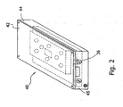
- Cartridge 40 may contain any type of fuel cell fuel, as discussed above.
- Cartridge 40 comprises housing top 42 and housing body 44.
- Body 44 is preferably configured and dimensioned to receive optional fuel bladder or fuel liner 46, as shown in FIG. 1 .
- Fuel liners are fully disclosed in commonly owned, co-pending United States patent application serial no. 10/629,004 , entitled “Fuel Cartridge with Flexible Liner,” filed on July 29, 2003.
- cartridge 40 is illustrated as having a rectangular prism shape.
- cartridge 40 can have any shape or form, e.g ., cylindrical or spherical, and the outer casing can be constructed out of a plastic or a metal.
- a portion of a connecting valve 36 is mounted on upstanding endwall 45 of body 44, with a corresponding portion of connecting valve 36 attached to the fuel cell or filling device.
- Endwall 45 defines slot 48, which is adapted to receive valve 36.
- Valve 36 can be used to fill cartridge 40 with fuel, and valve 36 can also be used to selectively transport fuel from cartridge 40 to the fuel cell.
- valve 36 preferably comprises two external flanges 51a,b that straddle endwall 45 to secure valve 36 in place.
- outer flange 51 a is flush with the outer surface of endwall 45, as shown.
- Slot 48 is preferably sealed with a sealing member (not shown) such as a plug, O-ring, a gasket or the like inserted into slot 48.
- the sealing member can be made from elastomeric, rubber or filler materials among other suitable sealing materials.
- Valve 36 or a portion thereof may also be sealed into slot 48 by any method known in the art, such as by ultrasonic welding, adhesive, etc.
- Valve 36 is preferably an automatic shut-off valve, such as a check valve, so that fuel cannot flow through valve 36 when cartridge 40 is not properly connected to a device, such as a filling reservoir or a fuel cell.
- a device such as a filling reservoir or a fuel cell.
- Valve 36 may include many different internal configurations, depending upon many factors, including the precise application of the fuel supply, e.g., residential versus industrial use, and the type of fuel stored in cartridge 40.
- Suitable shut-off valves include those disclosed in the parent '949 and '006 applications, both of which were previously incorporated by reference. Additional suitable valves are discussed in co-owned PCT application no. PCT/US 2005/04826 , entitled “Fuel Supply Systems Having Operational Resistance,” filed on February 16, 2005.
- valve 36 comprises a first valve component 50 and a corresponding second valve component 52.
- Second valve component 52 is configured to be fluidly connected to first valve component 50.
- first valve component 50 may be configured such that a portion of second valve component 52 is inserted into first valve component 50.
- first and second valve components 50, 52 are aligned with each other using any method known in the art, for example, by attaching or inserting valve components 50,52 to additional holders such as a sleeve or components on fuel supply 40 and/or the fuel cell or device.
- first valve component 50 is located on cartridge 40 and second valve component 52 is positioned on the device; in another embodiment, the configuration is reversed, with first valve component 50 located on the device and second valve component 52 positioned on cartridge 40.
- first valve component 50 includes a first housing 54 having a back end 51 and a front end 53.
- First housing 54 is generally cylindrical and made from a material that is effectively inert to the fluid or gas, i.e., is capable of withstanding lengthy exposure to the fluid or gas without substantial degradation, leaching, and/or contamination of the fuel.
- first housing 54 may be made from stainless steel. Additional suitable materials are discussed in commonly-owned US patent publication 2005/0116190, published on June 2, 2005 , entitled "Fuel Cell Supply Having Fuel Compatible Materials".
- First housing 54 preferably includes at least two inner diameters such that an inner wall 55 of first housing 54 forms a shoulder 57. Additionally, front end 53 of first valve component 50 is sized to receive a front end 71 of a second housing 68 of second valve component 52. Back end 51 of first housing 54 includes a relatively small opening 49 to allow the fluid or gas to pass into and/or out of valve 36.
- valve post 58 is fixedly attached to back end 51 of first housing 54.
- Valve post 58 is preferably a thin cylindrical body with an endcap 59 at its front end.
- valve post 58 is made of a material similar to or the same as that of first housing 54 so that valve post 58 may be readily affixed thereto using any method known in the art, such as welding, press fit or adhering with a fixative agent.
- valve sleeve 56 is slidably disposed within first housing 54 and around valve post 58.
- Valve sleeve 56 is also, preferably, made of a material that is effectively inert to the fuel.
- Valve sleeve 56 is sized and dimensioned to fit within first housing 54 so that valve sleeve 56 slides along inner wall 55.
- valve sleeve 56 is slip fit within first housing 54.
- a sleeve-sealing member 62 is disposed between valve sleeve 56 and inner wall 55 of first housing 54 so that no flow can occur between valve sleeve 56 and first housing 54.
- sleeve-sealing member 62 is an O-ring, although it may be any sealing element known in the art, such as a gasket or a highly viscous fluid.
- Valve sleeve 56 includes a cap 61 proportioned such that cap 61 cannot pass outer shoulder 57 when moving toward back end 51, i.e., outer shoulder 57 acts as a stop for valve sleeve 56 within first housing 54.
- An inner wall 63 of valve sleeve 56 is sized to define a flow path F 1 between inner wall 63 and valve post 58.
- valve sleeve 56 also has inner shoulder 65 that extends inwardly so that valve sleeve 56 cannot move past endcap 59 of valve post 58 when moving away from back end 51. Valve sleeve 56 is slidable between shoulder 57 and endcap 59.
- First valve component 50 includes several sealing elements to limit the flow therethrough to path F 1 when valve component 50 is open. While any number of sealing elements such as O-rings, gaskets, overmolded elastomeric portions, or viscous materials may be used, preferably first valve component 50 includes three such sealing elements, preferably O-rings.
- a post-sealing member 66 is disposed between valve post 58 and valve sleeve 56, preferably at or near shoulder 65. In other words, post-sealing member 66 is positioned within flow path F 1 to close flow path F 1 when first valve component 50 is closed.
- a face-sealing member 64 is disposed on a first face 90 of front end 53 of first valve component 50. Face seal 64 can also be located in second valve component 52.
- Face-sealing member 64 is sized and dimensioned to provide an inter-component seal when second valve component 52 is engaged with first valve component 50, i.e. , when first face 90 comes into contact with a second face 91 on a front end 71 of second valve member 52, face-sealing member 64 is in contact with both first face 90 and second face 91 to seal the interface of first and second valve components 50, 52.
- a spring 60 is disposed around valve post 58 and contacts a portion of valve sleeve 56 to bias valve sleeve to the closed position.
- spring 60 is disposed within a portion of valve sleeve 56.
- spring 60 may extend only to an end of valve sleeve 56, such that spring 60 is in contact with valve sleeve 56 but is not disposed within valve sleeve 56.
- Spring 60 may be any type of spring known in the art capable of biasing valve sleeve 56 toward front end 53, such as a stainless steel helical spring.
- Spring 60 preferably engages with an inner shoulder 69 of valve sleeve 56.
- the spring constant of spring 60 is selected to allow valve sleeve 56 to slide toward back end 51 only when a force greater than a predetermined threshold is applied by the insertion of second valve component 52.
- Second valve component 52 is generally a check valve and includes a second housing 68 having a front end 71 and a back end 73.
- Check valves are fully disclosed in the parent '949 and '006 applications, and as used in the present application a check valve has a slidable body biased into a sealing position with the valve body.
- second housing 68 is generally cylindrical and made from a material that is effectively inert to the fuel, such as stainless steel.
- Second housing 68 preferably includes at least two inner diameters such that an inner wall 77 of second housing 68 forms a housing shoulder 75.
- Front end 71 of second housing 68 is sized and dimensioned to be received within front end 53 of first housing 54 so that first valve component 50 may engage with second valve component 52.
- Valve plunger 70 is slidably disposed within second housing 68.
- Valve plunger 70 which is preferably made of an inert material, includes a plunger head 79 and a cylindrical rear portion 80 that defines a plunger spring compartment 78.
- Rear portion 80 does not extend the length of second housing 68, such that a plunger gap 82 is formed between rear portion 80 and back end 73 to allow valve plunger to move within second housing 68.
- Gap 82 also controls the maximum displacement of valve plunger 70.
- a plunger spring 72 contained within plunger spring compartment 78 extends to back end 73 of second housing 68. Similar to sleeve spring 60, plunger spring 72 biases valve plunger 70 towards front end 71 to close second valve component 52.
- plunger head 79 When not engaged with first valve component 50, plunger head 79 is preferably flush with second face 91, as shown in FIG. 3A .
- plunger head 79 may terminate slightly short of second face 91, or have any other configuration that either allows a minimum amount of force to open valve 36 or provides a minimum distance for valve plunger 70 to move in order to open valve 36.
- a second flow path F 2 is defined between outer-wall 81 and inner wall 77 of second housing 68.
- a plunger sealing member 74 Positioned within flow path F 2 at or near shoulder 76 is a plunger sealing member 74 to seal second valve component 52 in the closed position. Similar to sealing elements 62, 64, 66, sealing member 74 is preferably an O-ring, but may also be a gasket, overmolded elastomer, or the like.
- Valve plunger 70 also includes a plunger shoulder 76, which is sized and proportioned to cooperate with housing shoulder 75 to engage sealing member 74 to seal flow path F 2 .
- valve sleeve 56 and plunger 70 are the two elements that are biased and movable to open the seals in the valve component.
- valve 36 the opening sequence of valve 36 is as follows.
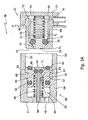
- FIG. 3A shows valve 36 separated, i.e., first and second valve components 50, 52 are disengaged from each other, for example, when cartridge 40 is disconnected from the device.
- sealing members 62, 66, 74 close flow paths F 1 and F 2 .
- Valve sleeve 56 and valve plunger 70 are biased into the closed positions.
- front end 71 of second valve component 52 is inserted into front end 53 of first valve component 50, for example, when cartridge 40 is initially connected to the device but is not yet fully introduced.
- face seal 64 is engaged with front end 71 of second valve component 52 and more particularly with the front end of biased second housing 68 to seal the interface of first and second valve components 50, 52.
- All other sealing members 62, 66, 72 continue closing off potential flow paths for the fluid or gas.
- Valve sleeve 56 remains biased to a closed position.
- valve plunger 70 remains biased to a closed position.
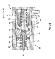
- first and second valve components 50, 52 are fully engaged, such as when cartridge 40 is completely introduced to the device.
- Stationary second housing 68 presses against biased valve sleeve 56 so that valve sleeve 56 is moved backward through gap 67, compressing spring 60 and opening first flow path F 1 .
- stationary valve post 58 pushes biased valve plunger 70 so that valve plunger 70 is translated distally through gap 82, compressing plunger spring 72 and opening second flow path F 2 .
- Post-sealing member 66 and plunger sealing member 74 are released to allow fluid or gas to flow through first and second flow paths, F 1 , F 2 , respectively.
- Sleeve-sealing member 62 and face-sealing member 64 remain engaged to isolate the flow to paths F 1 and F 2 .
- valve 36 The closing sequence of valve 36 is essentially the reverse process of the above-described opening sequence.
- spring 60 and plunger spring 72 release their stored energy, thereby returning biased valve sleeve 56 and biased valve plunger 70 to their original sealing positions.
- Post-sealing member 66 and plunger-sealing member 74 are once again engaged to close off first and second flow paths, F 1 , F 2 , respectively.
- Sleeve-sealing member 62 is always in the sealed position in this embodiment and face-sealing member 64 remain engaged to provide the inter-component seal.
- First and second valve components 50, 52 are then completely disengaged. As first and second flow paths F 1 and F 2 are sealed very near the interface of first and second valve components 50, 52 the fluid volume between seals 66 and 72 is minimized.
- first valve component 50 opens simultaneously with second valve component 52.
- advantage may be found in opening the flow path to the device prior to opening the flow path to cartridge 40, for example to ensure that the device is prepared to receive fluid or gas prior to accessing the stores of cartridge 40.
- This sequential opening may be attained by simply adjusting the length of valve post 58 and/or second housing 68 and plunger head 79.
- valve post 58 may be shortened or second housing 68 may be lengthened so that plunger head 79 is recessed therewithin. In such a case, second housing 68 moves valve sleeve 56 prior to valve post 58 engaging with valve plunger 70.
- second housing 68 may be recessed within second valve component 52 or one of valve post 58 or valve plunger 79 may be lengthened so that valve post 58 translates valve plunger 79 prior to second housing 68 engaging with valve sleeve 56.
- one of springs 60 or 72 may provide a lower spring force than the other so that less force is required to open either valve post 56 or valve plunger 79, respectively. Any of these structures or combinations thereof may also result in one valve component having a longer stroke to close its flow path than the other valve component so that one valve component has a longer closing sequence than the other valve component.
- first valve component 50 and second valve component 52 are sequential, i.e., one valve component closes later or more slowly than the other, the later-closing valve component may tend to draw residual fluid or gas within its flow path away from the interface of the two valve components 50, 52.
- This tendency commonly referred to as "suck-back", occurs when the piston-like motion of a part within a fluid-carrying chamber of a closed system creates or increases the volume of an empty space within the chamber, thereby lowering the pressure of the fluid within the chamber. Fluid in fluidly-connected channels is drawn, i.e., sucked, into the low-pressure chamber.
- valve sleeve 56 moves toward front end 53 after valve plunger 70 has already been positioned to seal second flow path F 2 .
- the motion of valve sleeve 56 increases the volume of the back end 95 of first flow path F 1 between valve sleeve 56 and back end 51 of first valve component 50.
- opening 49 includes a one-way valve, such as a check valve, a duckbill valve or a flap, so that the flow path between plunger seal 74 and opening 49 is effectively a closed system once plunger seal 74 is engaged, the movement of valve sleeve 56 and increased volume in back end 95 create a low pressure region in back end 95.
- any fluid in front of plunger seal 74 is pulled towards back end 95 until sleeve seal 66 engages to close first flow path F 1 .
- the delay between the closing of the two flow paths F 1 , F 2 may be selected so that substantially all of the fluid in front of plunger seal 74 is drawn into first flow path F 1 to reside behind sleeve seal 62 when first flow path F 1 is completely closed.
- a similar but oppositely-oriented process occurs when the stroke of second valve component 52 is longer than that of first valve component 50.
- first and second valve components 50, 52 may be different, with the larger diameter valve component closing later than the other valve component. Also, if the opening of one valve component displaces a greater volume of fluid than the other valve component, then the valve component that displaces the greater volume will close later and create suck-back. Longer stroke only applies when the diameters are equal or the longer stroke diameter is greater.
- valve 136 Similar in many respects to valve 36 shown and discussed above with respect to FIGS. 3A-3C , valve 136 includes a first valve component 150 attached to either the fuel cartridge or the device and configured to be connected to a corresponding second valve component 152 attached to the other of the fuel cartridge or the device.
- Valve sleeve 156 may be made from an elastomeric material, such as rubber, urethane, silicone and the like. If made from an elastomeric material, valve sleeve 156 itself acts as a spring and as a seal for flow path F 1 .
- first flow path F1 When deformed due to an external force, such as by compression due to mating with second valve component 152, first flow path F1 is opened and energy is stored within the material of valve sleeve 156. When the external force is removed, valve sleeve 56 releases its stored energy and returns to its original shape to re-seal flow path F 1 such that no additional spring, such as spring 60 or plunger spring 72 as shown in FIGS. 3A-C , is required to re-establish the seal.
- an external force such as by compression due to mating with second valve component 152
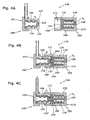
- FIG. 4A shows first valve component 150 completely separated from second valve component 152, such that both first valve component 150 and second valve component 152 are sealed.
- First valve component 150 includes a first housing 154 having deformable valve sleeve 156 disposed therein.
- a first flow path F 1 is defined between first housing 154 and valve sleeve 156.
- First housing 154 includes a shoulder 157 formed near the interface of first valve component 150 and second valve component 152.
- valve sleeve 156 is configured with a shoulder 165 to engage with shoulder 157 to seal first flow path F 1 .
- second valve component 152 includes a second housing 168 configured to receive an end of first housing 154.
- a deformable valve plunger 170 is disposed within second housing 168 and is configured at one end with a shoulder 169.
- a valve post 158 is positioned within valve plunger 170.
- a second flow path F 2 is defined between valve plunger 170 and valve post 158.
- One end of valve post 158 terminates as a valve post cap 159.
- Valve post cap 159 is rigid and includes a shoulder 176 that is configured to engage with shoulder 169 such that shoulder 176 and shoulder 169 act as sealing surfaces to seal flow path F 2 .
- FIG. 4B shows the first stage of connection of first valve component 150 and second valve component 152, where first housing 154 has been inserted into second housing 168. At this stage, neither valve sleeve 156 nor valve plunger 170 have been deformed, so first flow path and second flow path are still sealed. However, first housing 154 abuts valve plunger 170 at the interface between first valve component 150 and second valve component 152 to form an intercomponent seal.
- FIG. 4C shows the second stage of connection of first valve component 150 and second valve component 152, where first housing 154 has been fully inserted into second housing 168.
- Valve post cap 159 presses against and deforms valve sleeve 156, thereby separating shoulder 157 from shoulder 165 to open first flow path F 1 .
- first housing 154 is pressed against and deforms valve plunger 170, thereby separating shoulder 176 and shoulder 169 to open second flow path F 2 .
- first housing 154 is removed from second housing 168 in a two-stage process similar to the procedure for opening valve 136.
- valve post cap 159 stops exerting a force on valve sleeve 156, allowing valve sleeve 156 to return to its original configuration.
- shoulder 157 and shoulder 165 again engage to seal first flow path F 1 .
- first housing 154 stops pressing against valve plunger 170, allowing valve plunger 170 to return to its original configuration.
- shoulder 176 and shoulder 169 again engage to seal second flow path F 2 .
- the interface seal remains intact at this point.
- first housing 154 is fully removed from second housing 168 such that first housing 154 no longer abuts deformable valve plunger 170.
- the intercomponent seal is broken, and first valve component 150 and second valve component 152 are completely separated.
- FIGS. 5A and 5B show another alternate embodiment for a valve component 251.
- Valve component 251 forms the female part of a separable valve, such as valve 36 and valve 136.
- valve component 251 is positioned on cartridge 40 to be mated with a second valve component on the device; however, valve component 251 may also be used on the device.
- Valve component 251 includes a housing 254, which may be made from any material known in the art, such as stainless steel, plastics or resins. Housing 254 is configured to slidably contain a valve plunger 270. A flow path F is defined between housing 254 and valve plunger 270.
- Housing 254 is configured with a first sealing surface 269 that corresponds with a second sealing surface 276 defined by the shape of valve plunger 270.
- spring 272 biases valve plunger 270 so that a seal is formed by compressing an O-ring 266 between first sealing surface 269 and second sealing surface.276.
- Spring 272 resides partially within housing 254 and partially within a cap 283 attached to housing 254.
- the male part of the valve is configured to be inserted into housing 254, with an interface O-ring 264 sealing the interface of the male part and valve component 251.
- An O-ring retainer 285 is also provided to secure interface O-ring 264 in position.
- housing 254 When the male part is removed from housing 254, residual fluid remains within flow path F.
- housing 254 is made as short as practicable, preferably between about 4 mm and 8 mm for use with typical fuel cell cartridges such as cartridge 40. Shortening housing 254 reduces the overall length of flow path F, which consequently reduces the volume of flow path F. Reduction of the length of the flow path also reduces the amount of residual fuel in the fuel supply.
- cap 283 also includes a plurality of openings 284. Openings 284 permit residual fluid between plunger O-ring 266 and cap 283 to drain back into the fluid reservoir within fuel cartridge 40 or to drain from the fuel supply to minimize the amount of unusable fuel. Therefore, when valve component 251 is reconnected with the male part of the valve, no residual fluid remains within flow path F to escape during connection or to inhibit a secure connection of the male part with valve component 251.
- openings 284 are maximized, as openings 284 also allow for the fluid within the fuel supply to be drawn into valve component 251. Openings 284 assist in the complete removal of fuel from the fuel supply, such as when the fuel supply is nearly empty so that very little fuel remains therein. Large openings 284 allow the distance from openings 284 to plunger O-ring 266 to be minimized. As such, less pressure is required to draw fuel into valve component 251.
- FIG. 10/679,756 Another suitable valve adapted to minimize the residual fuel in the fuel supply is disclosed in BIC-071.
- FIG. 10/679,756 Another suitable valve adapted to minimize the residual fuel in the fuel supply is disclosed in BIC-071.
- FIG. 10/679,756 Another suitable valve adapted to minimize the residual fuel in the fuel supply is disclosed in BIC-071.
- FIG. 10/679,756 Another suitable valve adapted to minimize the residual fuel in the fuel supply is disclosed in BIC-071.
- absorbent material may be included in back end 95 or at the interface between first and second valve components 50, 52.
- cartridge 40 may have no liner, in which case valve 36 would communicate directly with an interior compartment of cartridge 40.
- different types of springs can be used in conjunction with the valves disclosed herein.
- the valves can be manually actuated or opened by the user or by user operated magnets.
- a filter located upstream of the valves described above to keep particulate(s) or fibers out of the valves can be included.
- Suitable filters include, but are not limited to, hydrophilic micro-membranes having a pore size sufficient to keep particulates or other solid objects out of the valves, which are wettable by the fuel contained in the fuel supplies.
- Such filter can be used with any embodiments described herein and described in the parent application, which has already been incorporated by reference. Additionally, in the embodiments described above one of the valve components may not have an internal seal, e.g., one valve component can be a flow conduit or a canula.
Landscapes
- Engineering & Computer Science (AREA)
- General Engineering & Computer Science (AREA)
- Mechanical Engineering (AREA)
- Sustainable Development (AREA)
- Sustainable Energy (AREA)
- Chemical & Material Sciences (AREA)
- Chemical Kinetics & Catalysis (AREA)
- Electrochemistry (AREA)
- General Chemical & Material Sciences (AREA)
- Life Sciences & Earth Sciences (AREA)
- Manufacturing & Machinery (AREA)
- Fuel Cell (AREA)
- Containers And Packaging Bodies Having A Special Means To Remove Contents (AREA)
Claims (22)
- Ventil, das aufweist:eine erste Ventilkomponente (50), die entweder mit einer Brennstoffversorgung (40) oder einer Vorrichtung verbindbar ist;eine zweite Ventilkomponente (52), mit der anderen einer Brennstoffversorgung (40) oder einer Vorrichtung verbindbar ist, wobei eine Ventilkomponente aufgebaut ist, um mit der anderen Ventilkomponente zusammen zu passen;ein Zwischenkomponentendichtungselement (64), das zwischen einer ersten Ventilkomponentenseite (90) und einer zweiten Ventilkomponentenseite (91) angeordnet ist;wobei jede Ventilkomponente (50, 52) ein Gehäuse (54, 68), einen beweglichen Innenkörper (56, 70) und einen Strömungsweg aufweist, wobei der bewegliche Innenkörper (56, 70) mit einer Dichtungsoberfläche (66, 74) zusammenwirkt, um innerhalb des Strömungswegs jeder Ventilkomponente (50, 52) eine Dichtung zu bilden, wenn die Ventilkomponenten (50, 52) unverbunden sind, und wobei das Zwischenkomponentendichtungselement (64) während der Verbindung eine Zwischenkomponentendichtung zwischen der ersten Ventilkomponente (50) und der zweiten Ventilkomponente (52) bildet und die Dichtungen in den Ventilkomponenten (50, 52) sich öffnen,dadurch gekennzeichnet, dassein hinteres Ende (51) einer der Ventilkomponenten (50) ein Einwegventil aufweist, das über ein Fluid mit dem Strömungsweg verbunden ist, so dass eine Rücksogwirkung erzeugt wird, wenn die Ventilkomponente (50) eine Dichtung wieder herstellt.
- Ventil nach Anspruch 1, wobei die Vorrichtung eine Brennstoffzelle aufweist.
- Ventil nach Anspruch 1 oder 2, wobei die Vorrichtung eine Brennstoffversorgungsfüllvorrichtung aufweist.
- Ventil nach einem der Ansprüche 1 bis 3, wobei eine Ventilkomponente (52) in der anderen Ventilkomponente (50) aufgenommen ist.
- Ventil nach einem der Ansprüche 1 bis 4, das ferner ein Dichtungselement (62, 74) aufweist, das benachbart zu der Dichtungsoberfläche positioniert ist, wobei der bewegliche Innenkörper (56, 70) vorgespannt ist und in dem Gehäuse verschiebbar ist, und wobei der bewegliche Innenkörper (56, 70) mit dem Dichtungselement (62, 74) und der Dichtungsoberfläche zusammenwirkt, um den Strömungsweg zu schließen.
- Ventil nach einem der Ansprüche 1 bis 5, wobei der bewegliche Innenkörper verformbar ist.
- Ventil nach einem der Ansprüche 1 bis 6, wobei der bewegliche Innenkörper elastomer ist.
- Ventil nach einem der Ansprüche 1 bis 7, wobei der bewegliche Innenkörper den Strömungsweg abdichtet.
- Ventil nach einem der Ansprüche 1 bis 8, wobei eine der Ventilkomponenten (50, 52) aufweist:einen Ventilstab (58), der fest an dem Ventilkomponentengehäuse (54) angebracht ist,eine Ventilhülse (56), die um den Ventilstab (58) herum verschiebbar angeordnet ist, wobei der Strömungsweg zwischen der Ventilhülse (56) und dem Ventilstab (58) definiert ist, undwobei wenigstens eine Stabdichtungsoberfläche (66) nahe an dem Strömungsweg angeordnet ist, und wobei der Ventilstab (58) und die Ventilhülse (56) mit der Stabdichtungsoberfläche (66) zusammenwirken, um den Strömungsweg abzudichten.
- Ventil nach Anspruch 9, wobei die Ventilhülse (56) zu dem Ventilkomponentengehäuse (54) abgedichtet ist.
- Ventil nach Anspruch 9 oder 10, wobei wenigstens ein Hülsendichtungselement (62) zwischen der Ventilhülse (56) und dem Ventilkomponentengehäuse (54) angeordnet ist.
- Ventil nach einem der Ansprüche 9 bis 11, wobei die andere Ventilkomponente (52) ein Rückschlagventil aufweist.
- Ventil nach einem der Ansprüche 1 bis 12, das ferner eine Kappe (283) aufweist, die an einem Ende des Gehäuses angebracht ist, wobei die Kappe (283) wenigstens eine Öffnung (284) darin ausgebildet hat.
- Ventil nach einem der Ansprüche 1 bis 13, wobei eine Länge des Ventilkomponentengehäuses von etwa 4 mm bis etwa 8 mm reicht.
- Ventil nach einem der Ansprüche 1 bis 14, wobei eine der Ventilkomponenten (50, 52) ein Rückschlagventil aufweist.
- Ventil nach einem der Ansprüche 1 bis 15, wobei die ersten und zweiten Ventilkomponenten (50, 52) sich gleichzeitig öffnen.
- Ventil nach einem der Ansprüche 1 bis 15, wobei die ersten und zweiten Ventilkomponenten (50, 52) sich nacheinander öffnen.
- Ventil nach einem der Ansprüche 1 bis 17, wobei die ersten und zweiten Ventilkomponenten (50, 52) sich nacheinander schließen.
- Ventil nach Anspruch 18, wobei das Schließen der später geschlossenen Ventilkomponente (50) ein Fluid innerhalb der früher geschlossenen Ventilkomponente (52) und der später geschlossenen Ventilkomponente (50) in Richtung eines hinteren Endes (51) der später geschlossenen Ventilkomponente (50) saugt.
- Ventil nach Anspruch 19, wobei das hintere Ende (51), welches das Einwegventil aufweist, das über ein Fluid mit dem Strömungsweg verbunden ist, in der später geschlossenen Ventilkomponente (50) angeordnet ist.
- Ventil, das aufweist:eine erste Ventilkomponente (50), die entweder mit einer Brennstoffversorgung (40) oder einer Vorrichtung verbindbar ist;eine zweite Ventilkomponente (52), mit der anderen einer Brennstoffversorgung (40) oder einer Vorrichtung verbindbar ist, wobei eine erste Ventilkomponentenseite (90) aufgebaut ist, um mit der zweiten Ventilkomponentenseite (90) zusammen zu passen, undein Zwischenkomponentendichtungselement (64), das zwischen der ersten Ventilkomponentenseite (90) und der zweiten Ventilkomponentenseite (91) angeordnet ist;wobei jede Ventilkomponente (50, 52) einen ortsfesten Körper (58, 68) und einen vorgespannten verschiebbaren Körper (56, 70) und einen Strömungsweg zwischen dem ortsfesten Körper und dem vorgespannten verschiebbaren Körper aufweist, wobei der vorgespannte verschiebbare Körper (56, 70) mit einer Dichtungsoberfläche zusammenwirkt, um innerhalb jeder Ventilkomponente (50, 52) eine Innendichtung zu bilden, und wobei der ortsfeste Körper (58) einer Ventilkomponente (50) während der Verbindung den vorgespannten verschiebbaren Körper (70) der anderen Ventilkomponente (52) bewegt, und wobei die erste Ventilkomponente (50) und die zweite Ventilkomponente (52) während der Verbindung eine Zwischenkomponentendichtung an einer Grenzfläche der ersten Ventilkomponentenseite (90) und der zweiten Ventilkomponentenseite (91) bilden,dadurch gekennzeichnet, dassdie ersten und zweiten Ventilkomponenten (50, 52) sich nacheinander schließen, so dass in dem sich später schließenden Ventil (50, 52) eine Rücksogwirkung erzeugt wird, wobei das sich später schließende Ventil beim Schließen ein größeres Fluidvolumen verdrängt als die andere Ventilkomponente.
- Ventil nach Anspruch 21, wobei die sich später schließende Ventilkomponente (50) einen längeren Hub als die andere Ventilkomponente (52) hat.
Applications Claiming Priority (2)
| Application Number | Priority Date | Filing Date | Title |
|---|---|---|---|
| US11/391,578 US7617842B2 (en) | 2003-07-29 | 2006-03-28 | Valves for fuel cartridges |
| PCT/US2007/007655 WO2007126869A2 (en) | 2006-03-28 | 2007-03-27 | Valves for fuel cartridges |
Publications (3)
| Publication Number | Publication Date |
|---|---|
| EP2002497A2 EP2002497A2 (de) | 2008-12-17 |
| EP2002497A4 EP2002497A4 (de) | 2010-12-29 |
| EP2002497B1 true EP2002497B1 (de) | 2015-06-03 |
Family
ID=38656036
Family Applications (1)
| Application Number | Title | Priority Date | Filing Date |
|---|---|---|---|
| EP07754208.2A Not-in-force EP2002497B1 (de) | 2006-03-28 | 2007-03-27 | Ventile für brennstoffkassetten |
Country Status (11)
| Country | Link |
|---|---|
| US (1) | US7617842B2 (de) |
| EP (1) | EP2002497B1 (de) |
| JP (1) | JP5503964B2 (de) |
| KR (1) | KR101432142B1 (de) |
| CN (1) | CN101411006B (de) |
| AU (1) | AU2007245157A1 (de) |
| BR (1) | BRPI0709208A2 (de) |
| CA (1) | CA2646724C (de) |
| MX (1) | MX2008012021A (de) |
| MY (1) | MY144656A (de) |
| WO (1) | WO2007126869A2 (de) |
Families Citing this family (27)
| Publication number | Priority date | Publication date | Assignee | Title |
|---|---|---|---|---|
| CN1998105A (zh) * | 2004-07-08 | 2007-07-11 | 直接甲醇燃料电池公司 | 燃料电池盒和燃料输送系统 |
| US8196894B2 (en) * | 2006-01-06 | 2012-06-12 | Societe Bic | Check valves for fuel cartridges |
| US20080131740A1 (en) * | 2006-01-19 | 2008-06-05 | Manuel Arranz Del Rosal | Fuel cartridge coupling valve |
| US20080029156A1 (en) * | 2006-01-19 | 2008-02-07 | Rosal Manuel A D | Fuel cartridge |
| JP2008084809A (ja) * | 2006-08-29 | 2008-04-10 | Yamaha Motor Co Ltd | 水素供給用配管の接続構造 |
| WO2008055346A1 (en) * | 2006-11-07 | 2008-05-15 | Angstrom Power Incorporated | Magnetic fluid coupling assemblies and methods |
| TW200935650A (en) * | 2008-02-04 | 2009-08-16 | Coretronic Corp | Switch valve applied to a cartridge of a fuel cell |
| EP2262477A1 (de) * | 2008-03-04 | 2010-12-22 | F. Hoffmann-La Roche AG | Verfahren zur herstellung konzentrierter mizellarer lösungen mit wasseranteil |
| US8986404B2 (en) | 2009-11-03 | 2015-03-24 | Societe Bic | Gas generator with starter mechanism and catalyst shield |
| US8636826B2 (en) | 2009-11-03 | 2014-01-28 | Societe Bic | Hydrogen membrane separator |
| US20100124689A1 (en) * | 2008-11-20 | 2010-05-20 | Mti Microfuel Cells, Inc. | System to reservoir connector |
| CN102256741A (zh) * | 2008-12-17 | 2011-11-23 | 克斯美库股份有限公司 | 带液力耦合器的紧固系统 |
| US20110003225A1 (en) * | 2009-07-06 | 2011-01-06 | Honeywell International Inc. | Recharging valve for a fuel cell |
| DE102011010641A1 (de) * | 2011-02-09 | 2012-08-09 | Emitec France S.A.S | Injektor für eine Harnstoff-Wasser-Lösung |
| CN102709505B (zh) * | 2012-07-05 | 2014-05-28 | 刘立文 | 一种可调蓄电池防爆安全阀 |
| CN103807543B (zh) * | 2012-11-12 | 2015-12-02 | 沁园集团股份有限公司 | 一种水路的活动连接装置 |
| CN105120718B (zh) * | 2012-12-30 | 2018-04-10 | 阿塞里克股份有限公司 | 在饮料制备机中使用的阀门机构 |
| CN104565632B (zh) * | 2013-10-21 | 2016-08-24 | 丹阳市飞越车辆附件有限公司 | 电容器填充气体防掺杂气路连接器 |
| KR101509746B1 (ko) | 2013-12-05 | 2015-04-07 | 현대자동차 주식회사 | 선택적 촉매 환원 장치용 요소수 주입 장치 |
| US10094349B2 (en) * | 2014-05-08 | 2018-10-09 | Hitachi, Ltd. | Fluid valve assembly |
| CN111677952B (zh) * | 2019-03-06 | 2022-08-23 | 奥动新能源汽车科技有限公司 | 冷媒插接件接头、冷媒插接件以及电连接器 |
| CN115574173A (zh) * | 2021-07-06 | 2023-01-06 | 瑞肯耐特流体控制系统(镇江)有限公司 | 阴连接器和连接器组件 |
| IT202100030386A1 (it) * | 2021-12-01 | 2023-06-01 | Euromeccanica Mazzer S R L | Contenitore con valvola per stoccaggio, dispensazione e trasporto di additivi per carburanti di aeromobili, kit associato e metodo |
| CN116964844A (zh) | 2022-01-21 | 2023-10-27 | 宁德时代新能源科技股份有限公司 | 储能系统 |
| JP7826038B2 (ja) | 2022-02-09 | 2026-03-09 | 三菱重工エンジン&ターボチャージャ株式会社 | エンジン及びエンジンの制御方法 |
| TWI820634B (zh) * | 2022-03-14 | 2023-11-01 | 伍隆國際有限公司 | 流體接合結構 |
| JP7786423B2 (ja) * | 2023-04-05 | 2025-12-16 | トヨタ自動車株式会社 | カートリッジとガス消費装置の連結構造 |
Family Cites Families (24)
| Publication number | Priority date | Publication date | Assignee | Title |
|---|---|---|---|---|
| CH626696A5 (de) * | 1977-03-19 | 1981-11-30 | Argus Gmbh | |
| US4261956A (en) | 1979-06-13 | 1981-04-14 | Engelhard Minerals & Chemicals Corporation | Cartridge for gas generator |
| JP2802787B2 (ja) * | 1988-10-21 | 1998-09-24 | 株式会社コスメック | 流体用急速継手 |
| JP2559233Y2 (ja) * | 1993-07-07 | 1998-01-14 | 日東工器株式会社 | 管継手 |
| US5709243A (en) * | 1995-11-20 | 1998-01-20 | Aeroquip Corporation | Low spill female coupling |
| US5791366A (en) * | 1996-01-16 | 1998-08-11 | Preece Incorporated | Frangible quick disconnect coupling |
| US5945231A (en) | 1996-03-26 | 1999-08-31 | California Institute Of Technology | Direct liquid-feed fuel cell with membrane electrolyte and manufacturing thereof |
| US5723229A (en) | 1996-07-08 | 1998-03-03 | Motorola, Inc. | Portable fuel cell device including a water trap |
| US6161578A (en) | 1996-10-09 | 2000-12-19 | Colder Products Company | Low spill high flow quick coupling valve assembly |
| US5794657A (en) * | 1997-02-07 | 1998-08-18 | Oberg; Gordon D. | Safety check valve for fuel delivery system |
| US5992008A (en) | 1998-02-10 | 1999-11-30 | California Institute Of Technology | Direct methanol feed fuel cell with reduced catalyst loading |
| US6032691A (en) * | 1999-03-29 | 2000-03-07 | Kaylynn, Inc. | Valve assembly |
| JP3668069B2 (ja) | 1999-09-21 | 2005-07-06 | 株式会社東芝 | 燃料電池用液体燃料収容容器および燃料電池 |
| US6708740B2 (en) | 2000-04-07 | 2004-03-23 | Kaj Wessberg | Method when tanking up using a tanking up valve |
| JP3512718B2 (ja) * | 2000-08-10 | 2004-03-31 | 日東工器株式会社 | 管継手 |
| WO2002099916A2 (en) | 2001-06-01 | 2002-12-12 | Polyfuel, Inc | Fuel cell assembly for portable electronic device and interface, control, and regulator circuit for fuel cell powered electronic device |
| US20030035984A1 (en) | 2001-08-15 | 2003-02-20 | Colborn Jeffrey A. | Metal fuel cell system for providing backup power to one or more loads |
| US6916007B2 (en) | 2001-09-28 | 2005-07-12 | Colder Products Company | Closure valve apparatus for fluid dispensing |
| JP3862539B2 (ja) * | 2001-10-09 | 2006-12-27 | 株式会社コスメック | 圧力流体の給排方法 |
| US6924054B2 (en) | 2001-10-29 | 2005-08-02 | Hewlett-Packard Development Company L.P. | Fuel supply for a fuel cell |
| US6686077B2 (en) | 2001-11-21 | 2004-02-03 | The Boeing Company | Liquid hetero-interface fuel cell device |
| JP2004360837A (ja) * | 2003-06-06 | 2004-12-24 | Kosmek Ltd | 急速継手 |
| US7537024B2 (en) * | 2003-07-29 | 2009-05-26 | Societe Bic | Fuel cartridge with connecting valve |
| US7059582B2 (en) | 2003-12-01 | 2006-06-13 | Societe Bic | Fuel cell supply having fuel compatible materials |
-
2006
- 2006-03-28 US US11/391,578 patent/US7617842B2/en not_active Expired - Fee Related
-
2007
- 2007-03-27 JP JP2009502969A patent/JP5503964B2/ja not_active Expired - Fee Related
- 2007-03-27 WO PCT/US2007/007655 patent/WO2007126869A2/en not_active Ceased
- 2007-03-27 KR KR1020087023702A patent/KR101432142B1/ko not_active Expired - Fee Related
- 2007-03-27 EP EP07754208.2A patent/EP2002497B1/de not_active Not-in-force
- 2007-03-27 CA CA2646724A patent/CA2646724C/en not_active Expired - Fee Related
- 2007-03-27 AU AU2007245157A patent/AU2007245157A1/en not_active Abandoned
- 2007-03-27 MX MX2008012021A patent/MX2008012021A/es active IP Right Grant
- 2007-03-27 BR BRPI0709208-3A patent/BRPI0709208A2/pt not_active IP Right Cessation
- 2007-03-27 CN CN2007800109708A patent/CN101411006B/zh not_active Expired - Fee Related
-
2008
- 2008-09-18 MY MYPI20083649A patent/MY144656A/en unknown
Also Published As
| Publication number | Publication date |
|---|---|
| CA2646724A1 (en) | 2007-11-08 |
| EP2002497A4 (de) | 2010-12-29 |
| AU2007245157A1 (en) | 2007-11-08 |
| WO2007126869A2 (en) | 2007-11-08 |
| KR20080104162A (ko) | 2008-12-01 |
| EP2002497A2 (de) | 2008-12-17 |
| JP2009531833A (ja) | 2009-09-03 |
| US20060196562A1 (en) | 2006-09-07 |
| CN101411006A (zh) | 2009-04-15 |
| BRPI0709208A2 (pt) | 2011-06-28 |
| KR101432142B1 (ko) | 2014-08-21 |
| CN101411006B (zh) | 2013-01-02 |
| CA2646724C (en) | 2013-10-22 |
| WO2007126869A3 (en) | 2008-07-24 |
| MY144656A (en) | 2011-10-31 |
| JP5503964B2 (ja) | 2014-05-28 |
| US7617842B2 (en) | 2009-11-17 |
| MX2008012021A (es) | 2008-11-04 |
Similar Documents
| Publication | Publication Date | Title |
|---|---|---|
| EP2002497B1 (de) | Ventile für brennstoffkassetten | |
| EP2179210B1 (de) | Nicht austauschbare anschlussventile für brennstoffkartuschen | |
| CN100561031C (zh) | 具有连接阀的燃料电池系统及其连接阀 | |
| US7762278B2 (en) | Valves for fuel cartridges |
Legal Events
| Date | Code | Title | Description |
|---|---|---|---|
| PUAI | Public reference made under article 153(3) epc to a published international application that has entered the european phase |
Free format text: ORIGINAL CODE: 0009012 |
|
| AK | Designated contracting states |
Kind code of ref document: A2 Designated state(s): AT BE BG CH CY CZ DE DK EE ES FI FR GB GR HU IE IS IT LI LT LU LV MC MT NL PL PT RO SE SI SK TR |
|
| AX | Request for extension of the european patent |
Extension state: AL BA HR MK RS |
|
| 17P | Request for examination filed |
Effective date: 20081205 |
|
| RBV | Designated contracting states (corrected) |
Designated state(s): AT BE BG CH CY CZ DE DK EE ES FI FR GB GR HU IE IS IT LI LT LU LV MC MT NL PL PT RO SE SI SK TR |
|
| A4 | Supplementary search report drawn up and despatched |
Effective date: 20101126 |
|
| RIC1 | Information provided on ipc code assigned before grant |
Ipc: H01M 8/04 20060101ALI20101122BHEP Ipc: H01M 2/12 20060101AFI20080929BHEP |
|
| 17Q | First examination report despatched |
Effective date: 20120516 |
|
| DAX | Request for extension of the european patent (deleted) | ||
| REG | Reference to a national code |
Ref country code: DE Ref legal event code: R079 Ref document number: 602007041664 Country of ref document: DE Free format text: PREVIOUS MAIN CLASS: H01M0002120000 Ipc: F16L0037320000 |
|
| RIC1 | Information provided on ipc code assigned before grant |
Ipc: F16L 37/32 20060101AFI20141016BHEP Ipc: F16K 15/06 20060101ALI20141016BHEP Ipc: H01M 8/04 20060101ALI20141016BHEP Ipc: H01M 8/10 20060101ALN20141016BHEP Ipc: H01M 2/12 20060101ALI20141016BHEP |
|
| GRAP | Despatch of communication of intention to grant a patent |
Free format text: ORIGINAL CODE: EPIDOSNIGR1 |
|
| INTG | Intention to grant announced |
Effective date: 20141222 |
|
| GRAS | Grant fee paid |
Free format text: ORIGINAL CODE: EPIDOSNIGR3 |
|
| GRAA | (expected) grant |
Free format text: ORIGINAL CODE: 0009210 |
|
| AK | Designated contracting states |
Kind code of ref document: B1 Designated state(s): AT BE BG CH CY CZ DE DK EE ES FI FR GB GR HU IE IS IT LI LT LU LV MC MT NL PL PT RO SE SI SK TR |
|
| REG | Reference to a national code |
Ref country code: GB Ref legal event code: FG4D |
|
| REG | Reference to a national code |
Ref country code: CH Ref legal event code: EP |
|
| RAP2 | Party data changed (patent owner data changed or rights of a patent transferred) |
Owner name: INTELLIGENT ENERGY LIMITED |
|
| REG | Reference to a national code |
Ref country code: AT Ref legal event code: REF Ref document number: 730100 Country of ref document: AT Kind code of ref document: T Effective date: 20150715 Ref country code: IE Ref legal event code: FG4D |
|
| REG | Reference to a national code |
Ref country code: DE Ref legal event code: R096 Ref document number: 602007041664 Country of ref document: DE Effective date: 20150716 |
|
| REG | Reference to a national code |
Ref country code: AT Ref legal event code: MK05 Ref document number: 730100 Country of ref document: AT Kind code of ref document: T Effective date: 20150603 |
|
| PG25 | Lapsed in a contracting state [announced via postgrant information from national office to epo] |
Ref country code: ES Free format text: LAPSE BECAUSE OF FAILURE TO SUBMIT A TRANSLATION OF THE DESCRIPTION OR TO PAY THE FEE WITHIN THE PRESCRIBED TIME-LIMIT Effective date: 20150603 Ref country code: LT Free format text: LAPSE BECAUSE OF FAILURE TO SUBMIT A TRANSLATION OF THE DESCRIPTION OR TO PAY THE FEE WITHIN THE PRESCRIBED TIME-LIMIT Effective date: 20150603 Ref country code: FI Free format text: LAPSE BECAUSE OF FAILURE TO SUBMIT A TRANSLATION OF THE DESCRIPTION OR TO PAY THE FEE WITHIN THE PRESCRIBED TIME-LIMIT Effective date: 20150603 |
|
| REG | Reference to a national code |
Ref country code: NL Ref legal event code: MP Effective date: 20150603 |
|
| REG | Reference to a national code |
Ref country code: LT Ref legal event code: MG4D |
|
| PG25 | Lapsed in a contracting state [announced via postgrant information from national office to epo] |
Ref country code: BG Free format text: LAPSE BECAUSE OF FAILURE TO SUBMIT A TRANSLATION OF THE DESCRIPTION OR TO PAY THE FEE WITHIN THE PRESCRIBED TIME-LIMIT Effective date: 20150903 Ref country code: AT Free format text: LAPSE BECAUSE OF FAILURE TO SUBMIT A TRANSLATION OF THE DESCRIPTION OR TO PAY THE FEE WITHIN THE PRESCRIBED TIME-LIMIT Effective date: 20150603 Ref country code: GR Free format text: LAPSE BECAUSE OF FAILURE TO SUBMIT A TRANSLATION OF THE DESCRIPTION OR TO PAY THE FEE WITHIN THE PRESCRIBED TIME-LIMIT Effective date: 20150904 Ref country code: LV Free format text: LAPSE BECAUSE OF FAILURE TO SUBMIT A TRANSLATION OF THE DESCRIPTION OR TO PAY THE FEE WITHIN THE PRESCRIBED TIME-LIMIT Effective date: 20150603 |
|
| PG25 | Lapsed in a contracting state [announced via postgrant information from national office to epo] |
Ref country code: EE Free format text: LAPSE BECAUSE OF FAILURE TO SUBMIT A TRANSLATION OF THE DESCRIPTION OR TO PAY THE FEE WITHIN THE PRESCRIBED TIME-LIMIT Effective date: 20150603 |
|
| PG25 | Lapsed in a contracting state [announced via postgrant information from national office to epo] |
Ref country code: IS Free format text: LAPSE BECAUSE OF FAILURE TO SUBMIT A TRANSLATION OF THE DESCRIPTION OR TO PAY THE FEE WITHIN THE PRESCRIBED TIME-LIMIT Effective date: 20151003 Ref country code: PT Free format text: LAPSE BECAUSE OF FAILURE TO SUBMIT A TRANSLATION OF THE DESCRIPTION OR TO PAY THE FEE WITHIN THE PRESCRIBED TIME-LIMIT Effective date: 20151006 Ref country code: PL Free format text: LAPSE BECAUSE OF FAILURE TO SUBMIT A TRANSLATION OF THE DESCRIPTION OR TO PAY THE FEE WITHIN THE PRESCRIBED TIME-LIMIT Effective date: 20150603 Ref country code: SK Free format text: LAPSE BECAUSE OF FAILURE TO SUBMIT A TRANSLATION OF THE DESCRIPTION OR TO PAY THE FEE WITHIN THE PRESCRIBED TIME-LIMIT Effective date: 20150603 Ref country code: CZ Free format text: LAPSE BECAUSE OF FAILURE TO SUBMIT A TRANSLATION OF THE DESCRIPTION OR TO PAY THE FEE WITHIN THE PRESCRIBED TIME-LIMIT Effective date: 20150603 Ref country code: RO Free format text: LAPSE BECAUSE OF NON-PAYMENT OF DUE FEES Effective date: 20150603 |
|
| REG | Reference to a national code |
Ref country code: DE Ref legal event code: R097 Ref document number: 602007041664 Country of ref document: DE |
|
| REG | Reference to a national code |
Ref country code: FR Ref legal event code: PLFP Year of fee payment: 10 |
|
| PLBE | No opposition filed within time limit |
Free format text: ORIGINAL CODE: 0009261 |
|
| STAA | Information on the status of an ep patent application or granted ep patent |
Free format text: STATUS: NO OPPOSITION FILED WITHIN TIME LIMIT |
|
| PG25 | Lapsed in a contracting state [announced via postgrant information from national office to epo] |
Ref country code: DK Free format text: LAPSE BECAUSE OF FAILURE TO SUBMIT A TRANSLATION OF THE DESCRIPTION OR TO PAY THE FEE WITHIN THE PRESCRIBED TIME-LIMIT Effective date: 20150603 |
|
| 26N | No opposition filed |
Effective date: 20160304 |
|
| PG25 | Lapsed in a contracting state [announced via postgrant information from national office to epo] |
Ref country code: SI Free format text: LAPSE BECAUSE OF FAILURE TO SUBMIT A TRANSLATION OF THE DESCRIPTION OR TO PAY THE FEE WITHIN THE PRESCRIBED TIME-LIMIT Effective date: 20150603 |
|
| PG25 | Lapsed in a contracting state [announced via postgrant information from national office to epo] |
Ref country code: BE Free format text: LAPSE BECAUSE OF NON-PAYMENT OF DUE FEES Effective date: 20160331 |
|
| PG25 | Lapsed in a contracting state [announced via postgrant information from national office to epo] |
Ref country code: LU Free format text: LAPSE BECAUSE OF FAILURE TO SUBMIT A TRANSLATION OF THE DESCRIPTION OR TO PAY THE FEE WITHIN THE PRESCRIBED TIME-LIMIT Effective date: 20160327 Ref country code: MC Free format text: LAPSE BECAUSE OF FAILURE TO SUBMIT A TRANSLATION OF THE DESCRIPTION OR TO PAY THE FEE WITHIN THE PRESCRIBED TIME-LIMIT Effective date: 20150603 |
|
| REG | Reference to a national code |
Ref country code: CH Ref legal event code: PL |
|
| REG | Reference to a national code |
Ref country code: IE Ref legal event code: MM4A |
|
| PG25 | Lapsed in a contracting state [announced via postgrant information from national office to epo] |
Ref country code: BE Free format text: LAPSE BECAUSE OF FAILURE TO SUBMIT A TRANSLATION OF THE DESCRIPTION OR TO PAY THE FEE WITHIN THE PRESCRIBED TIME-LIMIT Effective date: 20150603 |
|
| PG25 | Lapsed in a contracting state [announced via postgrant information from national office to epo] |
Ref country code: CH Free format text: LAPSE BECAUSE OF NON-PAYMENT OF DUE FEES Effective date: 20160331 Ref country code: IE Free format text: LAPSE BECAUSE OF NON-PAYMENT OF DUE FEES Effective date: 20160327 Ref country code: LI Free format text: LAPSE BECAUSE OF NON-PAYMENT OF DUE FEES Effective date: 20160331 |
|
| REG | Reference to a national code |
Ref country code: FR Ref legal event code: PLFP Year of fee payment: 11 |
|
| PG25 | Lapsed in a contracting state [announced via postgrant information from national office to epo] |
Ref country code: SE Free format text: LAPSE BECAUSE OF FAILURE TO SUBMIT A TRANSLATION OF THE DESCRIPTION OR TO PAY THE FEE WITHIN THE PRESCRIBED TIME-LIMIT Effective date: 20150603 Ref country code: NL Free format text: LAPSE BECAUSE OF FAILURE TO SUBMIT A TRANSLATION OF THE DESCRIPTION OR TO PAY THE FEE WITHIN THE PRESCRIBED TIME-LIMIT Effective date: 20150603 |
|
| PG25 | Lapsed in a contracting state [announced via postgrant information from national office to epo] |
Ref country code: MT Free format text: LAPSE BECAUSE OF FAILURE TO SUBMIT A TRANSLATION OF THE DESCRIPTION OR TO PAY THE FEE WITHIN THE PRESCRIBED TIME-LIMIT Effective date: 20150603 |
|
| REG | Reference to a national code |
Ref country code: FR Ref legal event code: PLFP Year of fee payment: 12 |
|
| PG25 | Lapsed in a contracting state [announced via postgrant information from national office to epo] |
Ref country code: HU Free format text: LAPSE BECAUSE OF FAILURE TO SUBMIT A TRANSLATION OF THE DESCRIPTION OR TO PAY THE FEE WITHIN THE PRESCRIBED TIME-LIMIT; INVALID AB INITIO Effective date: 20070327 Ref country code: CY Free format text: LAPSE BECAUSE OF FAILURE TO SUBMIT A TRANSLATION OF THE DESCRIPTION OR TO PAY THE FEE WITHIN THE PRESCRIBED TIME-LIMIT Effective date: 20150603 |
|
| PGFP | Annual fee paid to national office [announced via postgrant information from national office to epo] |
Ref country code: IT Payment date: 20180322 Year of fee payment: 12 |
|
| PG25 | Lapsed in a contracting state [announced via postgrant information from national office to epo] |
Ref country code: MT Free format text: LAPSE BECAUSE OF FAILURE TO SUBMIT A TRANSLATION OF THE DESCRIPTION OR TO PAY THE FEE WITHIN THE PRESCRIBED TIME-LIMIT Effective date: 20160331 Ref country code: TR Free format text: LAPSE BECAUSE OF FAILURE TO SUBMIT A TRANSLATION OF THE DESCRIPTION OR TO PAY THE FEE WITHIN THE PRESCRIBED TIME-LIMIT Effective date: 20150603 |
|
| PG25 | Lapsed in a contracting state [announced via postgrant information from national office to epo] |
Ref country code: IT Free format text: LAPSE BECAUSE OF NON-PAYMENT OF DUE FEES Effective date: 20190327 |
|
| PGFP | Annual fee paid to national office [announced via postgrant information from national office to epo] |
Ref country code: GB Payment date: 20200327 Year of fee payment: 14 Ref country code: DE Payment date: 20200327 Year of fee payment: 14 |
|
| PGFP | Annual fee paid to national office [announced via postgrant information from national office to epo] |
Ref country code: FR Payment date: 20200325 Year of fee payment: 14 |
|
| REG | Reference to a national code |
Ref country code: DE Ref legal event code: R119 Ref document number: 602007041664 Country of ref document: DE |
|
| GBPC | Gb: european patent ceased through non-payment of renewal fee |
Effective date: 20210327 |
|
| PG25 | Lapsed in a contracting state [announced via postgrant information from national office to epo] |
Ref country code: DE Free format text: LAPSE BECAUSE OF NON-PAYMENT OF DUE FEES Effective date: 20211001 Ref country code: GB Free format text: LAPSE BECAUSE OF NON-PAYMENT OF DUE FEES Effective date: 20210327 Ref country code: FR Free format text: LAPSE BECAUSE OF NON-PAYMENT OF DUE FEES Effective date: 20210331 |