EP2002880A1 - Flüssigkeitstrennvorrichtung, strömungskanalmaterial und herstellungsverfahren dafür - Google Patents
Flüssigkeitstrennvorrichtung, strömungskanalmaterial und herstellungsverfahren dafür Download PDFInfo
- Publication number
- EP2002880A1 EP2002880A1 EP07739385A EP07739385A EP2002880A1 EP 2002880 A1 EP2002880 A1 EP 2002880A1 EP 07739385 A EP07739385 A EP 07739385A EP 07739385 A EP07739385 A EP 07739385A EP 2002880 A1 EP2002880 A1 EP 2002880A1
- Authority
- EP
- European Patent Office
- Prior art keywords
- flow channel
- channel material
- groove
- linear
- linear groove
- Prior art date
- Legal status (The legal status is an assumption and is not a legal conclusion. Google has not performed a legal analysis and makes no representation as to the accuracy of the status listed.)
- Withdrawn
Links
Images




Classifications
-
- B—PERFORMING OPERATIONS; TRANSPORTING
- B01—PHYSICAL OR CHEMICAL PROCESSES OR APPARATUS IN GENERAL
- B01D—SEPARATION
- B01D63/00—Apparatus in general for separation processes using semi-permeable membranes
-
- B—PERFORMING OPERATIONS; TRANSPORTING
- B01—PHYSICAL OR CHEMICAL PROCESSES OR APPARATUS IN GENERAL
- B01D—SEPARATION
- B01D69/00—Semi-permeable membranes for separation processes or apparatus characterised by their form, structure or properties; Manufacturing processes specially adapted therefor
- B01D69/10—Supported membranes; Membrane supports
-
- B—PERFORMING OPERATIONS; TRANSPORTING
- B01—PHYSICAL OR CHEMICAL PROCESSES OR APPARATUS IN GENERAL
- B01D—SEPARATION
- B01D69/00—Semi-permeable membranes for separation processes or apparatus characterised by their form, structure or properties; Manufacturing processes specially adapted therefor
- B01D69/10—Supported membranes; Membrane supports
- B01D69/107—Organic support material
-
- D—TEXTILES; PAPER
- D04—BRAIDING; LACE-MAKING; KNITTING; TRIMMINGS; NON-WOVEN FABRICS
- D04B—KNITTING
- D04B1/00—Weft knitting processes for the production of fabrics or articles not dependent on the use of particular machines; Fabrics or articles defined by such processes
-
- D—TEXTILES; PAPER
- D04—BRAIDING; LACE-MAKING; KNITTING; TRIMMINGS; NON-WOVEN FABRICS
- D04B—KNITTING
- D04B21/00—Warp knitting processes for the production of fabrics or articles not dependent on the use of particular machines; Fabrics or articles defined by such processes
-
- B—PERFORMING OPERATIONS; TRANSPORTING
- B01—PHYSICAL OR CHEMICAL PROCESSES OR APPARATUS IN GENERAL
- B01D—SEPARATION
- B01D2313/00—Details relating to membrane modules or apparatus
- B01D2313/14—Specific spacers
- B01D2313/146—Specific spacers on the permeate side
-
- B—PERFORMING OPERATIONS; TRANSPORTING
- B01—PHYSICAL OR CHEMICAL PROCESSES OR APPARATUS IN GENERAL
- B01D—SEPARATION
- B01D2325/00—Details relating to properties of membranes
- B01D2325/40—Fibre reinforced membranes
-
- B—PERFORMING OPERATIONS; TRANSPORTING
- B82—NANOTECHNOLOGY
- B82Y—SPECIFIC USES OR APPLICATIONS OF NANOSTRUCTURES; MEASUREMENT OR ANALYSIS OF NANOSTRUCTURES; MANUFACTURE OR TREATMENT OF NANOSTRUCTURES
- B82Y40/00—Manufacture or treatment of nanostructures
-
- D—TEXTILES; PAPER
- D10—INDEXING SCHEME ASSOCIATED WITH SUBLASSES OF SECTION D, RELATING TO TEXTILES
- D10B—INDEXING SCHEME ASSOCIATED WITH SUBLASSES OF SECTION D, RELATING TO TEXTILES
- D10B2505/00—Industrial
- D10B2505/04—Filters
-
- Y—GENERAL TAGGING OF NEW TECHNOLOGICAL DEVELOPMENTS; GENERAL TAGGING OF CROSS-SECTIONAL TECHNOLOGIES SPANNING OVER SEVERAL SECTIONS OF THE IPC; TECHNICAL SUBJECTS COVERED BY FORMER USPC CROSS-REFERENCE ART COLLECTIONS [XRACs] AND DIGESTS
- Y02—TECHNOLOGIES OR APPLICATIONS FOR MITIGATION OR ADAPTATION AGAINST CLIMATE CHANGE
- Y02A—TECHNOLOGIES FOR ADAPTATION TO CLIMATE CHANGE
- Y02A20/00—Water conservation; Efficient water supply; Efficient water use
- Y02A20/124—Water desalination
- Y02A20/131—Reverse-osmosis
Definitions
- the present invention relates to a liquid separation device characterized by improvement of a flow channel material mainly disposed on the back side of a separation membrane.
- water purifier systems there is a water purifier system using a reverse osmosis membrane, a nanofiltration membrane or the like, and liquid separation devices such as spiral type, flat membrane type and hollow fiber type have been known.
- the spiral type liquid separation device has been used most widely because it can ensure a large membrane area in a given volume and treat in high efficiency.
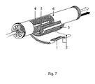
- a permeated liquid flow channel material 1 is sandwiched with separation membranes 2, further a feed flow channel material 3 is disposed on the outer side of the separation membrane 2 to form a set of units; and for the permeation side of the separation membrane to communicate, the unit or a plurality of the unit is wound around a hollow center tube 5 on that water collection holes 4 are arrayed.
- the permeated liquid flow channel material 1 has been using a fabric where a crest and a groove are formed on its surface.
- a fabric where a crest and a groove are formed on the surface conventionally, warp knit fabric such as tricot has generally been used.
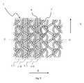
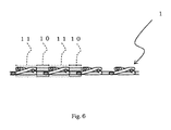
- tricot knit fabric as shown in Fig. 5 (plan view) and Fig. 6 (C-C cross sectional view of Fig. 5 ), in a cross section perpendicular to a knitted loop direction (Y direction in Fig.
- a part that the knitted loop (needle loop 7) is present forms a linear crest 11 and supports the separation membrane, and a region between knitted loops (sinker loop 8) forms a linear groove 10, thereby to produce a flow channel of permeated liquid passed through the separation membrane.
- a pressure is loaded so that a differential pressure of 5 to 10 MPa between the feed side and permeated liquid side is yielded.
- the permeated liquid flow channel material is stiffened.
- a method that an epoxy resin or melamine resin is soaked, or melt-binding that fibers are stiffened by melt each other though heating is commonly known as the stiffening.
- a fabric of the permeated liquid flow channel material is subjected to calendering because a reverse osmosis membrane may be deformed locally or nonuniformly under high pressure.
- the latter method that flow channels are provided on both surfaces of a flow channel material by using a double tricot also poses a problem that the number of units capable of being inserted into a module decreases because the total thickness becomes large, and deteriorating a treatment efficiency. Since tricot cannot narrows the width of a linear crest, it is not possible to increase the number of channels per unit width of a flow channel material. Therefore, the channel width must be widened to reduce the flow channel resistance of permeated liquid; by doing so, there is a problem that a reverse osmosis membrane undergoes a creep deformation with time and falls in.
- An object of the present invention is to provide a liquid separation device preventing a separation membrane from falling in, and having a small flow channel resistance by improving drawbacks of the conventional techniques, narrowing the width of a groove and increasing the number of grooves per unit width of a flow channel material without increasing constituent materials, production processes and the whole thickness.
- the present invention comprises any one of the following constitutions.
- the groove width of a linear groove relative to the pitch of a linear groove can be increased, so the number of grooves per unit width of a flow channel material can be increased without narrowing the groove width.
- the liquid separation device of the present invention comprises a permeated liquid flow channel material disposed on the back side of a separation membrane.
- the permeated liquid flow channel material is characterized in that it is composed of a sheet-like material that a linear groove and a linear crest are alternately arrayed on one surface or both surfaces, a groove width of the linear groove in said sheet-like material is 10 to 200 ⁇ m, and a ratio of the groove width of the linear groove to the pitch of the linear groove is 0.45 or more.
- a groove width of the linear groove in the permeated liquid flow channel material is set to 200 ⁇ m or less to prevent a separation membrane from falling in a linear groove. It is also set to 10 ⁇ m or more to reduce the flow channel resistance. Further, a ratio of the groove width to the pitch of the linear groove of the sheet-like material (hereinafter referred to as groove width/pitch ratio) is 0.45 or more to ensure the cross-sectional area of groove of a flow channel material.
- the upper limit of the groove width/pitch ratio is preferably 0.93 or less in order to suppress the reduction of the separation membrane-supporting area of a linear crest supporting a separation membrane receiving a separation pressure, and to prevent breakage of a linear crest due to concentration of the separation pressure.
- a groove width of a linear groove denotes a distance H shown in Fig. 1 (perspective view schematically showing the flow channel material of the present invention) and Fig. 2 (view schematically showing A-cross section of Fig. 1 ), and a pitch of a linear groove denotes a distance P shown in Figs. 1 and 2 .
- a separation membrane is disposed in the front surface of flow channel material 1 in Fig. 1 , and disposed above a flow channel material 1 in Fig. 2 .
- the permeated liquid flow channel material used in the present invention has the structural features described above; from the points capable of yielding high quality at a low price as well, it is preferable to use a weft knit fabric as shown in Figs. 3 and 4 . Further when a weft knit fabric is used as the permeated liquid flow channel material, to make the groove width/pitch ratio large, respective linear crests repeated are preferably formed by arraying convex parts of yarn loop in a line. Specifically, it can be exemplified by a weft knit fabric with a structure of plain knitting and/or a structure of interlock knitting.
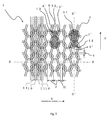
- a linear crest 11 is formed by linking the convex parts of each sinker loop 7 and needle loop 8 in a line in a course direction Y, and a linear groove 10 is formed between said linear crests 11.
- the permeated liquid flow channel material having such groove width and groove width/pitch ratio is also obtained by adopting a weft knit fabric consisting of the needle loop 7 and sinker loop 8, and setting a ratio [S1/(S1+S2) of needle loop area (S1) to the sum of needle loop area (S1) and sinker loop area (S2) to be 0.4 to 0.6. Namely, it is also obtained by setting the needle loop area (S1) and the sinker loop area (S2) to be substantially equal.
- a ratio [S1/(S1+S2)] is preferably set to 0.4 to 0.6.
- a sinker thickness and a needle thickness in a knitting machine may be adjusted.
- a knit structure of a weft knit fabric used as a permeated liquid flow channel material is preferably a structure of plain knitting and/or interlock knitting.
- the needle loop area (S1) and sinker loop area (S2) are measured as follows. First, the surface of a permeated liquid flow channel material is zoomed in a range of 10 to 1000 times from a direction perpendicular to the surface, the enlarged picture obtained is sectionalized by a grid constituted by parallel lines equally dividing by 5 ⁇ m in both course direction Y and wale direction X. Areas of grids containing one loop (needle loop or sinker loop) are summed, which is defined as an area of the loop. By doing other 9 loops consecutive in the wale direction X to the loop in the same manner as described above, an area of each grid is calculated. A value that 10 data obtained are arithmetically averaged is defined as the needle loop area (S1) and sinker loop area (S2) in the present invention.
- the needle loop 7 is a loop formed by a needle in a weft knitting machine;
- the needle loop area (S1) as shown in Fig. 3 , is an area in a range surrounded by an inner boundary line of yarn composing one needle loop 7.
- the edge part of an opening side of a needle loop is a line linking points 12 and 12' present in the farthermost place from the central part of needle loop 7 among intersections of yarn composing one needle loop 7 and yarn composing a needle loop 7' adjacent to the opening side of the needle loop 7. Therefore, the needle loop area (S1) is an area in a range surrounded by a line linking the points 12 and 12' and a yarn composing the needle loop 7.
- the sinker loop 8 is a loop formed by a sinker in a weft knitting machine;
- the sinker loop area (S2) as shown in Fig. 3 , is an area in a range surrounded by an inner boundary line of yarn composing one sinker loop 8.
- the edge part of an opening side of a sinker loop is a line linking points 13 and 13' present in the farthermost place from the central part of sinker loop 8 among intersections of yarn composing one sinker loop 8 and yarn composing a sinker loop 8' adjacent to the opening side of the sinker loop 8. Therefore, the sinker loop area (S2) is an area in a range surrounded by a line linking the points 13 and 13' and a yarn composing the sinker loop 8
- the groove width H of a linear groove is represented by a length in the wale direction X of a void part between yarns in the narrowest part of each opening of needle loop and sinker loop. Specifically, lengths of void parts between yarns at openings of 10 loops successive in the wale direction X are measured, and by obtaining an arithmetic average of these 10 values, the groove width H can be calculated. On the other hand, as shown in Figs.
- the pitch of a linear groove is represented by a distance between yarns present adjacently at the center part of the course direction Y of loop (place of B-B line in Fig. 3 ). Specifically, distances between 11 yarns (total 10) adjacent in the wale direction X are measured, and by obtaining an arithmetic average of the 10 values obtained, the groove pitch P can be calculated.
- a separation membrane is disposed in the front surface of a flow channel material 1, and in Fig. 4 , it is disposed above a flow channel material 1.
- a weft knit fabric is used as a permeated liquid flow channel material
- a yarn with an outer diameter of 244 ⁇ m or less is preferable.
- a yarn with an outer diameter of 15 ⁇ m or more is preferable.
- a groove width of the linear groove is 10 to 200 ⁇ m, and a ratio of the groove width of the linear groove to the pitch of the linear groove is 0.45 or more.
- the outer diameters of 10 yarns adjacent each other in the course direction Y at the center part of the wale direction X of loop are measured, and the outer diameter, d of a yarn is an arithmetic average of the 10 values obtained
- a fiber material composing a weft knit fabric may be any one as long as it maintains a shape as a permeated liquid flow channel material and it has few component solving into a permeating liquid; for example, there are listed organic fibers including polyamide fibers such as nylon 6 and nylon 66, polyester fibers, polyacrylic fibers, polyolefin fibers such as polyethylene and polypropylene, polyvinylchloride fiber, polyvinylidene chloride fiber, polyfluoroethylene fiber and carbon fiber.
- polyester fibers from the considerations of strength sustainable under high pressure and easy processing of a weft knit fabric described later and the like.
- stiffening of the permeated liquid flow channel material is preferably conducted to enhance rigidity.
- a method of stiffening for example, a method that a resin such as melamine resin or epoxy resin is soaked in a woven or knit fabric as a permeated liquid flow channel material can be mentioned.
- melt-binding calendering
- any method can be used as long as it is a treatment method that can obtain hardness yielding no deformation of a flow channel material itself under high pressure.
- calendering may be conducted so that a separation membrane does not undergo a local or nonuniform deformation under high pressure.
- a permeated liquid flow channel material such as a weft knit fabric becomes very smooth and flat since minute undulation derived from a fiber shape is collapsed. Therefore, it becomes possible to further improve performances and durability because a separation membrane does not deform nonuniformly under high pressure.
- a weft knit fabric with a structure of plain knitting and/or a structure of interlock knitting are used as a permeated liquid flow channel material and the permeated liquid flow channel material is subjected to calendering, in knitting the permeated liquid flow channel material, it is preferable that a filament mixed yarn consisting of two or more kinds of filaments having difference in melting points is knitted, then, thermal setting is conducted for calendering at a temperature of the melting point of a lower melting point resin filament or higher and less than the melting point of a higher melting point resin filament composing said filament mixed yarn.
- a permeated liquid flow channel material is knitted with a filament containing a composite yarn that a lower melting point resin is disposed on the outer layer of a higher melting point resin, then, thermal setting is conducted for calendering at a temperature of the melting point of a lower melting point resin or higher and less than the melting point of a higher melting point resin composing said filament.
- the number of units which can be inserted in a module decreases when the thickness is large, which poses a problem of the lowering of treatment capability, so it is preferably 300 ⁇ m or less. It is preferably 30 ⁇ m or more because the cross-sectional area of a groove is small and flow channel resistance increases when the thickness is small.
- a thickness of a sheet-like material T is a distance between the front surface and rear surface in a direction perpendicular to the surface direction as shown in Figs. 2 and 4 , and can be measured by using a micrometer of dial gauge shape with reference to JIS P8118 (1976). Namely, using a micrometer of dial gauge shape having a structure that it has two flat surfaces, a diameter of a smaller surface of the flat surfaces is 14.3 mm, the two surfaces are parallel within 0.
- a sheet-like material is sandwiched by the two surfaces under a constant pressure of 53.9 ⁇ 4.9 kPa, and the thickness can be obtained by reading the scale of at least 0.002 mm in thickness.
- an arithmetic average of the values measured at 10 places is defined as a thickness of a sheet-like material T.
- a depth of a groove in a sheet-like material when the depth is large, the thickness of the sheet-like material becomes inevitably large, and the number of units which can be inserted in a module decreases, which poses a problem of the lowering of treatment capability.
- it is preferably 290 ⁇ m or less. It is preferably 15 ⁇ m or more because the cross-sectional area of a groove is small and the flow channel resistance increases when the depth is small.
- a depth of a groove D is a distance from a part protruding most on the surface to the bottom of a groove as shown in Figs. 2 and 4 ; in the case of a weft knit fabric shown in Fig. 4 , it is equal to a value that the outer diameter of a yarn is subtracted from a thickness of a sheet-like material T.
- a separation membrane includes a reverse osmosis membrane, nanofiltration membrane, ultrafiltration membrane and microfiltration membrane, and each can be produced by a known method.
- a separation membrane and a permeated liquid flow channel material are wound around a water collection tube spirally together with a feed flow channel material, thereby to give a liquid separation device.
- the liquid separation device is introduced in a pressure container alone or in plurality thereof, which is used for desalinating sea water or the like in the mode of a separation membrane module.
- a permeated liquid flow channel material was sandwiched by two reverse osmosis membranes of 150 ⁇ m thickness, further, a feed flow channel material was disposed on the outside of the reverse osmosis membranes to give a set of units; by incorporating it in a module of 0.2 m in outer diameter and 1 m in length, a reverse osmosis membrane module was produced.
- sea water having the total dissolved solids of 3.5% by weight was continuously treated for 10 days by giving a pressure difference of 5.5 MPa at a liquid temperature of 25°C, thereby to obtain the volume of permeated water per day and salt rejection factor after 10 days for evaluation.
- the volume of permeated water is a water volume (m 3 /(m 2 .d)) permeating through a unit area (m 2 ) being converted to a unit time (day (d)), and salt rejection factor is expressed by the following formula (1).
- Respective ten reverse osmosis membrane modules were measured, and it was expressed by an arithmetic average thereof.
- Salt rejection factor ( % ) ⁇ 1 - ( salt concentration in permeated liquid ) / ( salt concentration in feed liquid ) ⁇ ⁇ 100
- H groove width
- P pitch
- a thickness of a permeated liquid flow channel material (T) was measured using a micrometer of dial gauge shape having a structure that it had two flat surfaces, a diameter of a smaller surface thereof was 14.3 mm, the two surfaces were parallel within 0.005 mm in accuracy, and the other surface moved in a direction perpendicular to said flat surface.
- a sheet-like material was sandwiched by the two surfaces of the micrometer under a constant pressure 53.9 ⁇ 4.9 kPa, and the thickness was read to at least 0.002 mm in thickness. Ten places were measured, and it was expressed by an arithmetic average thereof.
- a depth of a groove (D) in a permeated liquid flow channel material was expressed by a value that the outer diameter of a yarn (d) was subtracted from the thickness of a permeated liquid flow channel material (T).
- T thickness of a permeated liquid flow channel material
- ten yarns next to each other in a course direction Y were measured for the outer diameters at the center part of a wale direction X of loop (place of B'-B' line in Fig. 3 ), and it was expressed by an arithmetic average thereof.
- a permeated liquid flow channel material 1 was sandwiched with two reverse osmosis membranes 2 of 150 ⁇ m consisting of an aromatic polyamide membrane 17 (thickness of 0.2 ⁇ m), a porous polysulfone support membrane 16 (thickness of 49.8 ⁇ m) and a non-woven 15 (base weight of 85 g/m 2 , thickness of 100 ⁇ m) composed mainly of polyethylene terephthalate fiber.
- a reverse osmosis membrane module was produced as described in the measurement technique; when sea water of the total dissolved solids of 3.5% by weight was treated with the module by giving a pressure difference of 5.5 MPa at a liquid temperature of 25°C, the case that the volume of permeated water is 22 m 3 /day or more was determined as "good", and the case that the volume of permeated water is less than 22 m 3 /day was determined as "bad.”
- a multi-filament yarn (48 filaments, 110 dtex) that a polyethylene terephthalate filament (melting point: 255°C) was mixed with a polyethylene terephthalate-type lower melting point filament (melting point: 235°C) was used as a knitting yarn; a weft knit structure of a plain knitting (gauge (the number of needles per unit length in a knitting machine) 32) was knitted, which was subjected to thermal setting at 245°C, then to calendering, thereby to produce a permeated liquid flow channel material that the groove width was 130 ⁇ m, a ratio of the groove width to the pitch of a linear groove was 0.52, the depth of a linear groove was 110 ⁇ m, the thickness was 220 ⁇ m and a ratio [S1/(S1+S2)] of needle loop area (S1) to the sum of needle loop area (S1) and sinker loop area (S2) was 0.48.
- Evaluations were conducted by the same simulation technique as in Example 1 except for using a permeated liquid flow channel material that the groove width was 80 ⁇ m, a ratio of the groove width to the pitch of a linear groove was 0.50, the depth of a linear groove was 80 ⁇ m and the thickness was 170 ⁇ m. As a result, the liquidity of permeated liquid was good, and there was no damage in both membrane and permeated liquid flow channel material.
- Evaluations were conducted by the same simulation technique as in Example 1 except for using a permeated liquid flow channel material that the groove width was 192 ⁇ m, a ratio of the groove width to the pitch of a linear groove was 0.90, the depth of a linear groove was 21 ⁇ m and the thickness was 50 ⁇ m. As a result, the liquidity of permeated liquid was good, and there was no damage in both membrane and permeated liquid flow channel material.
- Evaluations were conducted by the same simulation technique as in Example 1 except for using a permeated liquid flow channel material that the groove width was 170 ⁇ m, a ratio of the groove width to the pitch of a linear groove was 0.68, the depth of a linear groove was 80 ⁇ m and the thickness was 170 ⁇ m. As a result, the liquidity of permeated liquid was good, and there was no damage in both membrane and permeated liquid flow channel material.
- a multi-filament yarn 48 filaments, 155 dtex
- a polyethylene terephthalate filament (melting point: 255°C) was mixed with a polyethylene terephthalate-type lower melting point filament (melting point: 235°C)
- a knitting yarn it was knitted into a tricot fabric (structure of double denbigh, gauge 28), which was subjected to thermal setting at 245°C, then to calendering, thereby to produce a permeated liquid flow channel material that the groove width was 254 ⁇ m, a ratio of the groove width to the pitch of a linear groove was 0.43, the depth of a linear groove was 110 ⁇ m, the thickness was 220 ⁇ m and a ratio [S1/(S1+S2)] of needle loop area (S1) to the sum of needle loop area (S1) and sinker loop area (S2) was 0.38.
- the groove width became large because it was a tricot fabric with a small gauge compared with Example 1, and the width of crest became wide because of thick yarn and tricot knitting, and a ratio of the groove width to the pitch of a groove became small. Since the sinker loop area (S2) was large compared to the needle loop area (S1), the groove width of the linear groove of sinker loop became wider than the groove width of the linear groove of needle loop.
- Example 2 Evaluations were conducted by the same measurement technique as in Example 1. As a result, the volume of permeated water was 20 m 3 /day and salt rejection factor was 99.70%. Since the groove width of a linear groove in the permeated liquid flow channel material was wide, the reverse osmosis membrane fell in markedly. As a result, in comparison with Example 1, the flow channel resistance of permeated liquid became large, and the volume of permeated water decreased. Further, a large tensile force was generated on the surface of the reverse osmosis membrane, breakage was locally generated, the function of the reverse osmosis membrane deteriorated and salt rejection factor deteriorated.
- the same multi-filament yarn (48 filaments, 110 dtex) as in Example 1 was used as a knitting yarn; it was knitted into a tricot fabric (structure of double denbigh, gauge 32), which was subjected to thermal setting at 245°C, then to calendering, thereby to produce a permeated liquid flow channel material that the groove width was 254 ⁇ m, a ratio of the groove width to the pitch of a linear groove was 0.52, the depth of a linear groove was 110 ⁇ m, the thickness was 220 ⁇ m and a ratio [S1/(S1+S2)] of needle loop area (S1) to the sum of needle loop area (S1) and sinker loop area (S2) was 0. 63. Since the needle loop area (S2) was large compared with the sinker loop area (S1), the groove width of the linear groove of needle loop became wider than that of sinker loop.
- This permeated liquid flow channel material was the one using a tricot fabric knitted with the same yarn and the same gauge number as in Example 1, but the crest width of a linear crest became wide and the groove width also became wide because of tricot knitting.
- the same multi-filament yarn (48 filaments, 155 dtex) as in Comparative example 1 was used as a knitting yarn; it was knitted into a weft knit structure of plain knitting (gauge 28), which was subjected to thermal setting at 245°C, then to calendering, thereby to produce a permeated liquid flow channel material that the groove width was 130 ⁇ m, a ratio of the groove width to the pitch of a linear groove was 0.43, the depth of a linear groove was 110 ⁇ m, the thickness was 220 and a ratio [S1/(S1+S2)] of needle loop area (S1) to the sum of needle loop area (S1) and sinker loop area (S2) was 0.20.
- This flow channel material was the one using a plain fabric in the same manner as in Example 1, but the yarn was thick and the gauge number was small compared with Example 1, so the crest width of a linear crest became wide, and a ratio of the groove width to the pitch of a linear groove became small. The difference between the needle loop area (S1) and sinker loop area (S2) became large.
- Evaluations were conducted by the same simulation technique as in Example 1 except for using a permeated liquid flow channel material that the groove width was 8 ⁇ m, a ratio of the groove width to the pitch of a linear groove was 0.45, the depth of a linear groove was 10 ⁇ m, the thickness was 23 ⁇ m and a ratio [S1/(S1+S2)] of needle loop area (S1) to the sum of needle loop area (S1) and sinker loop area (S2) was 0.61.
- S1/(S1+S2)] of needle loop area (S1) to the sum of needle loop area (S1) and sinker loop area (S2) was 0.61.
- the groove width was narrow, and the difference between the sinker loop area and needle loop area was large; as a result, the flow channel resistance became large and the liquidity of permeated liquid deteriorated.
- Evaluations were conducted by the same simulation technique as in Example 1 except for using a permeated liquid flow channel material that the groove width was 120 ⁇ m, a ratio of the groove width to the pitch of a linear groove was 0.95, the depth of a linear groove was 6 ⁇ m, the thickness was 17 ⁇ m and a ratio [S1/(S1+S2)] of needle loop area (S1) to the sum of needle loop area (S1) and sinker loop area (S2) was 0.38. As a result, the liquidity of permeated liquid was good, and no breakage of the membrane was observed.
- Example 1 and Comparative examples 1 to 3 are shown all together in Table 1.
- the evaluation conditions and results by simulation techniques in Examples 1 to 5 and Comparative examples 1 to 6 are shown all together in Table 2.
- Shape conditions in Examples 1 to 5 and Comparative examples 1 to 6 are shown all together in Fig. 8 .
- the liquid separation device of the present invention can be suitably used for production of pure water, desalinating sea water and recovery of valuable resources in wastewater treatment and food industries, and the application range is not limited thereto.
Landscapes
- Chemical & Material Sciences (AREA)
- Chemical Kinetics & Catalysis (AREA)
- Engineering & Computer Science (AREA)
- Textile Engineering (AREA)
- Separation Using Semi-Permeable Membranes (AREA)
- Knitting Of Fabric (AREA)
- Treatment Of Fiber Materials (AREA)
- Filtering Materials (AREA)
- Physical Or Chemical Processes And Apparatus (AREA)
Priority Applications (1)
| Application Number | Priority Date | Filing Date | Title |
|---|---|---|---|
| EP20110195040 EP2439321A1 (de) | 2006-03-31 | 2007-03-23 | Flüssigkeitstrennungsvorrichtung, Strömungskanalmaterial und Herstellungsverfahren dafür |
Applications Claiming Priority (2)
| Application Number | Priority Date | Filing Date | Title |
|---|---|---|---|
| JP2006097161 | 2006-03-31 | ||
| PCT/JP2007/055944 WO2007114069A1 (ja) | 2006-03-31 | 2007-03-23 | 液体分離素子、流路材およびその製造方法 |
Publications (2)
| Publication Number | Publication Date |
|---|---|
| EP2002880A1 true EP2002880A1 (de) | 2008-12-17 |
| EP2002880A4 EP2002880A4 (de) | 2011-06-22 |
Family
ID=38563338
Family Applications (2)
| Application Number | Title | Priority Date | Filing Date |
|---|---|---|---|
| EP20110195040 Withdrawn EP2439321A1 (de) | 2006-03-31 | 2007-03-23 | Flüssigkeitstrennungsvorrichtung, Strömungskanalmaterial und Herstellungsverfahren dafür |
| EP07739385A Withdrawn EP2002880A4 (de) | 2006-03-31 | 2007-03-23 | Flüssigkeitstrennvorrichtung, strömungskanalmaterial und herstellungsverfahren dafür |
Family Applications Before (1)
| Application Number | Title | Priority Date | Filing Date |
|---|---|---|---|
| EP20110195040 Withdrawn EP2439321A1 (de) | 2006-03-31 | 2007-03-23 | Flüssigkeitstrennungsvorrichtung, Strömungskanalmaterial und Herstellungsverfahren dafür |
Country Status (7)
| Country | Link |
|---|---|
| US (1) | US8388848B2 (de) |
| EP (2) | EP2439321A1 (de) |
| JP (1) | JP5186921B2 (de) |
| KR (1) | KR101353830B1 (de) |
| CN (2) | CN102068908B (de) |
| TW (1) | TW200744743A (de) |
| WO (1) | WO2007114069A1 (de) |
Cited By (6)
| Publication number | Priority date | Publication date | Assignee | Title |
|---|---|---|---|---|
| WO2013058921A1 (en) * | 2011-10-19 | 2013-04-25 | General Electric Company | Spiral wound membrane element and permeate carrier |
| CN103842055A (zh) * | 2011-09-29 | 2014-06-04 | 东丽株式会社 | 分离膜、分离膜元件及分离膜的制造方法 |
| EP2735357A4 (de) * | 2011-09-29 | 2014-12-10 | Toray Industries | Trennmembran und trennmembranelement |
| EP2730331A4 (de) * | 2011-07-07 | 2014-12-10 | Toray Industries | Trennmembran, trennmembranenelement und verfahren zur herstellung der trennmembran |
| EP3199225A4 (de) * | 2014-09-25 | 2018-06-27 | Nitto Denko Corporation | Spiralförmiges membranelement |
| US10583400B2 (en) | 2011-10-19 | 2020-03-10 | Bl Technologies, Inc. | Material efficiency and fabrication of membrane elements |
Families Citing this family (38)
| Publication number | Priority date | Publication date | Assignee | Title |
|---|---|---|---|---|
| US8661648B2 (en) * | 2010-03-24 | 2014-03-04 | Dow Global Technologies Llc | Spiral wound filtration module |
| CN103068472B (zh) | 2010-10-26 | 2015-04-29 | 陶氏环球技术有限责任公司 | 包括具不同渗透率区域的膜片的螺旋卷组件 |
| CN103596666A (zh) * | 2011-04-13 | 2014-02-19 | Gfd纺织公司 | 用于流体过滤系统的过滤元件 |
| WO2013130312A1 (en) | 2012-03-02 | 2013-09-06 | Dow Global Technologies Llc | Multi-pass hyperfiltration system |
| US10350529B2 (en) | 2012-06-21 | 2019-07-16 | Entegris, Inc. | Filtration article with fluoropolymer knit |
| JP6179403B2 (ja) * | 2012-06-28 | 2017-08-16 | 東レ株式会社 | 分離膜および分離膜エレメント |
| JP2015529552A (ja) * | 2012-07-23 | 2015-10-08 | ダブリュ.エル.ゴア アンド アソシエイツ,インコーポレイティドW.L. Gore & Associates, Incorporated | フルオロポリマーニットを有する濾過物品 |
| CN104470624A (zh) * | 2012-07-31 | 2015-03-25 | 东丽株式会社 | 分离膜及分离膜元件 |
| EP2892636A4 (de) * | 2012-09-06 | 2016-07-20 | Smartflow Technologies Inc | Permeatkanaländerungen für eine gegenstromfilterung zur verwendung in querströmungs-filterungsmodulen für osmosesysteme |
| KR102077361B1 (ko) * | 2012-11-27 | 2020-02-13 | 도레이 카부시키가이샤 | 분리막 모듈 |
| EP2958665B1 (de) | 2013-04-26 | 2018-07-04 | Dow Global Technologies LLC | Anordnung mit seriell verbundenen spiralwickelmodulen mit permeatdurchflussregler |
| JP2015085233A (ja) * | 2013-10-29 | 2015-05-07 | 日東電工株式会社 | 流路部材及び正浸透膜エレメント |
| JP2015085234A (ja) * | 2013-10-29 | 2015-05-07 | 日東電工株式会社 | 正浸透膜エレメント |
| US10258928B2 (en) | 2014-03-31 | 2019-04-16 | Dow Global Technologies Llc | Spiral wound membrane module adapted for high recovery |
| US9725344B1 (en) | 2014-09-24 | 2017-08-08 | Dow Global Technologies Llc | Spiral wound filtration assembly including integral bioreactor |
| JP6637232B2 (ja) * | 2014-11-13 | 2020-01-29 | 日東電工株式会社 | スパイラル型膜エレメント用透過側流路材、及びその製造方法 |
| CN107106997B (zh) * | 2014-11-20 | 2021-10-26 | 恩特格里斯公司 | 接枝的超高分子量聚乙烯微孔膜 |
| JP6634828B2 (ja) * | 2014-12-26 | 2020-01-22 | 東レ株式会社 | 分離膜エレメント |
| AU2016218454A1 (en) | 2015-02-11 | 2017-09-14 | Dow Global Technologies Llc. | Submerged hyperfiltration system |
| US10010833B2 (en) | 2015-02-18 | 2018-07-03 | Lg Nanoh2O, Inc. | Spiral wound membrane module with reinforced fold line |
| CN107531526B (zh) | 2015-04-16 | 2021-04-06 | 陶氏环球技术有限责任公司 | 包含螺旋卷绕生物反应器和超滤膜模块的过滤总成 |
| US10335737B2 (en) | 2015-04-16 | 2019-07-02 | Dow Global Technologies Llc | Filtration assembly including spiral wound bioreactors and membrane modules positioned in separate pressure vessels |
| EP3328524B8 (de) | 2015-07-29 | 2020-03-04 | DDP Specialty Electronic Materials US, Inc. | Filteranordnung mit spiralförmig gewickeltem membranmodul und laugendichtung |
| US10252473B2 (en) | 2015-08-31 | 2019-04-09 | Lg Nanoh2O, Inc. | Compression bar apparatus |
| JP6609042B2 (ja) | 2015-09-30 | 2019-11-20 | ダウ グローバル テクノロジーズ エルエルシー | 螺旋巻きモジュール、塩水シール、及び端キャップを含むフィルタアセンブリ |
| JP6347775B2 (ja) * | 2015-12-28 | 2018-06-27 | 日東電工株式会社 | スパイラル型膜エレメント |
| KR20180103119A (ko) * | 2016-01-29 | 2018-09-18 | 도레이 카부시키가이샤 | 유로재 |
| KR20180103926A (ko) * | 2016-01-29 | 2018-09-19 | 도레이 카부시키가이샤 | 분리막 엘리먼트 |
| JP6308331B2 (ja) * | 2016-04-27 | 2018-04-11 | 東レ株式会社 | 分離膜エレメント |
| MX2019002365A (es) | 2016-08-31 | 2019-06-24 | Dow Global Technologies Llc | Montaje de modulo enrollado en espiral que incluye monitoreo de permeado integrado. |
| JP7037306B2 (ja) | 2016-09-16 | 2022-03-16 | 日東電工株式会社 | スパイラル型膜エレメント |
| JP7121036B2 (ja) | 2017-04-05 | 2022-08-17 | ダウ グローバル テクノロジーズ エルエルシー | 統合圧力モニタリングを含むスパイラル巻きモジュールアセンブリ |
| EP3658261B1 (de) | 2017-07-27 | 2021-08-04 | DDP Specialty Electronic Materials US, LLC | Spiralförmig gewickeltes membranmodul mit integrierter differenzdrucküberwachung |
| JP7540944B2 (ja) | 2018-01-15 | 2024-08-27 | ディディピー スペシャルティ エレクトロニック マテリアルズ ユーエス,エルエルシー | 流量制限器及びセンサが組み込まれたスパイラル型アセンブリ |
| CN109012205B (zh) * | 2018-08-23 | 2020-11-13 | 山东九章膜技术有限公司 | 一种产水隔网、卷制方法以及反渗透膜元件 |
| JP6759490B1 (ja) * | 2019-02-01 | 2020-09-23 | 旭化成株式会社 | 緯編地 |
| CN119365644A (zh) * | 2022-09-23 | 2025-01-24 | 东丽纤维研究所(中国)有限公司 | 针织面料及其应用和生理用品 |
| US20240126008A1 (en) * | 2022-10-06 | 2024-04-18 | Paul K. Westerhoff | Composite material with side-emitting optical fibers |
Family Cites Families (20)
| Publication number | Priority date | Publication date | Assignee | Title |
|---|---|---|---|---|
| JPS5431087A (en) * | 1977-08-11 | 1979-03-07 | Toray Ind Inc | Separating apparatus for liquid |
| US4183993A (en) * | 1978-01-30 | 1980-01-15 | Gulf States Paper Corporation | Reinforced fabric and laminate made therewith |
| JPH0692270B2 (ja) | 1985-08-15 | 1994-11-16 | 株式会社日立製作所 | 窒化珪素焼結体 |
| GB8522847D0 (en) * | 1985-09-16 | 1985-10-23 | Shell Int Research | Supported membrane |
| GB8928050D0 (en) * | 1989-12-12 | 1990-02-14 | Anand Subhash C | Improvements in or relating to textile filter sleeves |
| US5275725A (en) * | 1990-11-30 | 1994-01-04 | Daicel Chemical Industries, Ltd. | Flat separation membrane leaf and rotary separation apparatus containing flat membranes |
| DE4310110A1 (de) * | 1992-07-07 | 1994-01-13 | Kaercher Gmbh & Co Alfred | Mehrlagiges, textiles, gasdurchlässiges Filtermaterial gegen chemische Schadstoffe |
| JPH09141060A (ja) * | 1995-11-21 | 1997-06-03 | Toray Ind Inc | 液体分離素子、装置、及び処理方法 |
| JP3430783B2 (ja) * | 1996-04-11 | 2003-07-28 | 東レ株式会社 | 液体分離素子、装置および処理方法 |
| US6250060B1 (en) * | 1997-04-18 | 2001-06-26 | Wellman, Inc. | Method of producing improved knit fabrics from blended fibers |
| DE69927312T2 (de) * | 1998-03-20 | 2006-05-11 | Toray Industries, Inc. | Trennelemente für Fluide |
| JP3559475B2 (ja) * | 1999-06-15 | 2004-09-02 | 日東電工株式会社 | 液体分離膜モジュール |
| JP3956262B2 (ja) | 1999-06-08 | 2007-08-08 | 日東電工株式会社 | 液体分離膜モジュール |
| EP1059114B1 (de) | 1999-06-08 | 2005-10-12 | Nitto Denko Corporation | Membranmodul zur Trennung von Flüssigkeiten und Verfahren zu seiner Herstellung |
| US6986428B2 (en) * | 2003-05-14 | 2006-01-17 | 3M Innovative Properties Company | Fluid separation membrane module |
| KR100586733B1 (ko) * | 2004-07-29 | 2006-06-08 | 주식회사 새 한 | 나권형 분리막 모듈 제조방법 |
| EP1625885A1 (de) * | 2004-08-11 | 2006-02-15 | Vlaamse Instelling Voor Technologisch Onderzoek (Vito) | Membran mit integriertem Permeatkanal |
| US20070095756A1 (en) * | 2005-10-31 | 2007-05-03 | General Electric Company | System and method for removal of contaminants from feed solution |
| EP1992400A1 (de) * | 2007-05-18 | 2008-11-19 | Vlaamse Instelling Voor Technologisch Onderzoek (Vito) | Membranbeutel und Verfahren zu dessen Herstellung |
| DE102008036098B4 (de) * | 2008-08-04 | 2016-04-28 | Mn-Beteiligungs-Gmbh | Filtermodul mit spiralförmig gewickelten Flachfiltern, Verfahren zu dessen Herstellung und daraus aufgebautes Filtrationssystem |
-
2007
- 2007-03-23 CN CN2010105937811A patent/CN102068908B/zh not_active Expired - Fee Related
- 2007-03-23 KR KR1020087026441A patent/KR101353830B1/ko not_active Expired - Fee Related
- 2007-03-23 EP EP20110195040 patent/EP2439321A1/de not_active Withdrawn
- 2007-03-23 EP EP07739385A patent/EP2002880A4/de not_active Withdrawn
- 2007-03-23 WO PCT/JP2007/055944 patent/WO2007114069A1/ja not_active Ceased
- 2007-03-23 JP JP2007513572A patent/JP5186921B2/ja not_active Expired - Fee Related
- 2007-03-23 CN CN2007800094793A patent/CN101405072B/zh not_active Expired - Fee Related
- 2007-03-29 TW TW096110963A patent/TW200744743A/zh unknown
- 2007-03-31 US US12/295,133 patent/US8388848B2/en not_active Expired - Fee Related
Cited By (10)
| Publication number | Priority date | Publication date | Assignee | Title |
|---|---|---|---|---|
| EP2730331A4 (de) * | 2011-07-07 | 2014-12-10 | Toray Industries | Trennmembran, trennmembranenelement und verfahren zur herstellung der trennmembran |
| US9616390B2 (en) | 2011-07-07 | 2017-04-11 | Toray Industries, Inc. | Separation membrane, separation membrane element, and method for producing separation membrane |
| CN103842055A (zh) * | 2011-09-29 | 2014-06-04 | 东丽株式会社 | 分离膜、分离膜元件及分离膜的制造方法 |
| EP2742992A4 (de) * | 2011-09-29 | 2014-12-10 | Toray Industries | Trennmembran, trennmembranenelement und verfahren zur herstellung der trennmembran |
| EP2735357A4 (de) * | 2011-09-29 | 2014-12-10 | Toray Industries | Trennmembran und trennmembranelement |
| CN103842055B (zh) * | 2011-09-29 | 2016-08-17 | 东丽株式会社 | 分离膜、分离膜元件及分离膜的制造方法 |
| WO2013058921A1 (en) * | 2011-10-19 | 2013-04-25 | General Electric Company | Spiral wound membrane element and permeate carrier |
| US10583400B2 (en) | 2011-10-19 | 2020-03-10 | Bl Technologies, Inc. | Material efficiency and fabrication of membrane elements |
| EP3199225A4 (de) * | 2014-09-25 | 2018-06-27 | Nitto Denko Corporation | Spiralförmiges membranelement |
| US10918996B2 (en) | 2014-09-25 | 2021-02-16 | Nitto Denko Corporation | Spiral membrane element |
Also Published As
| Publication number | Publication date |
|---|---|
| TW200744743A (en) | 2007-12-16 |
| KR20090009216A (ko) | 2009-01-22 |
| WO2007114069A1 (ja) | 2007-10-11 |
| CN102068908B (zh) | 2013-03-27 |
| EP2002880A4 (de) | 2011-06-22 |
| US8388848B2 (en) | 2013-03-05 |
| CN102068908A (zh) | 2011-05-25 |
| JP5186921B2 (ja) | 2013-04-24 |
| EP2439321A1 (de) | 2012-04-11 |
| JPWO2007114069A1 (ja) | 2009-08-13 |
| CN101405072A (zh) | 2009-04-08 |
| US20100006504A1 (en) | 2010-01-14 |
| CN101405072B (zh) | 2012-01-11 |
| KR101353830B1 (ko) | 2014-01-21 |
Similar Documents
| Publication | Publication Date | Title |
|---|---|---|
| US8388848B2 (en) | Liquid separation device, flow channel material and process for producing the same | |
| EP2152394B1 (de) | Membranbeutel mit nahtloser membransubstanz, verwendung dafür und filtriereinheiten damit | |
| JPH09276671A (ja) | 液体分離素子、装置および処理方法 | |
| KR100846647B1 (ko) | 스파이럴형 분리막 엘리먼트 | |
| JP6844533B2 (ja) | 流路材 | |
| JP6575154B2 (ja) | トリコット流路材 | |
| CN102811799B (zh) | 用于过滤装置的隔片 | |
| JP2006247453A (ja) | 液体分離素子、およびそれを用いた逆浸透装置、逆浸透膜処理方法 | |
| KR20220052935A (ko) | 분리막 엘리먼트 | |
| EP3051014A1 (de) | Vliesstoff, trennmembranträger, trennmembran, fluidtrennungselement und verfahren zur herstellung des vliesstoffs | |
| WO2009135529A1 (en) | Membrane bags with seamless membrane substance, uses thereof, filtration units therewith and manufacturing processes. | |
| KR20190032386A (ko) | 분리막 엘리먼트 | |
| US9636637B2 (en) | Permeate carrier fabric for membrane filters | |
| KR101647909B1 (ko) | 막 필터용 투과액 캐리어 직물 | |
| JPH09141060A (ja) | 液体分離素子、装置、及び処理方法 | |
| JP3317113B2 (ja) | 液体分離素子、装置、および処理方法 | |
| JP7358914B2 (ja) | 流路材 | |
| JP2016221505A (ja) | 分離膜エレメント | |
| JPH0747112B2 (ja) | スパイラル型液体分離素子 | |
| JP2024021795A (ja) | Ro用流路材 | |
| WO2013188089A1 (en) | Permeate carrier fabric for membrane filters | |
| WO2023281719A1 (ja) | 液体分離装置用流路材 | |
| JP2000051667A (ja) | 液体分離素子および造水方法 |
Legal Events
| Date | Code | Title | Description |
|---|---|---|---|
| PUAI | Public reference made under article 153(3) epc to a published international application that has entered the european phase |
Free format text: ORIGINAL CODE: 0009012 |
|
| 17P | Request for examination filed |
Effective date: 20080919 |
|
| AK | Designated contracting states |
Kind code of ref document: A1 Designated state(s): AT BE BG CH CY CZ DE DK EE ES FI FR GB GR HU IE IS IT LI LT LU LV MC MT NL PL PT RO SE SI SK TR |
|
| A4 | Supplementary search report drawn up and despatched |
Effective date: 20110520 |
|
| DAX | Request for extension of the european patent (deleted) | ||
| 17Q | First examination report despatched |
Effective date: 20120222 |
|
| STAA | Information on the status of an ep patent application or granted ep patent |
Free format text: STATUS: THE APPLICATION IS DEEMED TO BE WITHDRAWN |
|
| 18D | Application deemed to be withdrawn |
Effective date: 20131001 |