EP2002912A2 - Auslegertisch für eine Format- bzw. Plattensäge - Google Patents
Auslegertisch für eine Format- bzw. Plattensäge Download PDFInfo
- Publication number
- EP2002912A2 EP2002912A2 EP08010416A EP08010416A EP2002912A2 EP 2002912 A2 EP2002912 A2 EP 2002912A2 EP 08010416 A EP08010416 A EP 08010416A EP 08010416 A EP08010416 A EP 08010416A EP 2002912 A2 EP2002912 A2 EP 2002912A2
- Authority
- EP
- European Patent Office
- Prior art keywords
- stop
- boom
- boom table
- base element
- table according
- Prior art date
- Legal status (The legal status is an assumption and is not a legal conclusion. Google has not performed a legal analysis and makes no representation as to the accuracy of the status listed.)
- Granted
Links
Images

Classifications
-
- B—PERFORMING OPERATIONS; TRANSPORTING
- B27—WORKING OR PRESERVING WOOD OR SIMILAR MATERIAL; NAILING OR STAPLING MACHINES IN GENERAL
- B27B—SAWS FOR WOOD OR SIMILAR MATERIAL; COMPONENTS OR ACCESSORIES THEREFOR
- B27B27/00—Guide fences or stops for timber in saw mills or sawing machines; Measuring equipment thereon
- B27B27/08—Guide fences or stops for timber in saw mills or sawing machines; Measuring equipment thereon arranged adjustably, not limited to only one of the groups B27B27/02 - B27B27/06
-
- B—PERFORMING OPERATIONS; TRANSPORTING
- B23—MACHINE TOOLS; METAL-WORKING NOT OTHERWISE PROVIDED FOR
- B23D—PLANING; SLOTTING; SHEARING; BROACHING; SAWING; FILING; SCRAPING; LIKE OPERATIONS FOR WORKING METAL BY REMOVING MATERIAL, NOT OTHERWISE PROVIDED FOR
- B23D47/00—Sawing machines or sawing devices working with circular saw blades, characterised only by constructional features of particular parts
- B23D47/02—Sawing machines or sawing devices working with circular saw blades, characterised only by constructional features of particular parts of frames; of guiding arrangements for work-table or saw-carrier
- B23D47/025—Sawing machines or sawing devices working with circular saw blades, characterised only by constructional features of particular parts of frames; of guiding arrangements for work-table or saw-carrier of tables
-
- B—PERFORMING OPERATIONS; TRANSPORTING
- B27—WORKING OR PRESERVING WOOD OR SIMILAR MATERIAL; NAILING OR STAPLING MACHINES IN GENERAL
- B27B—SAWS FOR WOOD OR SIMILAR MATERIAL; COMPONENTS OR ACCESSORIES THEREFOR
- B27B27/00—Guide fences or stops for timber in saw mills or sawing machines; Measuring equipment thereon
- B27B27/10—Devices for moving or adjusting the guide fences or stops
Definitions
- the present invention relates to an outrigger table for a format or panel saw, on which a stop for the workpiece to be machined is arranged or can be arranged, wherein the stop is pivotable about a relative to the boom table, in particular stationary axis of rotation relative to the saw blade and on a base element, which is connected relative to the boom table slidably connected to this, is fixable in position.
- the jib table of a sizing table saw represents a lateral extension of the saw table surface and serves as a support for the workpiece to be machined, wherein the support surface of the jib table lies in the same plane as the saw table and the jib table in the longitudinal direction of the saw plate parallel to the saw table slidably disposed on this.
- this object is achieved by the support surface of the base element is arranged in the plane of the support surface of the delivery table.
- the stop is coupled to the base element and fixed in position, in particular fixed rotatable, the base element moves with a pivoting of the stop, so that the support surface of the base member for the workpiece remains substantially equal even with pivoted stop, without the frame of the boom table must be changed, whereby a stable and accurate guidance of the boom table over the saw table is guaranteed.
- the support surface of the base member is arranged in the plane of the support surface of the delivery table, an exact guidance of the workpiece and thus a clean cross-sectional image is achieved.
- a structurally simple and user-friendly solution for the user is achieved according to a further embodiment, when the base member is slidably disposed in the direction of displacement of the boom table on this.
- a preferred embodiment of the invention provides that the base member by means of a locking mechanism relative to the boom table is fixed in position, with a structurally simple solution is achieved when the Locking mechanism is formed by a preferably actuated by means of a pivoting lever clamping device.
- the fixation of the stop relative to the delivery table by means of a slidably mounted on the underside of the stop in the longitudinal direction of the guide element, which engages in a receiving element formed on the base member takes place, wherein a structurally simple solution is then achieved ,
- the guide element is slidably mounted and fixed in position in a arranged on the underside of the stop preferably groove-shaped elongated guide, wherein it has been found to be particularly favorable when the receiving opening on Base element for positionally fixable receiving formed on the stop guide element formed.
- An alternative embodiment of the invention provides that the fixation of the stop relative to the delivery table by means of a arranged on the base element guide pin which engages in at least one formed on the underside of the stop receiving opening takes place.
- the receiving opening is formed on the underside of the stop by a preferably groove-shaped, elongated guide which extends in the longitudinal direction of the stop and is formed for displaceable and positionally fixable receiving the formed on the base member guide pin
- a second embodiment provides that a plurality of spaced apart in the longitudinal direction of the stop receiving openings, preferably blind holes, are formed on the underside of the stop.
- the scale for adjusting the pivot angle for the stop can be arranged on the saw table, a preferred embodiment of the invention provides for arranging this scale on the displaceable base element or on the lay-out table.
- the invention relates to a format or panel saw with a boom table according to the invention.
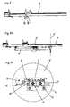
- Fig. 1a and 1b is a plan view of a section of a format or panel saw 1, in which a boom table 4 is arranged relative to the saw table 2 slidably, wherein the sliding direction R is parallel to the longitudinal direction of the saw blade 3.
- a stop 6, also called Ablfitanschlag mounted in which the workpiece, not shown, is struck for cutting.
- the stop 6 is pivotable about the pivot angle ⁇ relative to the saw blade 3, wherein the pivot angle ⁇ in the Fig. 1a 90 ° and in the Fig. 1b 45 °.
- the fulcrum of the stop 6 is in the embodiment shown mounted on a mounting rail 14 which is attachable to the boom table 4, so that the stop about the axis of rotation a ( Fig. 2a ) can be pivoted relative to the boom table 4.
- the second receiving point for the stop 6 on the delivery table 4 is mounted on the displaceable base element 5, so that a change in the pivot angle ⁇ can be achieved both by pivoting the stop 6 and by a displacement of the base element 5.
- Fig. 1b How out Fig. 1b can be seen is achieved by the invention that the located in front of the stop 6 support surface F of the movable base member 5 in both illustrated positions of the stop 6 is substantially equal.
- Fig. 2 the stop 6 is shown in a side view.
- a jaw 15 is slidably mounted with the guide member 9 in a groove.
- the position fixation of the stop 6 relative to the displaceable base element 5 thus takes place via the clamping jaws 15, which can be actuated by means of a pivoting lever 16.
- the definition of the displaceable base element relative to the boom table 4, wherein the corresponding locking mechanism 7 via the pivot lever 8 is actuated ( Fig. 1 b) ,
- Fig. 2a and 2b the arrangement of the stop 6 is shown on the boom table 4, wherein from Fig. 2a the axis of rotation a, by which the stop 6 is pivotable, can be seen.
- Fig. 2b It can be seen that the base member 5 is slidably mounted in two roll cages 11 a linear guide on the boom table 4.
- the determination of the stop 6 relative to the base member 5 also takes place via a clamping device which comprises an actuatable via the pivot lever 16 jaws 15.
- Auslegertica for format or panel saws are of course not to be understood in a limiting sense, but just just individual examples of numerous ways to realize the inventive idea of a boom table with a position fixable on a movable base element stop.
- the leadership of the stop in a slot or even the ability to implement the attack on the opposite side quite conceivable and within the meaning of the invention.
Landscapes
- Life Sciences & Earth Sciences (AREA)
- Engineering & Computer Science (AREA)
- Mechanical Engineering (AREA)
- Wood Science & Technology (AREA)
- Forests & Forestry (AREA)
- Sawing (AREA)
Abstract
Description
- Die vorliegende Erfindung betrifft einen Auslegertisch für eine Format- bzw. Plattensäge, an dem ein Anschlag für das zu bearbeitende Werkstück angeordnet bzw. anordenbar ist, wobei der Anschlag um eine in Bezug auf den Auslegertisch insbesondere ortsfeste Drehachse relativ zum Sägeblatt verschwenkbar und auf bzw. an einem Basiselement, welches relativ zum Auslegertisch verschiebbar mit diesem verbunden ist, lagefixierbar ist.
- Der Auslegertisch einer Format- bzw. Plattensäge stellt eine seitliche Verlängerung der Sägetischfläche dar und dient als Auflage für das zu bearbeitende Werkstück, wobei die Auflagefläche des Auslegertisches in derselben Ebene liegt wie der Sägetisch und der Auslegertisch in der Regel in Längsrichtung des Sägeplattes parallel zum Sägetisch verschiebbar an diesem angeordnet ist.
- Insbesondere bei der Verwendung eines auf dem Auslegertisch anzuordnenden Anschlages für das zu bearbeitende Werkstück ergibt sich bei dem aus der Stand der Technik bekannten Auslegertischen das Problem, dass sich in Folge des Verschwenkens des Anschlages die Auflagefläche des Auslegertisches für das zu bearbeitende Werkstück verkleinert.
- Zur Umgehung dieses Problems ist es bereits bekannt, den Rahmen eines Auslegertisches als Parallelogramm zu verschieben, was neben dem damit verbundenen Mehraufwand auch zu Ungenauigkeiten in Folge der Instabilität eines solchen Auslegerahmens führen kann.
- Ausgehend von diesem Stand der Technik hat es sich die Erfindung zur Aufgabe gemacht, einen Auslegertisch der vorgenannten Art dahingehend zu verbessern, dass die Beibehaltung der Größe der Auflagefläche auch bei Verwendung eines schwenkbaren Anschlages auf einfache Weise möglich ist und der zudem eine exakte Winkeleinstellung bei stabilem Auslegerahmen erlaubt.
- Erfindungsgemäß wird diese Aufgabe gelöst, indem die Auflagefläche des Basiselementes in der Ebene der Auflagefläche des Auslegertisches angeordnet ist.
- Dadurch dass der Anschlag mit dem Basiselement gekoppelt und lagefixierbar, insbesondere ortsfest drehbar, verbunden ist, wandert das Basiselement bei einer Verschwenkung des Anschlages mit, sodass die Auflagefläche des Basiselementes für das Werkstück auch bei verschwenktem Anschlag im Wesentlichen gleich groß bleibt, ohne dass der Rahmen des Auslegertisches verändert werden muss, wodurch eine stabile und exakte Führung des Auslegertisches gegenüber dem Sägetisch gewährleistet bleibt. Dadurch dass, die Auflagefläche des Basiselementes in der Ebene der Auflagefläche des Auslegertisches angeordnet ist, wird eine exakte Führung des Werkstückes und damit ein sauberes Schnittbild erreicht.
- Eine konstruktiv einfache und für den Benutzer bedienerfreundliche Lösung wird gemäß einem weiteren Ausführungsbeispiel dann erreicht, wenn das Basiselement in Verschieberichtung des Auslegertisches verschiebbar an diesem angeordnet ist.
- Grundsätzlich wäre es durchaus denkbar, das Basiselement frei verschiebbar am Auslegertisch zu lagern und die Lagefixierung bei verschwenktem Anschlag ausschließlich über die feste Verbindung des verschwenkten Anschlages mit dem Basiselement sicherzustellen. Im Sinne einer exakten Winkeleinstellung und zur Vermeidung übermäßiger Materialabnutzung im Bereich der Lagerstelle des Anschlages mit dem Basiselement sieht ein bevorzugtes Ausführungsbeispiel der Erfindung vor, dass das Basiselement mittels eines Arretiermechanismus gegenüber dem Auslegertisch lagefixierbar ist, wobei eine konstruktiv einfache Lösung dann erreicht wird, wenn der Arretiermechanismus von einer vorzugsweise mittels eines Schwenkhebel betätigbaren Klemmeinrichtung gebildet ist.
- Gemäß einer weiteren Ausführungsform der Erfindung ist vorgesehen, dass die Fixierung des Anschlages relativ zum Auslegertisch mittels eines auf der Unterseite des Anschlages in Längsrichtung desselben verschiebbar gelagerten Führungselementes, welches in eine am Basiselement ausgebildete Aufnahmeöffnung eingreift, erfolgt, wobei eine konstruktiv einfache Lösung dann erreicht wird, wenn das Führungselement in einer an der Unterseite des Anschlages angeordneten vorzugsweise nutförmigen länglichen Führung verschieb- und lagefixierbar gelagert ist, wobei es sich als besonders günstig herausgestellt hat, wenn die Aufnahmeöffnung am Basiselement zur lagefixierbaren Aufnahme des am Anschlag ausgebildeten Führungselementes ausgebildet.
- Eine alternative Ausführungsform der Erfindung sieht vor, dass die Fixierung des Anschlages relativ zum Auslegertisch mittels eines auf dem Basiselement angeordneten Führungszapfens, der in wenigstens eine an der Unterseite des Anschlages ausgebildete Aufnahmeöffnung eingreift, erfolgt.
- Bei dieser zweiten Ausführungsvariante ist gemäß einem ersten Ausführungsbeispiel vorgesehen, dass die Aufnahmeöffnung auf der Unterseite des Anschlages von einer vorzugsweise nutförmigen, länglichen Führung gebildet ist, die sich in Längsrichtung des Anschlages erstreckt und zur verschieb- und lagefixierbaren Aufnahme des am Basiselement ausgebildeten Führungszapfens ausgebildet ist, während eine zweite Ausführungsform vorsieht, dass auf der Unterseite des Anschlages mehrere in Längsrichtung des Anschlages voneinander beabstandete Aufnahmeöffnungen, vorzugsweise Sackbohrungen, ausgebildet sind.
- Es kommt also im Wesentlichen nicht darauf an, in welchem der beiden Teile, dem Anschlag bzw. dem Basiselement, das Führungselement bzw. die Aufnahmeöffnung ausgebildet ist, vielmehr besteht eine Grundidee der Erfindung darin, das verschiebbare Basiselement mit dem verschwenkbaren Anschlag zu koppeln und diese beiden Teile in einem frei wählbaren Schwenkwinkel gegeneinander zu fixieren.
- Wenn gleich die Skala zum Einstellen des Schwenkwinkels für den Anschlag auch am Sägetisch angeordnet sein kann, sieht ein bevorzugtes Ausführungsbeispiel der Erfindung vor, diese Skala am verschiebbaren Basiselement oder am Auslegetisch anzuordnen.
- Weiters betrifft die Erfindung eine Format- bzw. Plattensäge mit einem erfindungsgemäßen Auslegertisch.
- Weitere Vorteile und Einzelheiten der Erfindung werden in der nachfolgenden Figurenbeschreibung unter Bezugnahme auf die in den Zeichnungen dargestellten Ausführungsbeispielen näher erläutert, Darin zeigt:
- Fig. 1a und b
- schematisch die Anordnung eines Auslegertisches an einem Sägetisch einer Format- bzw. Plattensäge mit einem Anschlag in zwei verschiedenen Einstellungen,
- Fig. 2
- einen Anschlag in Seitenansicht,
- Fig. 2a
- die Anordnung des Anschlages aus
Fig. 2 auf einem Auslegertisch in Seitenansicht und - Fig. 2b
- eine vergrößerte Darstellung des Details D aus
Fig..2a . - In den
Fig. 1a und 1b ist in Draufsicht ein Teilabschnitt einer Format- bzw. Plattensäge 1 dargestellt, bei der ein Auslegertisch 4 relativ zum Sägetisch 2 verschiebbar angeordnet ist, wobei die Schieberichtung R parallel zur Längsrichtung des Sägeblatts 3 verläuft. Am Auslegertisch 4 ist ein Anschlag 6, auch Ablänganschlag genannt, montiert, bei dem das nicht dargestellte Werkstück zum Schneiden angeschlagen wird. Der Anschlag 6 ist um den Schwenkwinkel α relativ zum Sägeblatt 3 verschwenkbar, wobei der Schwenkwinkel α in derFig. 1a 90° und in derFig. 1b 45° beträgt. - Der Drehpunkt des Anschlages 6 ist beim gezeigten Ausführungsbeispiel auf einer Montageschiene 14, die am Auslegertisch 4 befestigbar ist, gelagert, sodass der Anschlag um die Drehachse a (
Fig. 2a ) relativ zum Auslegertisch 4 verschwenkt werden kann. Der zweite Aufnahmepunkt für den Anschlag 6 auf dem Auslegertisch 4 ist auf dem verschiebbaren Basiselement 5 gelagert, sodass eine Änderung des Schwenkwinkels α sowohl über eine Verschwenkung des Anschlages 6 als auch über eine Verschiebung des Basiselementes 5 erreicht werden kann. - Wie aus
Fig. 1b ersichtlich, wird durch die Erfindung erreicht, dass die vor dem Anschlag 6 befindliche Auflagefläche F des verschiebbaren Basiselementes 5 in beiden dargestellten Stellungen des Anschlages 6 im Wesentlichen gleich groß ist. - In
Fig. 2 ist der Anschlag 6 in einer Seitenansicht dargestellt. Auf der Unterseite des Anschlages 6 ist ein Klemmbacken 15 mit dem Führungselement 9 in einer Nut verschiebbar gelagert. Die Lagefixierung des Anschlages 6 gegenüber dem verschiebbaren Basiselement 5 erfolgt also über den Klemmbacken 15, der mittels eines Schwenkhebels 16 betätigbar ist. In gleicher Art erfolgt die Festlegung des verschiebbaren Basiselementes gegenüber dem Auslegertisch 4, wobei der entsprechende Arretiermechanismus 7 über den Schwenkhebel 8 betätigbar ist (Fig. 1 b) . - In den
Fig. 2a und 2b ist die Anordnung des Anschlages 6 auf dem Auslegertisch 4 dargestellt, wobei ausFig. 2a die Drehachse a, um die der Anschlag 6 schwenkbar ist, ersichtlich ist. - Aus
Fig. 2b ist ersichtlich, dass das Basiselement 5 in zwei Walzenkäfigen 11 einer Linearführung am Auslegertisch 4 verschiebbar gelagert ist. Die Festlegung des Basiselementes 5 gegenüber dem Auslegertisch 4 erfolgt über den in Form einer Klemmeinrichtung ausgebildeten Arretiermechanismus 7. Analog dazu erfolgt die Festlegung des Anschlages 6 gegenüber dem Basiselement 5 ebenfalls über eine Klemmeinrichtung, die einen über den Schwenkhebel 16 betätigbaren Klemmbacken 15 umfasst. - Die dargestellten Ausführungsbeispiele von Auslegertischen für Format- bzw. Plattensägen sind selbstverständlich nicht in einschränkendem Sinne zu verstehen, sondern eben nur einzelne Beispiele von zahlreichen Möglichkeiten, den Erfindungsgedanken eines Auslegertisches mit einem an einem verschiebbaren Basiselement lagefixierbaren Anschlag zu realisieren. So wäre beispielsweise die Führung des Anschlages in einem Langloch oder aber auch die Möglichkeit, den Anschlag auf die gegenüberliegende Seite umsetzen zu können, durchaus denkbar und im Sinne der Erfindung.
Claims (12)
- Auslegertisch für eine Format- bzw. Plattensäge, an dem ein Anschlag für das zu bearbeitende Werkstück angeordnet bzw. anordenbar ist, wobei der Anschlag um eine in Bezug auf den Auslegertisch insbesondere ortsfeste Drehachse relativ zum Sägeblatt verschwenkbar und auf bzw. an einem Basiselement, welches relativ zum Auslegertisch verschiebbar mit diesem verbunden ist, lagefixierbar ist, dadurch gekennzeichnet, dass die Auflagefläche (F) des Basiselementes (5) in der Ebene der Auflagefläche des Auslegertisches (4) angeordnet ist.
- Auslegertisch nach Anspruch 1, dadurch gekennzeichnet, dass das Basiselement (5) in Verschieberichtung (R) des Auslegertisches (4) verschiebbar an diesem angeordnet ist.
- Auslegertisch nach Anspruch 1 oder 2, dadurch gekennzeichnet, dass das Basiselement (5) mittels eines Arretiermechanismus (7) gegenüber dem Auslegertisch (4) lagefixierbar ist.
- Auslegertisch nach Anspruch 3, dadurch gekennzeichnet, dass der Arretiermechanismus (7) von einer vorzugsweise mittels eines Schwenkhebel (8) betätigbaren Klemmeinrichtung gebildet ist.
- Auslegertisch nach einem der Ansprüche 1 bis 4, dadurch gekennzeichnet, dass die Fixierung des Anschlages (6) relativ zum Auslegertisch (4) mittels eines auf der Unterseite des Anschlages (6) in Längsrichtung desselben verschiebbar gelagerten Führungselementes (9), welches in eine am Basiselement (5) ausgebildete Aufnahmeöffnung (10) eingreift, erfolgt.
- Auslegertisch nach Anspruch 5, dadurch gekennzeichnet, dass das Führungselement (9) in einer an der Unterseite des Anschlages (6) angeordneten vorzugsweise nutförmigen länglichen Führung verschieb- und lagefixierbar gelagert ist.
- Auslegertisch nach Anspruch 5 oder 6, dadurch gekennzeichnet, dass die Aufnahmeöffnung (10) am Basiselement (5) zur lagefixierbaren Aufnahme des am Anschlag (6) ausgebildeten Führungselementes (9) ausgebildet ist.
- Auslegertisch nach einem der Ansprüche 1 bis 7, dadurch gekennzeichnet, dass die Fixierung des Anschlages (6) relativ zum Auslegertisch (4) mittels eines auf dem Basiselement (5) angeordneten Führungszapfens, der in wenigstens eine an der Unterseite des Anschlages (6) ausgebildete Aufnahmeöffnung eingreift, erfolgt.
- Auslegertisch nach Anspruch 8, dadurch gekennzeichnet, dass die Aufnahmeöffnung auf der Unterseite des Anschlages (6) von einer vorzugsweise nutförmigen länglichen Führung gebildet ist, die sich in Längsrichtung des Anschlages (6) erstreckt und zur verschieb- und lagefixierbaren Aufnahme des am Basiselement (5) ausgebildeten Führungszapfens ausgebildet ist.
- Auslegertisch nach Anspruch 8, dadurch gekennzeichnet, dass auf der Unterseite des Anschlages (6) mehrere in Längsrichtung des Anschlages (6) voneinander beabstandete Aufnahmeöffnungen, vorzugsweise Sackbohrungen, ausgebildet sind.
- Auslegertisch nach einem der Ansprüche 1 bis 10, dadurch gekennzeichnet, dass am Basiselement (5) oder am Auslegertisch (4) eine Skala zum Einstellen des Schwenkwinkels (α) für den Anschlag (6) angeordnet ist.
- Format- bzw. Plattensäge, gekennzeichnet durch einen Auslegertisch (4) nach einem der Ansprüche 1 bis 11.
Priority Applications (1)
| Application Number | Priority Date | Filing Date | Title |
|---|---|---|---|
| PL08010416T PL2002912T3 (pl) | 2007-06-14 | 2008-06-09 | Stół z wysięgnikiem do piły formatowej lub panelowej |
Applications Claiming Priority (1)
| Application Number | Priority Date | Filing Date | Title |
|---|---|---|---|
| AT0092407A AT505362B1 (de) | 2007-06-14 | 2007-06-14 | Auslegertisch für eine format- bzw. plattensäge |
Publications (3)
| Publication Number | Publication Date |
|---|---|
| EP2002912A2 true EP2002912A2 (de) | 2008-12-17 |
| EP2002912A3 EP2002912A3 (de) | 2011-08-24 |
| EP2002912B1 EP2002912B1 (de) | 2012-11-28 |
Family
ID=39744940
Family Applications (1)
| Application Number | Title | Priority Date | Filing Date |
|---|---|---|---|
| EP08010416A Not-in-force EP2002912B1 (de) | 2007-06-14 | 2008-06-09 | Auslegertisch für eine Format- bzw. Plattensäge |
Country Status (3)
| Country | Link |
|---|---|
| EP (1) | EP2002912B1 (de) |
| AT (1) | AT505362B1 (de) |
| PL (1) | PL2002912T3 (de) |
Cited By (1)
| Publication number | Priority date | Publication date | Assignee | Title |
|---|---|---|---|---|
| US20220203465A1 (en) * | 2019-05-16 | 2022-06-30 | Altendorf Gmbh | Transversal table for a woodworking machine and woodworking machine having such a transversal table, and method for controlling a woodworking machine |
Family Cites Families (5)
| Publication number | Priority date | Publication date | Assignee | Title |
|---|---|---|---|---|
| SE7709957L (sv) * | 1977-09-05 | 1979-03-06 | Sahlin Hans Olof | Anordning vid portabel motorcirkelsag |
| DE2910095C2 (de) * | 1979-03-15 | 1983-12-01 | Eugen Lutz GmbH u. Co Maschinenfabrik, 7130 Mühlacker | Schiebetisch für Tischkreissägen |
| DE9207811U1 (de) * | 1992-06-10 | 1993-01-14 | Georg Ott Werkzeug- und Maschinenfabrik GmbH & Co, 7900 Ulm | Gehrungsanschlag |
| DE10325063A1 (de) * | 2002-11-22 | 2004-06-17 | Otto Martin Maschinenbau Gmbh & Co | Format- bzw. Plattensäge |
| US6945150B2 (en) * | 2003-09-11 | 2005-09-20 | Chin-Chin Chang | Feeding device for a table saw |
-
2007
- 2007-06-14 AT AT0092407A patent/AT505362B1/de not_active IP Right Cessation
-
2008
- 2008-06-09 PL PL08010416T patent/PL2002912T3/pl unknown
- 2008-06-09 EP EP08010416A patent/EP2002912B1/de not_active Not-in-force
Cited By (3)
| Publication number | Priority date | Publication date | Assignee | Title |
|---|---|---|---|---|
| US20220203465A1 (en) * | 2019-05-16 | 2022-06-30 | Altendorf Gmbh | Transversal table for a woodworking machine and woodworking machine having such a transversal table, and method for controlling a woodworking machine |
| JP2022533653A (ja) * | 2019-05-16 | 2022-07-25 | アルテンドルフ・ゲゼルシャフト・ミット・ベシュレンクテル・ハフツング | 木工機械用クロステーブルおよびクロステーブルを備えた木工機械 |
| US12350746B2 (en) | 2019-05-16 | 2025-07-08 | Altendorf Gmbh | Transversal table for a woodworking machine and woodworking machine having such a transversal table, and method for controlling a woodworking machine |
Also Published As
| Publication number | Publication date |
|---|---|
| AT505362B1 (de) | 2011-04-15 |
| EP2002912B1 (de) | 2012-11-28 |
| EP2002912A3 (de) | 2011-08-24 |
| PL2002912T3 (pl) | 2013-04-30 |
| AT505362A1 (de) | 2008-12-15 |
Similar Documents
| Publication | Publication Date | Title |
|---|---|---|
| DE2915288C2 (de) | Kaltkreissäge mit einem schwenkbaren Sägeblattarm | |
| EP0363674A2 (de) | Spanneinrichtung | |
| EP3969217A1 (de) | Quertisch für eine holzbearbeitungsmaschine und holzbearbeitungsmaschine mit einem derartigen quertisch, sowie verfahren zur steurung einer holzbearbeitungsmaschine | |
| DE202012105077U1 (de) | Schnitttiefen-Festlegungsmechanismus für Kraftwerkzeuge | |
| AT399120B (de) | Einrichtung zum schneiden von fliesen und/oder platten | |
| DE3901556C2 (de) | Führungsvorrichtung | |
| EP2002912B1 (de) | Auslegertisch für eine Format- bzw. Plattensäge | |
| DE3831378C2 (de) | Anschlagvorrichtung für Tischsägen | |
| DE20023378U1 (de) | Format-Säge | |
| DE3102555A1 (de) | "arbeitshalterung fuer eine handbohrmaschine" | |
| DE2621177A1 (de) | Naehmaschine | |
| DE3606795A1 (de) | Vorrichtung zum verstellen eines werkstueckanschlags oder dergleichen fuer eine holzbearbeitungsmaschine | |
| DE2905930C2 (de) | ||
| EP1799386A1 (de) | FUßPLATTE FÜR EINE HANDHUBSÄGEMASCHINE | |
| DE3307287C2 (de) | Gehrungsanschlag für Holzbearbeitungsmaschinen | |
| DE3422570A1 (de) | Messerhalter fuer ein scherenschnittmesser an rollenschneidmaschinen | |
| EP0683009B1 (de) | Führungsvorrichtung für Fräsmaschinen | |
| DE102010004836B4 (de) | Vorrichtung zur Erzeugung eines Bogens | |
| EP2012985B1 (de) | Anschlaglineal mit niederhalter für tischkreissägen | |
| WO2010142583A1 (de) | Kippvorrichtung mit einstellbarem kippwinkel | |
| DE69505658T2 (de) | Führungsvorrichtung für tragbare elektrische schneidvorrichtung | |
| DE10253011A1 (de) | Gehrungsanschlag | |
| EP1800812B1 (de) | Formatkreissäge mit einem Anschlag | |
| AT164068B (de) | Einrichtung zur Einstellung und Führung von Werkstücken bei Maschinensägen | |
| DE102009025108A1 (de) | Dekupiersäge mit verstellbarem Arbeitstisch |
Legal Events
| Date | Code | Title | Description |
|---|---|---|---|
| PUAI | Public reference made under article 153(3) epc to a published international application that has entered the european phase |
Free format text: ORIGINAL CODE: 0009012 |
|
| AK | Designated contracting states |
Kind code of ref document: A2 Designated state(s): AT BE BG CH CY CZ DE DK EE ES FI FR GB GR HR HU IE IS IT LI LT LU LV MC MT NL NO PL PT RO SE SI SK TR |
|
| AX | Request for extension of the european patent |
Extension state: AL BA MK RS |
|
| PUAL | Search report despatched |
Free format text: ORIGINAL CODE: 0009013 |
|
| AK | Designated contracting states |
Kind code of ref document: A3 Designated state(s): AT BE BG CH CY CZ DE DK EE ES FI FR GB GR HR HU IE IS IT LI LT LU LV MC MT NL NO PL PT RO SE SI SK TR |
|
| AX | Request for extension of the european patent |
Extension state: AL BA MK RS |
|
| RIC1 | Information provided on ipc code assigned before grant |
Ipc: B27B 27/08 20060101ALI20110720BHEP Ipc: B27B 27/10 20060101ALI20110720BHEP Ipc: B23D 47/02 20060101AFI20110720BHEP |
|
| 17P | Request for examination filed |
Effective date: 20120104 |
|
| AKX | Designation fees paid |
Designated state(s): AT BE BG CH CY CZ DE DK EE ES FI FR GB GR HR HU IE IS IT LI LT LU LV MC MT NL NO PL PT RO SE SI SK TR |
|
| GRAP | Despatch of communication of intention to grant a patent |
Free format text: ORIGINAL CODE: EPIDOSNIGR1 |
|
| GRAS | Grant fee paid |
Free format text: ORIGINAL CODE: EPIDOSNIGR3 |
|
| GRAA | (expected) grant |
Free format text: ORIGINAL CODE: 0009210 |
|
| AK | Designated contracting states |
Kind code of ref document: B1 Designated state(s): AT BE BG CH CY CZ DE DK EE ES FI FR GB GR HR HU IE IS IT LI LT LU LV MC MT NL NO PL PT RO SE SI SK TR |
|
| REG | Reference to a national code |
Ref country code: GB Ref legal event code: FG4D Free format text: NOT ENGLISH |
|
| REG | Reference to a national code |
Ref country code: CH Ref legal event code: EP |
|
| REG | Reference to a national code |
Ref country code: AT Ref legal event code: REF Ref document number: 585870 Country of ref document: AT Kind code of ref document: T Effective date: 20121215 |
|
| REG | Reference to a national code |
Ref country code: IE Ref legal event code: FG4D Free format text: LANGUAGE OF EP DOCUMENT: GERMAN |
|
| REG | Reference to a national code |
Ref country code: DE Ref legal event code: R096 Ref document number: 502008008740 Country of ref document: DE Effective date: 20130124 |
|
| RAP2 | Party data changed (patent owner data changed or rights of a patent transferred) |
Owner name: FELDER KG |
|
| REG | Reference to a national code |
Ref country code: NL Ref legal event code: VDEP Effective date: 20121128 |
|
| REG | Reference to a national code |
Ref country code: LT Ref legal event code: MG4D |
|
| PG25 | Lapsed in a contracting state [announced via postgrant information from national office to epo] |
Ref country code: LT Free format text: LAPSE BECAUSE OF FAILURE TO SUBMIT A TRANSLATION OF THE DESCRIPTION OR TO PAY THE FEE WITHIN THE PRESCRIBED TIME-LIMIT Effective date: 20121128 Ref country code: NO Free format text: LAPSE BECAUSE OF FAILURE TO SUBMIT A TRANSLATION OF THE DESCRIPTION OR TO PAY THE FEE WITHIN THE PRESCRIBED TIME-LIMIT Effective date: 20130228 Ref country code: SE Free format text: LAPSE BECAUSE OF FAILURE TO SUBMIT A TRANSLATION OF THE DESCRIPTION OR TO PAY THE FEE WITHIN THE PRESCRIBED TIME-LIMIT Effective date: 20121128 Ref country code: ES Free format text: LAPSE BECAUSE OF FAILURE TO SUBMIT A TRANSLATION OF THE DESCRIPTION OR TO PAY THE FEE WITHIN THE PRESCRIBED TIME-LIMIT Effective date: 20130311 Ref country code: FI Free format text: LAPSE BECAUSE OF FAILURE TO SUBMIT A TRANSLATION OF THE DESCRIPTION OR TO PAY THE FEE WITHIN THE PRESCRIBED TIME-LIMIT Effective date: 20121128 |
|
| REG | Reference to a national code |
Ref country code: PL Ref legal event code: T3 |
|
| PG25 | Lapsed in a contracting state [announced via postgrant information from national office to epo] |
Ref country code: CY Free format text: LAPSE BECAUSE OF FAILURE TO SUBMIT A TRANSLATION OF THE DESCRIPTION OR TO PAY THE FEE WITHIN THE PRESCRIBED TIME-LIMIT Effective date: 20121128 Ref country code: PT Free format text: LAPSE BECAUSE OF FAILURE TO SUBMIT A TRANSLATION OF THE DESCRIPTION OR TO PAY THE FEE WITHIN THE PRESCRIBED TIME-LIMIT Effective date: 20130328 Ref country code: LV Free format text: LAPSE BECAUSE OF FAILURE TO SUBMIT A TRANSLATION OF THE DESCRIPTION OR TO PAY THE FEE WITHIN THE PRESCRIBED TIME-LIMIT Effective date: 20121128 Ref country code: SI Free format text: LAPSE BECAUSE OF FAILURE TO SUBMIT A TRANSLATION OF THE DESCRIPTION OR TO PAY THE FEE WITHIN THE PRESCRIBED TIME-LIMIT Effective date: 20121128 Ref country code: GR Free format text: LAPSE BECAUSE OF FAILURE TO SUBMIT A TRANSLATION OF THE DESCRIPTION OR TO PAY THE FEE WITHIN THE PRESCRIBED TIME-LIMIT Effective date: 20130301 |
|
| PG25 | Lapsed in a contracting state [announced via postgrant information from national office to epo] |
Ref country code: SK Free format text: LAPSE BECAUSE OF FAILURE TO SUBMIT A TRANSLATION OF THE DESCRIPTION OR TO PAY THE FEE WITHIN THE PRESCRIBED TIME-LIMIT Effective date: 20121128 Ref country code: DK Free format text: LAPSE BECAUSE OF FAILURE TO SUBMIT A TRANSLATION OF THE DESCRIPTION OR TO PAY THE FEE WITHIN THE PRESCRIBED TIME-LIMIT Effective date: 20121128 Ref country code: EE Free format text: LAPSE BECAUSE OF FAILURE TO SUBMIT A TRANSLATION OF THE DESCRIPTION OR TO PAY THE FEE WITHIN THE PRESCRIBED TIME-LIMIT Effective date: 20121128 Ref country code: CZ Free format text: LAPSE BECAUSE OF FAILURE TO SUBMIT A TRANSLATION OF THE DESCRIPTION OR TO PAY THE FEE WITHIN THE PRESCRIBED TIME-LIMIT Effective date: 20121128 Ref country code: BG Free format text: LAPSE BECAUSE OF FAILURE TO SUBMIT A TRANSLATION OF THE DESCRIPTION OR TO PAY THE FEE WITHIN THE PRESCRIBED TIME-LIMIT Effective date: 20130228 |
|
| PG25 | Lapsed in a contracting state [announced via postgrant information from national office to epo] |
Ref country code: RO Free format text: LAPSE BECAUSE OF FAILURE TO SUBMIT A TRANSLATION OF THE DESCRIPTION OR TO PAY THE FEE WITHIN THE PRESCRIBED TIME-LIMIT Effective date: 20121128 Ref country code: NL Free format text: LAPSE BECAUSE OF FAILURE TO SUBMIT A TRANSLATION OF THE DESCRIPTION OR TO PAY THE FEE WITHIN THE PRESCRIBED TIME-LIMIT Effective date: 20121128 |
|
| PLBE | No opposition filed within time limit |
Free format text: ORIGINAL CODE: 0009261 |
|
| STAA | Information on the status of an ep patent application or granted ep patent |
Free format text: STATUS: NO OPPOSITION FILED WITHIN TIME LIMIT |
|
| 26N | No opposition filed |
Effective date: 20130829 |
|
| PG25 | Lapsed in a contracting state [announced via postgrant information from national office to epo] |
Ref country code: HR Free format text: LAPSE BECAUSE OF FAILURE TO SUBMIT A TRANSLATION OF THE DESCRIPTION OR TO PAY THE FEE WITHIN THE PRESCRIBED TIME-LIMIT Effective date: 20121128 |
|
| REG | Reference to a national code |
Ref country code: DE Ref legal event code: R097 Ref document number: 502008008740 Country of ref document: DE Effective date: 20130829 |
|
| BERE | Be: lapsed |
Owner name: FELDER KG Effective date: 20130630 |
|
| PG25 | Lapsed in a contracting state [announced via postgrant information from national office to epo] |
Ref country code: MC Free format text: LAPSE BECAUSE OF FAILURE TO SUBMIT A TRANSLATION OF THE DESCRIPTION OR TO PAY THE FEE WITHIN THE PRESCRIBED TIME-LIMIT Effective date: 20121128 |
|
| REG | Reference to a national code |
Ref country code: CH Ref legal event code: PL |
|
| GBPC | Gb: european patent ceased through non-payment of renewal fee |
Effective date: 20130609 |
|
| REG | Reference to a national code |
Ref country code: IE Ref legal event code: MM4A |
|
| PG25 | Lapsed in a contracting state [announced via postgrant information from national office to epo] |
Ref country code: BE Free format text: LAPSE BECAUSE OF NON-PAYMENT OF DUE FEES Effective date: 20130630 |
|
| PG25 | Lapsed in a contracting state [announced via postgrant information from national office to epo] |
Ref country code: CH Free format text: LAPSE BECAUSE OF NON-PAYMENT OF DUE FEES Effective date: 20130630 Ref country code: LI Free format text: LAPSE BECAUSE OF NON-PAYMENT OF DUE FEES Effective date: 20130630 Ref country code: IE Free format text: LAPSE BECAUSE OF NON-PAYMENT OF DUE FEES Effective date: 20130609 Ref country code: GB Free format text: LAPSE BECAUSE OF NON-PAYMENT OF DUE FEES Effective date: 20130609 |
|
| PG25 | Lapsed in a contracting state [announced via postgrant information from national office to epo] |
Ref country code: MT Free format text: LAPSE BECAUSE OF FAILURE TO SUBMIT A TRANSLATION OF THE DESCRIPTION OR TO PAY THE FEE WITHIN THE PRESCRIBED TIME-LIMIT Effective date: 20121128 |
|
| PG25 | Lapsed in a contracting state [announced via postgrant information from national office to epo] |
Ref country code: TR Free format text: LAPSE BECAUSE OF FAILURE TO SUBMIT A TRANSLATION OF THE DESCRIPTION OR TO PAY THE FEE WITHIN THE PRESCRIBED TIME-LIMIT Effective date: 20121128 |
|
| PG25 | Lapsed in a contracting state [announced via postgrant information from national office to epo] |
Ref country code: LU Free format text: LAPSE BECAUSE OF NON-PAYMENT OF DUE FEES Effective date: 20130609 Ref country code: HU Free format text: LAPSE BECAUSE OF FAILURE TO SUBMIT A TRANSLATION OF THE DESCRIPTION OR TO PAY THE FEE WITHIN THE PRESCRIBED TIME-LIMIT; INVALID AB INITIO Effective date: 20080609 |
|
| REG | Reference to a national code |
Ref country code: FR Ref legal event code: PLFP Year of fee payment: 9 |
|
| PG25 | Lapsed in a contracting state [announced via postgrant information from national office to epo] |
Ref country code: IS Free format text: LAPSE BECAUSE OF FAILURE TO SUBMIT A TRANSLATION OF THE DESCRIPTION OR TO PAY THE FEE WITHIN THE PRESCRIBED TIME-LIMIT Effective date: 20121128 |
|
| REG | Reference to a national code |
Ref country code: FR Ref legal event code: PLFP Year of fee payment: 10 |
|
| REG | Reference to a national code |
Ref country code: FR Ref legal event code: PLFP Year of fee payment: 11 |
|
| PGFP | Annual fee paid to national office [announced via postgrant information from national office to epo] |
Ref country code: IT Payment date: 20220621 Year of fee payment: 15 |
|
| PGFP | Annual fee paid to national office [announced via postgrant information from national office to epo] |
Ref country code: PL Payment date: 20220606 Year of fee payment: 15 Ref country code: AT Payment date: 20220630 Year of fee payment: 15 |
|
| PGFP | Annual fee paid to national office [announced via postgrant information from national office to epo] |
Ref country code: FR Payment date: 20220629 Year of fee payment: 15 |
|
| P01 | Opt-out of the competence of the unified patent court (upc) registered |
Effective date: 20230428 |
|
| PGFP | Annual fee paid to national office [announced via postgrant information from national office to epo] |
Ref country code: DE Payment date: 20230630 Year of fee payment: 16 |
|
| REG | Reference to a national code |
Ref country code: AT Ref legal event code: MM01 Ref document number: 585870 Country of ref document: AT Kind code of ref document: T Effective date: 20230609 |
|
| PG25 | Lapsed in a contracting state [announced via postgrant information from national office to epo] |
Ref country code: AT Free format text: LAPSE BECAUSE OF NON-PAYMENT OF DUE FEES Effective date: 20230609 |
|
| PG25 | Lapsed in a contracting state [announced via postgrant information from national office to epo] |
Ref country code: AT Free format text: LAPSE BECAUSE OF NON-PAYMENT OF DUE FEES Effective date: 20230609 |
|
| PG25 | Lapsed in a contracting state [announced via postgrant information from national office to epo] |
Ref country code: FR Free format text: LAPSE BECAUSE OF NON-PAYMENT OF DUE FEES Effective date: 20230630 |
|
| PG25 | Lapsed in a contracting state [announced via postgrant information from national office to epo] |
Ref country code: IT Free format text: LAPSE BECAUSE OF NON-PAYMENT OF DUE FEES Effective date: 20230609 |
|
| PG25 | Lapsed in a contracting state [announced via postgrant information from national office to epo] |
Ref country code: PL Free format text: LAPSE BECAUSE OF NON-PAYMENT OF DUE FEES Effective date: 20230609 |
|
| PG25 | Lapsed in a contracting state [announced via postgrant information from national office to epo] |
Ref country code: PL Free format text: LAPSE BECAUSE OF NON-PAYMENT OF DUE FEES Effective date: 20230609 |
|
| REG | Reference to a national code |
Ref country code: DE Ref legal event code: R119 Ref document number: 502008008740 Country of ref document: DE |
|
| PG25 | Lapsed in a contracting state [announced via postgrant information from national office to epo] |
Ref country code: DE Free format text: LAPSE BECAUSE OF NON-PAYMENT OF DUE FEES Effective date: 20250101 |