EP2002927A1 - Vorrichtung zum Halten und Positionieren eines Gegenstandes oder Werkstücks - Google Patents
Vorrichtung zum Halten und Positionieren eines Gegenstandes oder Werkstücks Download PDFInfo
- Publication number
- EP2002927A1 EP2002927A1 EP07011354A EP07011354A EP2002927A1 EP 2002927 A1 EP2002927 A1 EP 2002927A1 EP 07011354 A EP07011354 A EP 07011354A EP 07011354 A EP07011354 A EP 07011354A EP 2002927 A1 EP2002927 A1 EP 2002927A1
- Authority
- EP
- European Patent Office
- Prior art keywords
- levelling
- holding
- positioning
- workpiece
- axis
- Prior art date
- Legal status (The legal status is an assumption and is not a legal conclusion. Google has not performed a legal analysis and makes no representation as to the accuracy of the status listed.)
- Withdrawn
Links
- 210000002105 tongue Anatomy 0.000 claims description 2
- 238000003754 machining Methods 0.000 description 8
- 230000008878 coupling Effects 0.000 description 2
- 238000010168 coupling process Methods 0.000 description 2
- 238000005859 coupling reaction Methods 0.000 description 2
- 238000004519 manufacturing process Methods 0.000 description 1
- 238000000034 method Methods 0.000 description 1
- 238000004804 winding Methods 0.000 description 1
Images




Classifications
-
- B—PERFORMING OPERATIONS; TRANSPORTING
- B23—MACHINE TOOLS; METAL-WORKING NOT OTHERWISE PROVIDED FOR
- B23Q—DETAILS, COMPONENTS, OR ACCESSORIES FOR MACHINE TOOLS, e.g. ARRANGEMENTS FOR COPYING OR CONTROLLING; MACHINE TOOLS IN GENERAL CHARACTERISED BY THE CONSTRUCTION OF PARTICULAR DETAILS OR COMPONENTS; COMBINATIONS OR ASSOCIATIONS OF METAL-WORKING MACHINES, NOT DIRECTED TO A PARTICULAR RESULT
- B23Q3/00—Devices holding, supporting, or positioning work or tools, of a kind normally removable from the machine
- B23Q3/18—Devices holding, supporting, or positioning work or tools, of a kind normally removable from the machine for positioning only
Definitions
- the invention relates to a device for holding and positioning of an object or a workpiece, consisting of a base part, an intermediate part and a levelling part for accurately levelling the object or the workpiece, where the levelling part has a mounting surface for mounting the object or the workpiece with reference to a plane extending in the X- and Y-directions of an X-Y-Z system of coordinates.
- Holding and positioning devices usually are designed as horizontal chucks arranged above the workpiece.
- the free space where the wire tool can do the machining work is limited by the upper part where the wire is guided from the feed rolls, as well as by the lower part where the spent wire is guided to the winding rolls.
- Turning around a horizontal head by 90° to a vertical arrangement would make the machining apparatus too large. Also the torsion moment acting on such a tilted horizontal chuck would be too large to guarantee the high precision required.
- a workpiece holding assembly for levelling a workpiece in a wire electric discharge machine comprising a base module and a release module.
- the modules comprise three basic components which adjustably interconnect in a cooperating relationship to each other and to a workpiece clamping means.
- a device for holding and positioning of an object or a workpiece consisting of a base part, an intermediate part and a levelling part for accurately levelling the object or the workpiece, where the levelling part has a mounting surface for mounting the object or the workpiece with reference to a plane extending in the X- and Y-directions of an X-Y-Z system of coordinates, where the intermediate part and the levelling part both have a cross-section in the shape of a letter L, where the outer lying corner edge of the levelling part is arranged opposite the inner lying corner edge of the intermediate part and where a resilient plate having a cross section in the shape of a letter L is arranged between the intermediate part and the levelling part.
- the device can be manufactured with a small number of parts.
- a swinging pin arranged horizontally in a first bore in the horizontal leg of the intermediate part and cooperating with a second bore through a lug extending vertically from the horizontal leg of the levelling part for holding the levelling part rotatably in relation to the intermediate part around the Y-axis of the swinging pin.
- the lug comprising two tapered ribs on one vertical face of the lug arranged inline and perpendicularly with respect to the Y-axis of the swinging pin for holding the levelling part rotatably in relation to the intermediate part perpendicular to the Y-axis of the swinging pin.
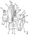
- Figure 1 is a perspective view of a vertical acting chuck together with a vertical levelling head for holding and positioning of an object or a workpiece in a wire electric discharge machine.
- the device 1 seen from left to right consists of a base part 2, in this case represented by the vertical acting chuck, an intermediate part 3 and a levelling part 4, where the intermediate part 3 and the levelling part 4 cooperate together as the levelling head. Both the workpiece and the wire electric discharge machine are not shown in this drawing.
- the workpiece can be fixed with its flat top surface to the bottom side of the levelling part 4 having a mounting surface 5.
- Figure 2 shows the intermediate part 3 and the levelling part 4 clamped together and oriented with respect to the X-Y-Z reference system of coordinates.
- Both the intermediate part 3 and the levelling part 4 have a cross-section in the shape of a letter L.
- the levelling part 4 essentially consists of a horizontal leg 6 and a vertical leg 7 and has an outer lying corner edge 8.
- the outer lying corner edge 8 is defined by the line where the outer faces of the horizontal leg 6 and the vertical leg 7 come together.
- the intermediate part 3 consists of a horizontal leg 9 and a vertical leg 10 and has an inner lying corner edge 11.
- the inner lying corner edge 11 is defined by the line where the inner faces of the horizontal leg 9 and the vertical leg 10 come together.
- the levelling part 4 can be fixed to the intermediate part 3 by means of three adjustment screws 12, 13, 14.
- a first pair of adjustment screws 12, 13 is used for adjusting the workpiece with respect to the X-Z plane of the reference system, i.e. by rotation about the Y-axis.
- the third adjustment screw 14 is used for adjusting the workpiece with respect to the Y-Z plane of the reference system, i.e. by rotation about the X-axis.
- FIG 3 the levelling part 4 and the intermediate part 3 are shown under another angle of perspective.
- the intermediate part 3 has at the vertical leg 10 a vertical rear face 15 that is equipped with a mechanical coupling system having elastic tongues 16 for establishing an accurate mechanical connection to the base part 2.
- the horizontal leg 9 of the intermediate part 3 has also screw holes 17 for mounting bolts (not shown) to mount the device 1 directly to a machine table.
- the intermediate part 3 could also be mounted to the head 30 of a tool drive e.g. the machining spindle of the Y-axis of a machining system, the so-called B-axis.
- This embodiment of the invention is shown schematically in Figure 8 .
- an L-shaped resilient or spring plate 18 is fixed to the L-shaped levelling part 4.
- a pair of first screws 19, 20, shown in Figure 4 is used to fix the horizontal leg 21 of the spring plate 18 to the horizontal bottom face 22 of the horizontal leg 6 of the levelling part 4.
- the horizontal leg 21 of the spring plate 18 also has downward bended wings 23, 24 for applying a separating force between the levelling part 4 and the intermediate part 3, acting in the direction of the Z-axis. Thereby the system can be preloaded for increased rigidity.
- the intermediate part 3 has in the middle of the horizontal leg 9 a vertical receiving aperture 25 for receiving a lug 26 extending vertically from the middle of the horizontal leg 6 of the levelling part 4.
- the receiving aperture 25 has at least one wall portion 45 arranged perpendicular to the Y-axis of the system.
- a second horizontal bore 27 through the lug 26 coincides with a first horizontal bore 28 through the horizontal leg 9 of the intermediate part 3, so that a swinging pin 29 can be inserted consecutively through the first horizontal bore 28 in the horizontal leg 9 of the intermediate part 3 and the second horizontal bore 27 in the lug 26 of the levelling part 4.
- the swinging pin 29 is of a cylindrical shape, having an outside diameter considerably smaller than the overall inner diameter of the second horizontal bore 27 through the lug 26.
- the spring plate 18 can be fixed by means of a second pair of fixing screws 31, 32 to the vertical leg 10 of the intermediate part 3. Holes 33, 34 for driving the screws 31, 32 from the outside of the levelling part 4 can be seen in Figures 2 and 4 . After the coupling of the levelling part 4 of the device 1 to the intermediate part 3 the spring plate 18 is fixed not only by the first pair of screws 19, 20, to the levelling part 4 but also by the second pair of screws 31, 32 to the intermediate part 3, thereby establishing a rigid but resilient mechanical connection of the levelling part 4 to the intermediate part 3.
- the lug 26 also has two tapered ribs 35, 36 extending in the horizontal direction from a vertical face 37 of the lug 26 and ending in a sharp edge.
- the edges of the tapered ribs 35, 36 are arranged inline and at the same distance from the vertical face 37 of the lug 26. Therefore the ribs 35, 36 of the lug 26 of the levelling part 4 can establish a line contact between the levelling part 4 and the wall portion 45 of the vertical aperture 25 in the horizontal leg 9 of the intermediate part 3.
- the contact line acts as a fulcrum for rotational movement of the levelling part 4 with respect to the intermediate part 3 rotating around an axis in parallel to the X-axis of the system i.e. perpendicular to the Y-axis of the swinging pin 29.
- the force of the spring plate 18 ensures that the ribs 35, 36 are always in contact with the wall 45 of the aperture 25.
- Adjustment of the workpiece around the Y-axis is achieved by first fixing one of the vertical adjustment screws 12, 13. The second vertical adjustment screw is then tightened, thereby increasing rigidity of the system. The adjustment around the X-axis is then done by fixing the upper horizontal third adjustment screw 14.
- the spring plate 18 is constantly acting with a spring force between the intermediate part 3 and the levelling part 4 in both directions. Adjustment of the position of the workpiece is therefore possible in both directions.
- FIG. 5 shows the rotation of the levelling part 4 with respect to the intermediate part 3 around the Y-axis of the X-Y-Z coordinate reference system.
- the coordinate system only defines the directions of the axes but not the locations of the axes.
- Figure 6 shows a cross-section of the intermediate part 3 and the levelling part 4 of the device 1 seen in the direction of the X-axis of the X-Y-Z system of coordinates.
- the rotational movement of the levelling part 4 with respect to the intermediate part 3 around the X-axis of the system can be seen.
- the relationship between the circular edge of the tapered inner ring 38 on the inner wall of the bore 27 in the lug 26 and the swinging pin 29 that is inserted in the horizontal bore 28 in the horizontal leg 9 of the intermediate part 4 can also be seen.
- Figure 7 shows the spring plate 18 having a cross-section in the shape of a letter L.
- Both the vertical leg 40 and the horizontal leg 21 of the spring plate 18 have passages 41, 42, 43, 44 for the fixing screws 19, 20, 31, 32 as well as bended wings 23, 24, 46, 47 for applying separating forces to the intermediate part 3 and the levelling part 4 acting in the direction of the Y- and Z-axes.
- Figure 8 shows an alternative use of the device 1.
- the intermediate part 3 is fixed to a head of a driving spindle for rotational driving a machining tool about the Y-axis of the machining system.
Landscapes
- Engineering & Computer Science (AREA)
- Mechanical Engineering (AREA)
- Electrical Discharge Machining, Electrochemical Machining, And Combined Machining (AREA)
Priority Applications (2)
| Application Number | Priority Date | Filing Date | Title |
|---|---|---|---|
| EP07011354A EP2002927A1 (de) | 2007-06-11 | 2007-06-11 | Vorrichtung zum Halten und Positionieren eines Gegenstandes oder Werkstücks |
| PCT/EP2008/057051 WO2008151985A1 (en) | 2007-06-11 | 2008-06-06 | Device for holding and positioning of an object or a workpiece |
Applications Claiming Priority (1)
| Application Number | Priority Date | Filing Date | Title |
|---|---|---|---|
| EP07011354A EP2002927A1 (de) | 2007-06-11 | 2007-06-11 | Vorrichtung zum Halten und Positionieren eines Gegenstandes oder Werkstücks |
Publications (1)
| Publication Number | Publication Date |
|---|---|
| EP2002927A1 true EP2002927A1 (de) | 2008-12-17 |
Family
ID=38659390
Family Applications (1)
| Application Number | Title | Priority Date | Filing Date |
|---|---|---|---|
| EP07011354A Withdrawn EP2002927A1 (de) | 2007-06-11 | 2007-06-11 | Vorrichtung zum Halten und Positionieren eines Gegenstandes oder Werkstücks |
Country Status (2)
| Country | Link |
|---|---|
| EP (1) | EP2002927A1 (de) |
| WO (1) | WO2008151985A1 (de) |
Cited By (1)
| Publication number | Priority date | Publication date | Assignee | Title |
|---|---|---|---|---|
| CN112555649A (zh) * | 2020-11-17 | 2021-03-26 | 郑州云启工业设备技术有限公司 | 一种用于通讯信号塔无线信号发射设备的安装装置 |
Families Citing this family (2)
| Publication number | Priority date | Publication date | Assignee | Title |
|---|---|---|---|---|
| WO2010127114A2 (en) | 2009-05-01 | 2010-11-04 | Oregon Health & Science University | Automated detection and counting of biomolecules using nanoparticle probes |
| CN106312657B (zh) * | 2016-11-29 | 2018-06-08 | 沈阳鼓风机集团核电泵业有限公司 | 一种定位数控镗铣加工中心的工件中心的方法及装置 |
Citations (5)
| Publication number | Priority date | Publication date | Assignee | Title |
|---|---|---|---|---|
| US5487538A (en) * | 1994-08-10 | 1996-01-30 | Giaser Tool Co. | Workpiece holding assembly |
| US5713118A (en) * | 1992-10-01 | 1998-02-03 | Chick Machine Tool, Inc. | Apparatus for positioning an element on a surface |
| US5964569A (en) * | 1997-06-30 | 1999-10-12 | Daewoo Electronics Co., Ltd. | Panel positioning device |
| US6252192B1 (en) * | 2000-01-18 | 2001-06-26 | Precision Die & Machine Company | EDM tool holder |
| CH692010A5 (de) * | 1997-09-09 | 2002-01-15 | Erowa Ag | Vorrichtung zum Aufspannen und Ausrichten eines Werkzeugs oder Werkstücks. |
-
2007
- 2007-06-11 EP EP07011354A patent/EP2002927A1/de not_active Withdrawn
-
2008
- 2008-06-06 WO PCT/EP2008/057051 patent/WO2008151985A1/en not_active Ceased
Patent Citations (5)
| Publication number | Priority date | Publication date | Assignee | Title |
|---|---|---|---|---|
| US5713118A (en) * | 1992-10-01 | 1998-02-03 | Chick Machine Tool, Inc. | Apparatus for positioning an element on a surface |
| US5487538A (en) * | 1994-08-10 | 1996-01-30 | Giaser Tool Co. | Workpiece holding assembly |
| US5964569A (en) * | 1997-06-30 | 1999-10-12 | Daewoo Electronics Co., Ltd. | Panel positioning device |
| CH692010A5 (de) * | 1997-09-09 | 2002-01-15 | Erowa Ag | Vorrichtung zum Aufspannen und Ausrichten eines Werkzeugs oder Werkstücks. |
| US6252192B1 (en) * | 2000-01-18 | 2001-06-26 | Precision Die & Machine Company | EDM tool holder |
Cited By (1)
| Publication number | Priority date | Publication date | Assignee | Title |
|---|---|---|---|---|
| CN112555649A (zh) * | 2020-11-17 | 2021-03-26 | 郑州云启工业设备技术有限公司 | 一种用于通讯信号塔无线信号发射设备的安装装置 |
Also Published As
| Publication number | Publication date |
|---|---|
| WO2008151985A1 (en) | 2008-12-18 |
Similar Documents
| Publication | Publication Date | Title |
|---|---|---|
| US20150375389A1 (en) | Device for angularly precise machining of a workpiece by a tool guided on a guide rail | |
| EP0420909A1 (de) | Geschlossenes positionierungssystem für den effektor eines roboterarms | |
| US9283658B2 (en) | Self-centering clamp | |
| JPH0899244A (ja) | 機械加工ワークピース保持組立体 | |
| US11878381B2 (en) | Tooling base assembly | |
| WO2008151985A1 (en) | Device for holding and positioning of an object or a workpiece | |
| JP5148333B2 (ja) | ツールホルダ位置決め装置 | |
| CN105792985B (zh) | 工具夹持装置 | |
| CN106312611A (zh) | 发动机缸体钻斜孔加工夹具 | |
| CN115921951B (zh) | 一种加工斜喷油孔的加工装置以及加工方法 | |
| JPS622939B2 (de) | ||
| JP2566922B2 (ja) | 基準部材を備えた装置 | |
| JP4594608B2 (ja) | 工作機械を位置合わせするための方法及び装置 | |
| CN206169673U (zh) | 发动机缸体钻斜孔加工夹具 | |
| JP3763194B2 (ja) | 溶接部品の機械加工装置 | |
| JP5898822B1 (ja) | ワーク保持装置、及びワーク保持装置付きアリ溝摺動ステージ | |
| CN202922260U (zh) | 臂架类零件浮动支撑夹具 | |
| CN219837671U (zh) | 柔性自动线用以平面为基准的阀套零件角向预定位夹具 | |
| CN108941794B (zh) | 齿轮安装机构及具有其的机床 | |
| CN220007051U (zh) | 工件分度工装 | |
| CN217860022U (zh) | 夹持装置 | |
| CN107931929B (zh) | 一种自适应调节工装夹具 | |
| CN222763252U (zh) | 一种转接板支架及加工设备 | |
| CN211438474U (zh) | 一种可倾斜的治具机构 | |
| CN216097596U (zh) | 一种可多重固定的工装夹具 |
Legal Events
| Date | Code | Title | Description |
|---|---|---|---|
| PUAI | Public reference made under article 153(3) epc to a published international application that has entered the european phase |
Free format text: ORIGINAL CODE: 0009012 |
|
| AK | Designated contracting states |
Kind code of ref document: A1 Designated state(s): AT BE BG CH CY CZ DE DK EE ES FI FR GB GR HU IE IS IT LI LT LU LV MC MT NL PL PT RO SE SI SK TR |
|
| AX | Request for extension of the european patent |
Extension state: AL BA HR MK RS |
|
| AKX | Designation fees paid | ||
| REG | Reference to a national code |
Ref country code: DE Ref legal event code: 8566 |
|
| STAA | Information on the status of an ep patent application or granted ep patent |
Free format text: STATUS: THE APPLICATION IS DEEMED TO BE WITHDRAWN |
|
| 18D | Application deemed to be withdrawn |
Effective date: 20090618 |