EP2002996A1 - Roue de secours anti-explosion à l'intérieur d'un pneumatique - Google Patents
Roue de secours anti-explosion à l'intérieur d'un pneumatique Download PDFInfo
- Publication number
- EP2002996A1 EP2002996A1 EP07720414A EP07720414A EP2002996A1 EP 2002996 A1 EP2002996 A1 EP 2002996A1 EP 07720414 A EP07720414 A EP 07720414A EP 07720414 A EP07720414 A EP 07720414A EP 2002996 A1 EP2002996 A1 EP 2002996A1
- Authority
- EP
- European Patent Office
- Prior art keywords
- tire
- outer circle
- resilient
- resilient outer
- circle
- Prior art date
- Legal status (The legal status is an assumption and is not a legal conclusion. Google has not performed a legal analysis and makes no representation as to the accuracy of the status listed.)
- Granted
Links
Images



Classifications
-
- B—PERFORMING OPERATIONS; TRANSPORTING
- B60—VEHICLES IN GENERAL
- B60C—VEHICLE TYRES; TYRE INFLATION; TYRE CHANGING; CONNECTING VALVES TO INFLATABLE ELASTIC BODIES IN GENERAL; DEVICES OR ARRANGEMENTS RELATED TO TYRES
- B60C17/00—Tyres characterised by means enabling restricted operation in damaged or deflated condition; Accessories therefor
- B60C17/01—Tyres characterised by means enabling restricted operation in damaged or deflated condition; Accessories therefor utilising additional inflatable supports which become load-supporting in emergency
- B60C17/02—Tyres characterised by means enabling restricted operation in damaged or deflated condition; Accessories therefor utilising additional inflatable supports which become load-supporting in emergency inflated or expanded in emergency only
-
- B—PERFORMING OPERATIONS; TRANSPORTING
- B60—VEHICLES IN GENERAL
- B60C—VEHICLE TYRES; TYRE INFLATION; TYRE CHANGING; CONNECTING VALVES TO INFLATABLE ELASTIC BODIES IN GENERAL; DEVICES OR ARRANGEMENTS RELATED TO TYRES
- B60C17/00—Tyres characterised by means enabling restricted operation in damaged or deflated condition; Accessories therefor
- B60C17/01—Tyres characterised by means enabling restricted operation in damaged or deflated condition; Accessories therefor utilising additional inflatable supports which become load-supporting in emergency
-
- Y—GENERAL TAGGING OF NEW TECHNOLOGICAL DEVELOPMENTS; GENERAL TAGGING OF CROSS-SECTIONAL TECHNOLOGIES SPANNING OVER SEVERAL SECTIONS OF THE IPC; TECHNICAL SUBJECTS COVERED BY FORMER USPC CROSS-REFERENCE ART COLLECTIONS [XRACs] AND DIGESTS
- Y10—TECHNICAL SUBJECTS COVERED BY FORMER USPC
- Y10T—TECHNICAL SUBJECTS COVERED BY FORMER US CLASSIFICATION
- Y10T152/00—Resilient tires and wheels
- Y10T152/10—Tires, resilient
- Y10T152/10495—Pneumatic tire or inner tube
- Y10T152/10522—Multiple chamber
-
- Y—GENERAL TAGGING OF NEW TECHNOLOGICAL DEVELOPMENTS; GENERAL TAGGING OF CROSS-SECTIONAL TECHNOLOGIES SPANNING OVER SEVERAL SECTIONS OF THE IPC; TECHNICAL SUBJECTS COVERED BY FORMER USPC CROSS-REFERENCE ART COLLECTIONS [XRACs] AND DIGESTS
- Y10—TECHNICAL SUBJECTS COVERED BY FORMER USPC
- Y10T—TECHNICAL SUBJECTS COVERED BY FORMER US CLASSIFICATION
- Y10T428/00—Stock material or miscellaneous articles
- Y10T428/13—Hollow or container type article [e.g., tube, vase, etc.]
Definitions
- the invention relates to a vehicle tire safety device, and more particularly, to an airbag device for a vehicle tire, which allows the tire to continue operating safely after failure, e.g., explosion or puncture, without loss of stability and for an extended period of time without the need for tire replacement.
- failure e.g., explosion or puncture
- the solutions are mainly classified into two types.
- the first type is to install a supporting rim inside of the tire. See, e.g., Chinese Pat. Publ. No. CN1616264A . While the tire structure is not changed, the outer diameter of the supporting rim is less than the inner diameter of the tire tread and is more than the outer diameter of the hub. If the air pressure of the tire is lost, the weight of the auto will be supported by the supporting rim so that the falling height of the wheel is decreased to realize a certain degree of safety protection. However, since the outer diameter of the supporting rim is less than the inner diameter of the tire tread, the tire rolling resistance is increased.
- the other type is to improve the tire structure to allow the tire to have certain supporting strength after puncture to allow the tire to run a further distance.
- the existing fail safe tires are described, e.g. in China Pat. CN1264343A , China Pat. CN1265067A , and China Pat. CN1689847A .
- the fail safe tire has a similar shape and shares the same installation method as a normal pneumatic tire. However, since enough supporting strength needs to be ensured, the riding comfort is decreased and the resistance of the wheel is increased during normal operation.
- an airbag device for a vehicle tire capable of stabilizing the auto timely when the tire is exploding or being punctured suddenly, keeping a normal running performance, and meanwhile, ensuring the driving comfort.
- an airbag device for a vehicle tire comprising: a resilient outer circle installed between the tire and the hub, and an inner circle serving to support the resilient outer circle.
- the normal tire air pressure of the tire is utilized to compress the resilient outer circle to the hub to form enough space between the resilient outer circle and the inner surface of the tire and thereby to keep the resilient outer circle from contacting the inner surface of the tire tread.
- the resilient outer circle will expand instantly based on its self resilience to contact the inner surface of the tire tread and, under the supporting of the inner circle, to support the weight of the vehicle. Therefore, the vehicle can run stably an additional distance without changing the damaged tire.
- the device further comprises an airbag for compressing the resilient outer circle to the hub under normal tire air pressure, the airbag being disposed around the outer surface of the resilient outer circle.
- the device further comprises an airbag for compressing the resilient outer circle to the hub under normal tire air pressure, the airbag being disposed at the inner surface of the resilient outer circle.
- the cross section of the airbag is in a shape of an ⁇ , a C or an O.
- the cross section of the resilient outer circle is in a shape of an ⁇ , a C or an O.
- the inner circle has a single-side supporting structure or a double-side supporting symmetrical structure; a bottom end of the resilient supporting structure being affixed to the hub via a tightening ring or to the inner edge of the tire; the resilient outer circle is slidable on the resilient supporting structure; a non-return structure is disposed on the resilient supporting structure, so that the resilient outer circle is slidable to the top of the resilient supporting structure when normal tire air pressure is lost and is not slidable back under the function of the tire tread unless the tire is refilled with air and the sides of the resilient outer circle are pressed together; and a lock slot is disposed at the bottom end of the resilient supporting structure to lock the resilient outer circle when it is compressed so as to avoid the resilient outer circle swinging out by the centrifugal force.
- the inner circle comprises an inner supporting member and a lateral supporting member, the bottom end of the lateral supporting member is connected with a push rod, and a connection point between the lateral supporting member and the push rod serves to lock the bottom end of the inner supporting member whereby fixing the inner supporting member; an airbag is installed between the inner supporting member and the resilient outer circle; during normal operation of the tire, the resilient outer circle is compressed and locked at the lowest point of the inner supporting member; after loss of normal tire pressure, the resilient outer circle is released from the lowest point of the inner supporting member and moves to the stop point and then is locked so that it cannot return back; the top end of the inner supporting member is further connected with a tightening ring.
- the inner circle and the resilient outer circle are formed as one piece; during normal operation of the tire, the air pressure of the tire first compresses the side of the an airbag device for a vehicle tire inwardly deformed, and then the resilient outer circle is inwardly compressed until it is locked by a clip; after loss of normal tire pressure, the clip is released, the inner circle and the resilient outer circle bounce quickly upwards simultaneously under the function of resilient force.
- a compressible space is formed in the airbag between the outer circle and the hub close to the hub side to avoid air pressure in the tire over a certain threshold.
- An airbag device for a vehicle tire without the need to fill in air in accordance with the invention having the functions of limiting the air pressure of the tire, proofing tire explosion, and acting as a spare wheel is installed inside of the tire, while the structure of the existing normal tire is kept unchanged.
- the airbag device When the air pressure of the tire is normal, the airbag device is in a compressed status and does not contact the tread and inner surface of the tire, and a certain space therebetween is kept, so that the driving comfort and rolling resistance are not negatively influenced.
- a certain degree of pressure limiting can be realized when the inner pressure increases to a certain level.
- the airbag device can bounce instantly to support the tire tread to keep the tire running in a normal tire air pressure status, so that the vehicle can still be running a further distance at a relatively high speed without the risk of tire explosion and accidents.
- the safety performance of the tire is improved, and the tire can be designed to be lighter, so that the tire resistance can be relatively decreased and the driving comfortability is relatively increased.
- the tire an airbag device for a vehicle tire of the invention is suitable for various tires and thus has a wide applicability.
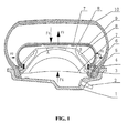
- FIG. 1 is a structural view of an airbag device for a vehicle tire in accordance with one embodiment of the invention
- FIG. 2 is a structural view of the an airbag device for a vehicle tire of FIG. 1 expanding after tire explosion;
- FIG. 3 is a structure view of an airbag device for a vehicle tire in accordance with another embodiment of the invention.
- FIG. 4 is a structural view of the airbag device for a vehicle tire of FIG. 3 expanding after tire explosion;
- FIG. 5 is a structure view of an airbag device for a vehicle tire in accordance with another embodiment of the invention.
- FIG. 6 is a structural view of the airbag device for a vehicle tire of FIG. 5 expanding after tire explosion;
- FIG. 7 is a structural view an airbag device for a vehicle tire in accordance with another embodiment of the invention.
- FIG. 8 is a structural view of an airbag device for a vehicle tire in accordance with another embodiment of the invention.
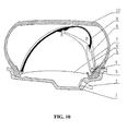
- FIG. 9 is a structural view of an airbag device for a vehicle tire in accordance with another embodiment of the invention.
- FIG. 10 is a structural view of the airbag device for a vehicle tire of FIG. 9 expanding after tire explosion;
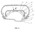
- FIG. 11 is a structural view of an airbag device for a vehicle tire in accordance with another embodiment of the invention.
- FIG. 12 is a structural view of the airbag device for a vehicle tire of FIG. 11 expanding after tire explosion.
- an airbag device for a vehicle tire comprises a resilient outer circle, an inner circle, and an airbag.
- the resilient outer circle is formed through the connection of an outer circle9 and is compressible.
- the inner circle comprises an inner circle 8 and is fixed on the hub 1 by a tightening ring 3.
- the tightening ring 3 is made of steel wire or carbon fiber.
- the outer circle of the airbag device is a compressible resilient body connected by a plurality of outer supporting members 9. In the event that a tire explodes, as shown in FIG. 2 , the bottom end of the outer circle9 slides on the section labeled BC of the inner circle 8.
- the tangential direction of the circumference of the outer circle has a certain degree of resilience.
- the two resilient sides of the outer circle9 have enough resilient force F2 to ensure that the inner circle 8 bounces instantly and is then locked at point B.
- the inner and outer supporting members are made of light resilient alloy material to ensure that the weight of the airbag device (and the tire comprising it) is as light as possible.
- the BC section of the inner circle 8 should have enough strength, and the AB and DB sections should have good resilience and anti-fatigue performance.
- An airbag 7 is added to cover the outer surface of the supporting members, and is connected with the atmosphere through a vent hole 4. One or more vent holes can be set on the circumference of the airbag.
- the airbag When filling in air for the tire, the airbag is compressed from all sides, and under the function of the side pressure F1 and the upper pressure F3, the outer circle9 is released from point B and slides to point C and then is locked at point C (as shown in FIG. 1 ). Therefore, enough space is kept between the supporting member inside of the tire and the inner surface of the tire tread so that the operation of the tire under normal tire air pressure is not influenced.
- the airbag is normally made of hermetic compound material and has a certain degree of anti-pulling performance, and should be as light as possible.
- the upper side of the airbag can be located underneath the outer circle9 and is capable of compressing the outer circleby means of pulling.
- the connection piece 5 serves to lock the tightening ring 3 onto the tire.
- the airbag Under normal tire air pressure, the airbag is in a compressed status, the inner side of the airbag can be set capable of being compressed further according to demand, the motion pressure of the inner side of the airbag is higher than the normal tire pressure and is lower than the safe pressure of the tire.
- the tire pressure is increasing to the safe pressure due to the increase of tire temperature as the auto is running at high speed
- the inner side of the airbag can be further compressed to the dash line to limit the tire pressure increase.
- the temperature and air pressure of the tire decrease to the normal value, the inner side of the airbag will automatically return to normal.
- the weight of the airbag device is required to be as small as possible.
- the device can be made of light alloy or carbon fiber material and can have a hollow thin wall structure to control the weight of the tire. A certain degree of anti-fatigue performance is required for the frequently resilient bent portion of the airbag device.
- the inner circle and the resilient outer circle are designed as two separate parts.
- the size of the resilient outer circle can be changed accordingly since the resilient outer circle is sliding on the inner circle.
- the inner circle and resilient outer circle are formed as one piece.
- the resilient deformation of the inner circle 8 is utilized to adjust the size of the resilient outer circle 9.
- FIG. 4 when the tire air pressure is normal, the air pressure compresses the inner circle bent deformed inwardly, and at the same time, the resilient outer circle 9 is compressed inwardly until it is locked by clip 16.
- FIG. 4 when the air pressure of the tire is lost, the clip 16 is released and deformed under the function of tire tread pressure, and the airbag device is then unfolding.
- At least one inner supporting member 11 and at least one lateral supporting member 12 serve to form a fixed supporting member.
- the bottom end of the lateral supporting member 12 is connected with a push rod 15, and the connection point (point K) therebetween serves to lock the bottom end of, and thus to fix, the inner supporting member 11.
- point K connection point
- the inner supporting member is then capable of being bent inwardly to push the tire edge to the deep slot of the hub so that the tire can be disassembled and repaired.
- the airbag 7 can be located between the inner supporting member 11 and the outer circle9. Under normal tire pressure, the tire pressure is utilized to compress the outer circle9 to point B and then is fixedly-locked there. As shown in FIG. 6 , once the air pressure of the tire is lost, the outer circle9 is released from point B and, under the function of resilient force, is sliding to point A and is locked there.
- the tightening ring 13 is connected with the fixed supporting member, and is clip-locked on the hub.
- an airbag device having a variable outer diameter is installed inside of the tire, and is set with an airbag connected with the outer atmosphere.
- the pressure of the tire is utilized to compress the airbag so as to decrease the outer diameter of the airbag device and also to lock the airbag device.
- a certain space is formed between the airbag device and the inner surface of the tire so that the operation of the tire is not influenced.
- the compressible portion of the airbag can be further compressed to limit the increase of the tire air pressure.
- the airbag device will bounce instantly under the function of self resilience and centrifugal force to support the flat tire so that the auto can be run a further distance at relatively high speed.
- the airbag device is also applicable for a tire having an inner tire, and can be compressed by the inner tire.
- a foam elastic material can be coated on the upper surface of the outer supporting member.
- the two-side symmetrical supporting structure in Example 1 can be changed to a single side supporting structure to simplify the structure so as to properly decrease the device weight and cost.
- the cross section of the airbag can be designed in a shape of an ⁇ or an O.
- the two side edges of the ⁇ -shaped airbag are clipped on the tire ring 51, and the tire ring 51 also serves to compress tightly the two side edges of the ⁇ -shaped airbag onto the hub.
- An air chamber 71 is formed between the ⁇ -shaped airbag and the tire.
- the vent hole 4 is passing through the ⁇ -shaped airbag to fill in the tire, the outer circle 9 will be compressed simultaneously.
- the space formed between the ⁇ -shaped airbag and the hub is connected to the outer air through the gap formed by the vent hole, equivalent to a compressible airbag.
- the bottom 31 of the inner supporting member is also hooked on the tire ring 51.
Landscapes
- Engineering & Computer Science (AREA)
- Mechanical Engineering (AREA)
- Tires In General (AREA)
- Heating, Cooling, Or Curing Plastics Or The Like In General (AREA)
- Air Bags (AREA)
- Compositions Of Macromolecular Compounds (AREA)
Applications Claiming Priority (2)
| Application Number | Priority Date | Filing Date | Title |
|---|---|---|---|
| CN200610038933 | 2006-03-20 | ||
| PCT/CN2007/000834 WO2007107087A1 (fr) | 2006-03-20 | 2007-03-15 | Roue de secours anti-explosion à l'intérieur d'un pneumatique |
Publications (3)
| Publication Number | Publication Date |
|---|---|
| EP2002996A1 true EP2002996A1 (fr) | 2008-12-17 |
| EP2002996A4 EP2002996A4 (fr) | 2009-03-11 |
| EP2002996B1 EP2002996B1 (fr) | 2010-10-06 |
Family
ID=38522030
Family Applications (1)
| Application Number | Title | Priority Date | Filing Date |
|---|---|---|---|
| EP07720414A Not-in-force EP2002996B1 (fr) | 2006-03-20 | 2007-03-15 | Roue de secours anti-explosion à l'intérieur d'un pneumatique |
Country Status (7)
| Country | Link |
|---|---|
| US (1) | US8261792B2 (fr) |
| EP (1) | EP2002996B1 (fr) |
| JP (1) | JP5107995B2 (fr) |
| KR (1) | KR101330872B1 (fr) |
| AT (1) | ATE483594T1 (fr) |
| DE (1) | DE602007009655D1 (fr) |
| WO (1) | WO2007107087A1 (fr) |
Cited By (2)
| Publication number | Priority date | Publication date | Assignee | Title |
|---|---|---|---|---|
| CN107933205A (zh) * | 2017-10-18 | 2018-04-20 | 南京航空航天大学 | 一种气压自适应负泊松比结构防爆轮胎及其设计方法 |
| CN110696552A (zh) * | 2019-11-11 | 2020-01-17 | 张欢 | 一种具有安全气囊的汽车轮毂 |
Families Citing this family (9)
| Publication number | Priority date | Publication date | Assignee | Title |
|---|---|---|---|---|
| KR101034741B1 (ko) | 2010-12-01 | 2011-05-17 | 함성민 | 펑크 대비용 런플랫 타이어 |
| TW201434679A (zh) * | 2013-03-13 | 2014-09-16 | Shui-Zhen Xu | 一種車胎防刃刺防爆改良結構 |
| TWI615291B (zh) * | 2016-07-26 | 2018-02-21 | Hung Hsiang Huang | 防穿刺降爆輪胎之防穿刺降爆膠製造設備及其單雙並聯槍體組件 |
| CN106218325A (zh) * | 2016-07-29 | 2016-12-14 | 无锡康柏斯机械科技有限公司 | 一种车轮脱离时车体防倾覆装置 |
| CN108639468A (zh) * | 2018-05-31 | 2018-10-12 | 青岛东平骏川工业自动化设备有限公司 | 一种包装整形气囊 |
| CN112606884A (zh) * | 2020-12-28 | 2021-04-06 | 赵新飞 | 一种物流用方便推行的运输车 |
| CN114379291B (zh) * | 2022-03-24 | 2022-06-07 | 山东玲珑轮胎股份有限公司 | 一种轮胎内支撑安全锁紧装置 |
| CN115071341A (zh) * | 2022-08-22 | 2022-09-20 | 江苏彼尔汽车部件有限公司 | 一种汽车轮毂锻件结构 |
| CN116729026B (zh) * | 2023-07-21 | 2026-01-23 | 广汽丰田汽车有限公司 | 备用防护胎及其轮胎防护方法 |
Family Cites Families (23)
| Publication number | Priority date | Publication date | Assignee | Title |
|---|---|---|---|---|
| US3724521A (en) * | 1971-05-06 | 1973-04-03 | Exxon Research Engineering Co | Anti-flat device |
| US3828836A (en) * | 1972-12-13 | 1974-08-13 | C Bradley | Safety wheel and tire securing assembly |
| DE2309814A1 (de) * | 1973-02-28 | 1974-09-12 | Fritz K Strauss | Radfelge mit automatisch kombiniert arbeitender notlaufeinrichtung |
| US4137894A (en) * | 1977-06-17 | 1979-02-06 | The Firestone Tire & Rubber Company | Pneumatic tire, rim and run-flat system combination |
| FR2430323A1 (fr) * | 1978-07-03 | 1980-02-01 | Uniroyal | Chambre a air composite de securite pour roue de vehicule et ses elements composants |
| US6026878A (en) | 1997-05-29 | 2000-02-22 | The Goodyear Tire & Rubber Company | Inextensible high temperature resistant tire |
| US5871600A (en) | 1997-05-29 | 1999-02-16 | The Goodyear Tire & Rubber Company | Runflat tire with different modulus or elongation carcass cords |
| FR2804067B1 (fr) * | 2000-01-20 | 2002-02-22 | Michelin Soc Tech | Membrane de soutien de bande de roulement |
| JP2002067632A (ja) * | 2000-08-24 | 2002-03-08 | Bridgestone Corp | 安全空気入りタイヤ |
| DE60133763T2 (de) * | 2000-11-30 | 2009-06-25 | Bridgestone Corp. | Luftschlauch für sicherheitsreifen |
| JP4633946B2 (ja) * | 2001-02-13 | 2011-02-16 | 不二精工株式会社 | ランフラットタイヤとリムとの組立体 |
| JP3424041B2 (ja) * | 2001-06-20 | 2003-07-07 | 邱▲いく▼樸 | タイヤの制御不能防止装置 |
| JP4508535B2 (ja) * | 2002-06-18 | 2010-07-21 | 株式会社ブリヂストン | 安全タイヤおよび安全タイヤ用中子 |
| JP2004330985A (ja) * | 2003-05-12 | 2004-11-25 | Topy Ind Ltd | エアバッグ式ランフラットホイール |
| JP2005053383A (ja) * | 2003-08-06 | 2005-03-03 | Bridgestone Corp | 安全タイヤ及び安全タイヤ用空気のう |
| CN1616264A (zh) | 2003-11-13 | 2005-05-18 | 南港轮胎股份有限公司 | 安全轮胎及其支撑装置 |
| JP4367916B2 (ja) * | 2003-12-04 | 2009-11-18 | 横浜ゴム株式会社 | 空気入りタイヤ |
| CN2688521Y (zh) * | 2004-02-11 | 2005-03-30 | 阚明玉 | 汽车爆胎保安轮 |
| FR2867107B1 (fr) * | 2004-03-04 | 2006-04-28 | Michelin Soc Tech | Corps servant de support a un pneumatique en cas de degonflage et ensemble pneumatique equipe avec un tel corps. |
| DE602004003243T2 (de) | 2004-04-22 | 2007-07-05 | The Goodyear Tire & Rubber Co., Akron | Pannenlauffähiger luftreifen |
| JP2006069315A (ja) * | 2004-09-01 | 2006-03-16 | Bridgestone Corp | 安全タイヤ用空気のう、これを用いた安全タイヤ及びかかる空気のうの製造方法 |
| KR100711622B1 (ko) | 2005-09-13 | 2007-04-30 | 금호타이어 주식회사 | 완충역할을 하는 런 플랫 타이어의 스틸 지지체 |
| FR2893536A1 (fr) * | 2005-11-22 | 2007-05-25 | Michelin Soc Tech | Systeme de roulage a plat comprenant des cellules autogonflantes |
-
2007
- 2007-03-15 DE DE602007009655T patent/DE602007009655D1/de active Active
- 2007-03-15 AT AT07720414T patent/ATE483594T1/de not_active IP Right Cessation
- 2007-03-15 WO PCT/CN2007/000834 patent/WO2007107087A1/fr not_active Ceased
- 2007-03-15 EP EP07720414A patent/EP2002996B1/fr not_active Not-in-force
- 2007-03-15 JP JP2009500690A patent/JP5107995B2/ja not_active Expired - Fee Related
- 2007-03-15 KR KR1020087025496A patent/KR101330872B1/ko not_active Expired - Fee Related
-
2008
- 2008-09-12 US US12/209,414 patent/US8261792B2/en not_active Expired - Fee Related
Cited By (4)
| Publication number | Priority date | Publication date | Assignee | Title |
|---|---|---|---|---|
| CN107933205A (zh) * | 2017-10-18 | 2018-04-20 | 南京航空航天大学 | 一种气压自适应负泊松比结构防爆轮胎及其设计方法 |
| CN107933205B (zh) * | 2017-10-18 | 2019-12-24 | 南京航空航天大学 | 一种气压自适应负泊松比结构防爆轮胎及其设计方法 |
| CN110696552A (zh) * | 2019-11-11 | 2020-01-17 | 张欢 | 一种具有安全气囊的汽车轮毂 |
| CN110696552B (zh) * | 2019-11-11 | 2021-06-04 | 江苏东之宝车业股份有限公司 | 一种具有安全气囊的汽车轮毂 |
Also Published As
| Publication number | Publication date |
|---|---|
| JP2009530162A (ja) | 2009-08-27 |
| KR20080109035A (ko) | 2008-12-16 |
| ATE483594T1 (de) | 2010-10-15 |
| US8261792B2 (en) | 2012-09-11 |
| KR101330872B1 (ko) | 2013-11-18 |
| WO2007107087A1 (fr) | 2007-09-27 |
| EP2002996A4 (fr) | 2009-03-11 |
| US20090000719A1 (en) | 2009-01-01 |
| EP2002996B1 (fr) | 2010-10-06 |
| DE602007009655D1 (de) | 2010-11-18 |
| JP5107995B2 (ja) | 2012-12-26 |
Similar Documents
| Publication | Publication Date | Title |
|---|---|---|
| EP2002996B1 (fr) | Roue de secours anti-explosion à l'intérieur d'un pneumatique | |
| KR100210480B1 (ko) | 자립 카커스를 가진 자동차 타이어 | |
| EP1574360B1 (fr) | Silencieux | |
| RU2230672C2 (ru) | Колесо с шиной для транспортных средств | |
| JP2008308125A (ja) | 安全タイヤ | |
| US20150013870A1 (en) | Pneumatic tire security system employing internal high pressure air bag | |
| US8978723B2 (en) | Solid vacuum wheel and tire assembly | |
| CN100462245C (zh) | 胎内自动防爆备用轮 | |
| CN100513209C (zh) | 泄气时作为轮胎支撑的内体和装有这种内体的轮胎组件 | |
| CN115848071A (zh) | 轮胎插入件和包括所述插入件的车辆车轮 | |
| US10696095B2 (en) | Foam tire flap for low pressure applications | |
| US7096907B2 (en) | Run-flat support ring with integrated shelf design and improved mounting features | |
| CN1328073C (zh) | 轮胎/车轮组装体 | |
| CN108725102A (zh) | 汽车防爆轮胎 | |
| US5505241A (en) | Tire preservation device | |
| US20050269007A1 (en) | Run-flat support ring with internal fin | |
| JP5005697B2 (ja) | 車両ホイール用インターフェースディスク | |
| CN217455542U (zh) | 防爆轮胎 | |
| CN216443420U (zh) | 一种适用于沙漠宽基胎的爆胎应急装置 | |
| WO1994026541A1 (fr) | Bandage pneumatique de securite | |
| JP2008189131A (ja) | ランフラットタイヤ及びランフラットタイヤとリムとの組立体 | |
| JP2019112038A (ja) | 空気入りタイヤ | |
| EP2022650A1 (fr) | Pneu | |
| JP2007008466A (ja) | フラット走行を可能にするインサートを有する組立体の改良 | |
| JP4367916B2 (ja) | 空気入りタイヤ |
Legal Events
| Date | Code | Title | Description |
|---|---|---|---|
| PUAI | Public reference made under article 153(3) epc to a published international application that has entered the european phase |
Free format text: ORIGINAL CODE: 0009012 |
|
| 17P | Request for examination filed |
Effective date: 20081019 |
|
| AK | Designated contracting states |
Kind code of ref document: A1 Designated state(s): AT BE BG CH CY CZ DE DK EE ES FI FR GB GR HU IE IS IT LI LT LU LV MC MT NL PL PT RO SE SI SK TR |
|
| A4 | Supplementary search report drawn up and despatched |
Effective date: 20090210 |
|
| RIC1 | Information provided on ipc code assigned before grant |
Ipc: B60C 17/02 20060101AFI20090204BHEP Ipc: B60C 17/06 20060101ALI20090204BHEP |
|
| 17Q | First examination report despatched |
Effective date: 20090305 |
|
| GRAP | Despatch of communication of intention to grant a patent |
Free format text: ORIGINAL CODE: EPIDOSNIGR1 |
|
| GRAS | Grant fee paid |
Free format text: ORIGINAL CODE: EPIDOSNIGR3 |
|
| GRAA | (expected) grant |
Free format text: ORIGINAL CODE: 0009210 |
|
| AK | Designated contracting states |
Kind code of ref document: B1 Designated state(s): AT BE BG CH CY CZ DE DK EE ES FI FR GB GR HU IE IS IT LI LT LU LV MC MT NL PL PT RO SE SI SK TR |
|
| REG | Reference to a national code |
Ref country code: GB Ref legal event code: FG4D |
|
| REG | Reference to a national code |
Ref country code: CH Ref legal event code: EP |
|
| REG | Reference to a national code |
Ref country code: IE Ref legal event code: FG4D |
|
| REF | Corresponds to: |
Ref document number: 602007009655 Country of ref document: DE Date of ref document: 20101118 Kind code of ref document: P |
|
| REG | Reference to a national code |
Ref country code: NL Ref legal event code: VDEP Effective date: 20101006 |
|
| PG25 | Lapsed in a contracting state [announced via postgrant information from national office to epo] |
Ref country code: SI Free format text: LAPSE BECAUSE OF FAILURE TO SUBMIT A TRANSLATION OF THE DESCRIPTION OR TO PAY THE FEE WITHIN THE PRESCRIBED TIME-LIMIT Effective date: 20101006 |
|
| LTIE | Lt: invalidation of european patent or patent extension |
Effective date: 20101006 |
|
| PG25 | Lapsed in a contracting state [announced via postgrant information from national office to epo] |
Ref country code: LT Free format text: LAPSE BECAUSE OF FAILURE TO SUBMIT A TRANSLATION OF THE DESCRIPTION OR TO PAY THE FEE WITHIN THE PRESCRIBED TIME-LIMIT Effective date: 20101006 |
|
| PG25 | Lapsed in a contracting state [announced via postgrant information from national office to epo] |
Ref country code: AT Free format text: LAPSE BECAUSE OF FAILURE TO SUBMIT A TRANSLATION OF THE DESCRIPTION OR TO PAY THE FEE WITHIN THE PRESCRIBED TIME-LIMIT Effective date: 20101006 Ref country code: LV Free format text: LAPSE BECAUSE OF FAILURE TO SUBMIT A TRANSLATION OF THE DESCRIPTION OR TO PAY THE FEE WITHIN THE PRESCRIBED TIME-LIMIT Effective date: 20101006 Ref country code: NL Free format text: LAPSE BECAUSE OF FAILURE TO SUBMIT A TRANSLATION OF THE DESCRIPTION OR TO PAY THE FEE WITHIN THE PRESCRIBED TIME-LIMIT Effective date: 20101006 Ref country code: IS Free format text: LAPSE BECAUSE OF FAILURE TO SUBMIT A TRANSLATION OF THE DESCRIPTION OR TO PAY THE FEE WITHIN THE PRESCRIBED TIME-LIMIT Effective date: 20110206 Ref country code: PT Free format text: LAPSE BECAUSE OF FAILURE TO SUBMIT A TRANSLATION OF THE DESCRIPTION OR TO PAY THE FEE WITHIN THE PRESCRIBED TIME-LIMIT Effective date: 20110207 Ref country code: FI Free format text: LAPSE BECAUSE OF FAILURE TO SUBMIT A TRANSLATION OF THE DESCRIPTION OR TO PAY THE FEE WITHIN THE PRESCRIBED TIME-LIMIT Effective date: 20101006 Ref country code: SE Free format text: LAPSE BECAUSE OF FAILURE TO SUBMIT A TRANSLATION OF THE DESCRIPTION OR TO PAY THE FEE WITHIN THE PRESCRIBED TIME-LIMIT Effective date: 20101006 Ref country code: BG Free format text: LAPSE BECAUSE OF FAILURE TO SUBMIT A TRANSLATION OF THE DESCRIPTION OR TO PAY THE FEE WITHIN THE PRESCRIBED TIME-LIMIT Effective date: 20110106 |
|
| PG25 | Lapsed in a contracting state [announced via postgrant information from national office to epo] |
Ref country code: GR Free format text: LAPSE BECAUSE OF FAILURE TO SUBMIT A TRANSLATION OF THE DESCRIPTION OR TO PAY THE FEE WITHIN THE PRESCRIBED TIME-LIMIT Effective date: 20110107 Ref country code: BE Free format text: LAPSE BECAUSE OF FAILURE TO SUBMIT A TRANSLATION OF THE DESCRIPTION OR TO PAY THE FEE WITHIN THE PRESCRIBED TIME-LIMIT Effective date: 20101006 |
|
| PG25 | Lapsed in a contracting state [announced via postgrant information from national office to epo] |
Ref country code: ES Free format text: LAPSE BECAUSE OF FAILURE TO SUBMIT A TRANSLATION OF THE DESCRIPTION OR TO PAY THE FEE WITHIN THE PRESCRIBED TIME-LIMIT Effective date: 20110117 Ref country code: CZ Free format text: LAPSE BECAUSE OF FAILURE TO SUBMIT A TRANSLATION OF THE DESCRIPTION OR TO PAY THE FEE WITHIN THE PRESCRIBED TIME-LIMIT Effective date: 20101006 Ref country code: EE Free format text: LAPSE BECAUSE OF FAILURE TO SUBMIT A TRANSLATION OF THE DESCRIPTION OR TO PAY THE FEE WITHIN THE PRESCRIBED TIME-LIMIT Effective date: 20101006 |
|
| PLBE | No opposition filed within time limit |
Free format text: ORIGINAL CODE: 0009261 |
|
| STAA | Information on the status of an ep patent application or granted ep patent |
Free format text: STATUS: NO OPPOSITION FILED WITHIN TIME LIMIT |
|
| PG25 | Lapsed in a contracting state [announced via postgrant information from national office to epo] |
Ref country code: SK Free format text: LAPSE BECAUSE OF FAILURE TO SUBMIT A TRANSLATION OF THE DESCRIPTION OR TO PAY THE FEE WITHIN THE PRESCRIBED TIME-LIMIT Effective date: 20101006 Ref country code: DK Free format text: LAPSE BECAUSE OF FAILURE TO SUBMIT A TRANSLATION OF THE DESCRIPTION OR TO PAY THE FEE WITHIN THE PRESCRIBED TIME-LIMIT Effective date: 20101006 Ref country code: PL Free format text: LAPSE BECAUSE OF FAILURE TO SUBMIT A TRANSLATION OF THE DESCRIPTION OR TO PAY THE FEE WITHIN THE PRESCRIBED TIME-LIMIT Effective date: 20101006 Ref country code: RO Free format text: LAPSE BECAUSE OF FAILURE TO SUBMIT A TRANSLATION OF THE DESCRIPTION OR TO PAY THE FEE WITHIN THE PRESCRIBED TIME-LIMIT Effective date: 20101006 |
|
| 26N | No opposition filed |
Effective date: 20110707 |
|
| PG25 | Lapsed in a contracting state [announced via postgrant information from national office to epo] |
Ref country code: MC Free format text: LAPSE BECAUSE OF NON-PAYMENT OF DUE FEES Effective date: 20110331 |
|
| REG | Reference to a national code |
Ref country code: CH Ref legal event code: PL |
|
| REG | Reference to a national code |
Ref country code: DE Ref legal event code: R097 Ref document number: 602007009655 Country of ref document: DE Effective date: 20110707 |
|
| PG25 | Lapsed in a contracting state [announced via postgrant information from national office to epo] |
Ref country code: IT Free format text: LAPSE BECAUSE OF FAILURE TO SUBMIT A TRANSLATION OF THE DESCRIPTION OR TO PAY THE FEE WITHIN THE PRESCRIBED TIME-LIMIT Effective date: 20101006 Ref country code: MT Free format text: LAPSE BECAUSE OF FAILURE TO SUBMIT A TRANSLATION OF THE DESCRIPTION OR TO PAY THE FEE WITHIN THE PRESCRIBED TIME-LIMIT Effective date: 20101006 |
|
| REG | Reference to a national code |
Ref country code: IE Ref legal event code: MM4A |
|
| PG25 | Lapsed in a contracting state [announced via postgrant information from national office to epo] |
Ref country code: CH Free format text: LAPSE BECAUSE OF NON-PAYMENT OF DUE FEES Effective date: 20110331 Ref country code: IE Free format text: LAPSE BECAUSE OF NON-PAYMENT OF DUE FEES Effective date: 20110315 Ref country code: LI Free format text: LAPSE BECAUSE OF NON-PAYMENT OF DUE FEES Effective date: 20110331 |
|
| PGFP | Annual fee paid to national office [announced via postgrant information from national office to epo] |
Ref country code: GB Payment date: 20130313 Year of fee payment: 7 Ref country code: DE Payment date: 20130306 Year of fee payment: 7 |
|
| PG25 | Lapsed in a contracting state [announced via postgrant information from national office to epo] |
Ref country code: LU Free format text: LAPSE BECAUSE OF NON-PAYMENT OF DUE FEES Effective date: 20110315 Ref country code: CY Free format text: LAPSE BECAUSE OF FAILURE TO SUBMIT A TRANSLATION OF THE DESCRIPTION OR TO PAY THE FEE WITHIN THE PRESCRIBED TIME-LIMIT Effective date: 20101006 |
|
| PGFP | Annual fee paid to national office [announced via postgrant information from national office to epo] |
Ref country code: FR Payment date: 20130502 Year of fee payment: 7 |
|
| PG25 | Lapsed in a contracting state [announced via postgrant information from national office to epo] |
Ref country code: TR Free format text: LAPSE BECAUSE OF FAILURE TO SUBMIT A TRANSLATION OF THE DESCRIPTION OR TO PAY THE FEE WITHIN THE PRESCRIBED TIME-LIMIT Effective date: 20101006 |
|
| PG25 | Lapsed in a contracting state [announced via postgrant information from national office to epo] |
Ref country code: HU Free format text: LAPSE BECAUSE OF FAILURE TO SUBMIT A TRANSLATION OF THE DESCRIPTION OR TO PAY THE FEE WITHIN THE PRESCRIBED TIME-LIMIT Effective date: 20101006 |
|
| REG | Reference to a national code |
Ref country code: DE Ref legal event code: R119 Ref document number: 602007009655 Country of ref document: DE |
|
| GBPC | Gb: european patent ceased through non-payment of renewal fee |
Effective date: 20140315 |
|
| REG | Reference to a national code |
Ref country code: FR Ref legal event code: ST Effective date: 20141128 |
|
| REG | Reference to a national code |
Ref country code: DE Ref legal event code: R119 Ref document number: 602007009655 Country of ref document: DE Effective date: 20141001 |
|
| PG25 | Lapsed in a contracting state [announced via postgrant information from national office to epo] |
Ref country code: FR Free format text: LAPSE BECAUSE OF NON-PAYMENT OF DUE FEES Effective date: 20140331 Ref country code: GB Free format text: LAPSE BECAUSE OF NON-PAYMENT OF DUE FEES Effective date: 20140315 Ref country code: DE Free format text: LAPSE BECAUSE OF NON-PAYMENT OF DUE FEES Effective date: 20141001 |