EP2003083A2 - Rolltreppenstufe und rolltreppe damit - Google Patents
Rolltreppenstufe und rolltreppe damit Download PDFInfo
- Publication number
- EP2003083A2 EP2003083A2 EP06731020A EP06731020A EP2003083A2 EP 2003083 A2 EP2003083 A2 EP 2003083A2 EP 06731020 A EP06731020 A EP 06731020A EP 06731020 A EP06731020 A EP 06731020A EP 2003083 A2 EP2003083 A2 EP 2003083A2
- Authority
- EP
- European Patent Office
- Prior art keywords
- riser
- escalator
- reinforcing member
- metallic reinforcing
- opening
- Prior art date
- Legal status (The legal status is an assumption and is not a legal conclusion. Google has not performed a legal analysis and makes no representation as to the accuracy of the status listed.)
- Withdrawn
Links
Images



Classifications
-
- B—PERFORMING OPERATIONS; TRANSPORTING
- B66—HOISTING; LIFTING; HAULING
- B66B—ELEVATORS; ESCALATORS OR MOVING WALKWAYS
- B66B23/00—Component parts of escalators or moving walkways
- B66B23/08—Carrying surfaces
- B66B23/12—Steps
-
- B—PERFORMING OPERATIONS; TRANSPORTING
- B66—HOISTING; LIFTING; HAULING
- B66B—ELEVATORS; ESCALATORS OR MOVING WALKWAYS
- B66B23/00—Component parts of escalators or moving walkways
- B66B23/08—Carrying surfaces
Definitions
- the present invention relates to an escalator step provided with a resin-made and translucent riser, and an escalator fitted with this step.
- a step tread on which a passenger gets and a riser corresponding to the riser of a staircase are formed by aluminum die casting, and the surfaces thereof are painted and colored.
- Such a step has a problem in that the cleat portions of the step tread and riser are worn out by the long-term use, and the paint on the surfaces peels away.
- the resin-made step tread has an advantage that color loss and marred appearance do not take place even if it is used for a long period of time because the resin material itself can be colored and relatively free coloring can be performed. Also, the resin-made step tread has an advantage that various features such as soft ride comfort (tread comfort) and lightweight, which have not been offered by the step tread made by aluminum die casting, can be offered by making the step tread of a resin.
- an escalator step has been proposed in which after a central portion of a riser, for example, formed by aluminum die casting has been removed by machining, a metallic support plate is fixed so as to close the opening from the back surface side of riser, and a sign indicating means and a translucent cover plate are provided on this support plate (for example, refer to Patent Document 1).
- Patent Document 1 Japanese Patent Publication No. 2636502
- step tread and riser for an escalator require high strength and rigidity
- a resin is used for the step tread and riser
- brackets arranged at both sides of the step to support the step tread and riser are subjected to a driving force for driving the step and a live load applied to the step tread and also subjected to a force applied from many directions along with the rounding movement of the step. Therefore, when the step tread and riser are made of a resin, there also arises a problem in that the thicknesses of the step tread and riser must be increased, and also a complicated construction must inevitably be adopted by arranging many ribs.
- the present invention has been made to solve the above-described problems, and accordingly an object thereof is to provide an escalator step in which a riser can have a unique appearance, and predetermined strength and rigidity can be secured, and an escalator fitted with this step.
- An escalator step of present invention is an escalator step circulatingly moving between upper and lower landing entrances, comprising brackets provided at both sides under a step tread to support the step tread from the downside, a metallic reinforcing member which is provided between the brackets at both sides and is formed with an opening between the brackets, and a fiber-reinforced plastic made riser having predetermined translucency, which is provided on the metallic reinforcing member so as to cover the opening, and characterized in that some of light passing through the opening of the metallic reinforcing member transmits from the back surface side to the front surface side of the riser.
- An escalator step of present invention is an escalator step, characterized by comprising an indicator element for providing at the back surface side of the riser and indicating indication content so as to be visible from the front surface side of the riser.
- An escalator step of present invention is an escalator step, characterized in that the metallic reinforcing member is arranged so as to face to the upper and lower edge portions of the back surface of the riser.
- An escalator step of present invention is an escalator step, characterized in that the metallic reinforcing member is arranged so as to face to the peripheral edge portion of the back surface of the riser.
- An escalator of present invention is an escalator fitted with the above-described step, characterized in that a lighting fixture is provided under the passenger side of the step circulatingly moving between upper and lower landing entrances so that some of light from the lighting fixture passing through the opening of the metallic reinforcing member transmits from the back surface side to the front surface side of the riser of the step.
- the present invention is configured so that in the escalator step circulatingly moving between the upper and lower landing entrances, the escalator step comprises the brackets provided at both sides under the step tread to support the step tread from the downside, the metallic reinforcing member which is provided between the brackets at both sides and is formed with the opening between the brackets, and the fiber-reinforced plastic made riser having predetermined translucency, which is provided on the metallic reinforcing member so as to cover the opening, and some of light passing through the opening of the metallic reinforcing member transmits from the back surface side to the front surface side of the riser.
- the riser can be provided with a unique appearance, and predetermined strength and rigidity can be secured.
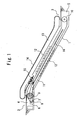
- Figure 1 is a side view showing a general configuration of an escalator.
- symbol 1 denotes a truss set between the adjacent upper and lower floors to carry the dead load of escalator and a live load
- 2 denotes an upper landing entrance
- 3 denotes a lower landing entrance
- 4 denotes an top truss space that consists of a space formed in an upper end portion of the truss 1 and is arranged under the upper landing entrance
- 5 denotes a bottom truss space that consists of a space formed in a lower end portion of the truss 1 and is arranged under the lower landing entrance 3.
- Symbol 6 denotes a driving machine provided in the top truss space 4
- 7 denotes a driving sprocket provided rotatably in the top truss space
- 8 denotes an endless driving chain set around the output shaft of the driving machine 6 and the driving sprocket 7 to transmit the driving force of the driving machine 6 to the driving sprocket
- 9 denotes an upper step sprocket that is provided on the rotating shaft of the driving sprocket 7 and rotates in association with the driving sprocket 7
- 10 denotes a lower step sprocket provided rotatably in the bottom truss space 5
- 11 denotes an endless step chain set around the upper step sprocket 9 and the lower step sprocket 10.
- symbol 12 denotes a step that is provided on each of step shafts (not shown) attached to the step chain 11 at a fixed intervals and circulatingly moves between the upper landing entrance 2 and the lower landing entrance 3 in association with the step chain 11 moved by the driving force of the driving machine 6
- 13 denotes a balustrade that is erected at both sides in the lengthwise direction of the truss 1 and is arranged at both sides of the step 12
- 14 denotes a handrail that is supported on the balustrade 13 and is moved circulatingly between the upper landing entrance 2 and the lower landing entrance 3 by being driven by a handrail driving unit 15 so that the upper end portion synchronizes with the passenger side of the step
- 16 denotes a lighting fixture that is provided on the truss 1 and is arranged over the lengthwise direction of the truss 1 under the passenger side of the step 12 and over the return side thereof.
- Figure 1 shows some of the steps 12 provided on the step chain 11.
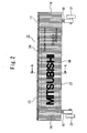
- Figure 2 is a front view of an escalator step in example 1 of the present invention
- Figure 3 is a plan view of the escalator step
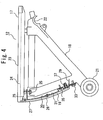
- Figure 4 is a side view thereof
- Figure 5 is a view taken in the direction of the arrows along the line A-A of the escalator step shown in Figure 2 .
- the step 12 includes a step tread 17 on which a passenger of the escalator gets when moving between the upper landing entrance 2 and the lower landing entrance 3, a pair of brackets 18 that are arranged at both sides in the lengthwise direction under the step tread 17 to support the step tread 17 from the downside, a riser 19 corresponding to the riser in the inclined portion of escalator, and a metallic reinforcing member 20 for attaching the riser 19 to the brackets 18.
- a step roller 21 is rotatably provided in the lower part on the riser 19 side, and a connecting portion 22 connected to the step shaft is provided in the upper part on the anti-riser 19 side.
- the paired step rollers 21 and driving rollers (not shown) provided in both end portions of the step shaft roll on the transfer rails (not shown) provided in the truss 1, by which the step 12 is roundingly moved by being guided.
- step tread 17 a step tread made by aluminum die casting, which has been used generally, a step tread partially made of a resin, or the like is used.
- a step tread partially made of a resin fiber-reinforced plastic (hereinafter referred to as "FRP") is used in a portion including a tread 23, and on the back side thereof, a metallic reinforcing material for securing predetermined strength and rigidity required by the step tread 17 is provided.
- FRP fiber-reinforced plastic
- cleats 24 having the long side thereof in the travelling direction of the step 12 are formed to prevent slip and to prevent the passenger's foot from being caught at the upper landing entrance 2 and the lower landing entrance 3.
- the bracket 18 is manufactured of an aluminum material by aluminum alloy die casting or aluminum casting from the viewpoint of the weight, strength, cost, etc. thereof.
- the bracket 18 has, for example, a substantially triangular ring shape, and the step tread 17 is fasteningly fixed to the upper part of the bracket 18 with a plurality of bolts 25.
- the step tread 17 may be fixed by using both of the bolts 25 and an epoxy resin based elastic adhesive.
- the riser 19 is manufactured of FRP as a whole, takes a thin plate shape, and has predetermined translucency (for example, semi-transparency).
- a surface 26 of the riser 19 is curved so as to take a convex shape in side view, and the riser 19 is arranged so as to extend downward from one side edge of the long side of the step tread 17.
- cleats 27 engaging with the cleats 24 formed on the tread 23 of the step 12 arranged on the one-step lower side are formed, so that when the steps 12 arranged in the front and rear direction move relatively in the up and down direction, the passenger's foot is prevented from being caught between the steps 12.
- the cleats 27 of the riser 19 are formed of a textile composite material formed by injection molding of resin using fibers braided three-dimensionally as a base material for securing enough strength and rigidity.
- resin to be injection molded for example, epoxy acrylate resin having fire resistance, flowability, and hardenability (production efficiency) necessary as the function of the step 12 is used.
- the metallic reinforcing member 20 is provided between and beyond the brackets 18 at both sides, and the riser 19 is fixed to this metallic reinforcing member 20 and thus supported on the brackets 18.
- Figure 6 is a front view showing the construction of the metallic reinforcing member in example 1 of the present invention, showing a state in which the riser 19 is removed from the step 12 shown in Figure 2 .
- the metallic reinforcing member 20 includes an upper reinforcement 28 formed of a sheet material, a lower reinforcement 29, and side reinforcements 30 and 31.
- the upper reinforcement 28 is provided between and beyond the upper parts of the brackets 18, and is arranged so as to face to the back surface upper edge portion of the riser 19.
- the lower reinforcement 29 is provided between and beyond the lower parts of the brackets 18, and is arranged so as to face to the back surface lower edge portion of the riser 19.
- the side reinforcement 30 is provided on one-side bracket 18.
- the side reinforcement 30 is arranged between one-side end portion of the upper reinforcement 28 and one-side end portion of the lower reinforcement 29, and is also arranged so as to face to the back surface one-side edge portion of the riser 19.
- the side reinforcement 31 is provided on the other-side bracket 18.
- the side reinforcement 31 is arranged between the other-side end portion of the upper reinforcement 28 and the other-side end portion of the lower reinforcement 29, and is also arranged so as to face to the other-side edge portion of the back surface of the riser 19.
- the metallic reinforcing member 20 has a substantially rectangular ring shape as a whole as viewed from the surface 26 side of the riser 19, and is constructed so as to face to the back surface peripheral edge portion of the riser 19.
- the riser 19 and the metallic reinforcing member 20 the predetermined strength and rigidity as the step 12 is secured.
- an opening 32 is formed between the brackets 18 at both sides, the opening 32 having a substantially rectangular shape with a width W and a height H as viewed from the surface 26 side of the riser 19.
- the riser 19 is provided on the metallic reinforcing member 20 so as to cover this opening 32.
- the portion facing to the opening 32 of the riser 19 has no reinforcements and obstacles on the back surface side thereof so that some of light passing through the opening 32 of the metallic reinforcing member 20, such as light from the lighting fixture 16, can transmit from the back surface side to the surface 26 side of the riser 19.
- the width W of the opening 32 is set so as to secure the distance between the brackets 18, and the height H is set so as to be as large as possible to provide the predetermined strength and rigidity as the step 12.
- the opening 32 in example 1 has a substantially rectangular shape, the shape etc. of the opening 32 is not subject to any restriction.
- the opening 32 means a portion in which the metallic reinforcing member 20 is not arranged as viewed from the surface 26 side of the riser 19.
- the reinforcements 28 to 31 from the viewpoint of weight, material strength, cost, and the like, for example, an aluminum casting, die-cast product, and extruded product are suitable in addition to the sheet material, and a square pipe and a product having a cross section of a hat shape, channel shape, and other shapes can be used.
- the reinforcements 28 to 31 can be formed of stainless steel to make the shapes thereof compact or to further make the opening 32 larger.
- the reinforcements 28 to 31 are fixed to the brackets 18 by using a plurality of bolts 25, 33 to 37 as shown in Figures 4 and 6 .
- the reinforcements 28 to 31 may be fixed by using both of the bolts 25, 33 to 37 and an epoxy resin based elastic adhesive.
- Symbol 38 denotes a film-shaped indicating element affixed to the back surface consisting of a smooth and curved surface of the riser 19.
- the indicating element 38 indicates indication content so as to be visible from the surface 26 side of the riser 19.
- Figure 7 is a front view of the indicating element in example 1 of the present invention
- Figure 8 is a side view of the indicating element.
- the indicating element 38 is formed by printing arbitrary patterns, characters, and the like on a back surface 38a of, for example, a PET film having a thickness of 100 ⁇ m, and is directly fixed to the back surface of the riser 19 by an adhesive applied to a front surface 38b thereof.
- the indicating element 38 is formed so that the width W1 thereof is equal to or somewhat greater than the width W of the opening 32 and the height H1 thereof is equal to or somewhat greater than the height H of the opening 32.
- the indicating element 38 is affixed to the back surface of the riser 19, and is arranged over the whole of the opening 32 in the state in which the riser 19 is installed to the metallic reinforcing member 20.
- the indicating element 38 has sufficient heat resistance, cold resistance, oil resistance, and durability so as to be consistent with the service environment of the step 12 for the escalator.
- an adhesive that can be peeled and has sufficient durability and stickiness so as to be consistent with the materials of the riser 19 and the indicating element 38 is used. Thereby, the work for reaffixing or replacing the indicating element 38 can be made easy, and also the riser 19 can be reused to reduce the environmental load.
- the indicating element 38 is adhesively fixed to the riser 19 in an arbitrary mode: for example, the adhesive is applied to the whole of the front surface 38b of the indicating element 38 so as to withstand the long-term use, or the adhesive is applied to only the peripheral edge portion of the front surface 38b of the indicating element 38 to facilitate the replacing work.
- the patterns etc. of the indicating element 38 adhesively fixed to the back surface of the riser 19 are allowed to emerge, so that the patterns etc. of the indicating element 38 can be indicated more vividly to the escalator passengers and persons standing around the escalator.
- the indicating element 38 is adhesively fixed to the back surface of the riser 19 by applying the adhesive to the whole of the front surface 38b of the indicating element 38, no gap is produced between the riser 19 and the indicating element 38, so that the patterns etc. of the indicating element 38 are allowed to emerge more vividly on the front surface 26 of the riser 19.
- the lighting fixture 16 is made up of, for example, a fluorescent lamp set between the members of the truss 1 and a stabilizer provided in the truss 1.
- the lighting illuminance within the truss 1 is arbitrary. However, sufficient illuminance can be obtained by arranging many fluorescent lamps in two rows on the right- and left-hand sides in the lengthwise direction of the truss 1.
- Figures 9 and 10 are side views for explaining the assembling procedure for the escalator step in example 1 of the present invention.
- the step tread 17 is fasteningly fixed to upper mounting surfaces 18a of both of the brackets 18 arranged at a predetermined interval by using the bolts 25.
- the bolts 25 are tightened in the state in which a lower side 28a of the upper reinforcement 28, the upper side of the side reinforcement 30, and an upper side 31a of side reinforcement 31 are held between a mounting portion 17a of the step tread 17 formed with a screw hole in which the bolt 25 is threadedly fitted and the upper mounting surfaces 18a of the brackets 18, by which the upper reinforcement 28 and the upper ends of the side reinforcements 30 and 31 are fixed to each other.
- the upper reinforcement 28 in which the vertical width of a portion facing to the riser 19 is narrow is attached to the bracket 18 by the fixing of the lower side 28a only.
- the upper reinforcement 28 shown in Figure 9 secures predetermined strength and rigidity by bending the upper side also to the anti-riser 19 side.
- the side reinforcement 31 in which the vertical width of a portion facing to the riser 19 is wide is fasteningly fixed to the other-side bracket 18 by fastening a concave portion 31b provided in the lower end portion of the side reinforcement 31 to the bracket 18 by using a bolt 35.
- a concave portion in the lower end portion of the side reinforcement 30 is fixed to the one-side bracket 18 by using a bolt 34.
- both of the end portions of the lower reinforcement 29 are fasteningly fixed to both of the brackets 18 by using the bolts 33, and the other-side end portion of an upper side 29a thereof bent to the anti-riser 19 side is fasteningly fixed to a lower side 31c of the side reinforcement 31 arranged so as to face to the upper side 29a of the lower reinforcement 29 by using the bolts 37.
- a mounting nut 29b may be fixed in advance to the other-side end portion of the upper side 29a of the lower reinforcement 29.
- one-side end portion of the upper side 29a is fasteningly fixed to the lower side of the side reinforcement 30 arranged so as to face to the upper side 29a by using a bolt 36.
- the step tread 17, the upper reinforcement 28, and the lower reinforcement 29 are connected between both of the brackets 18 arranged at the right and left, and are integrated firmly. Also, in the above-described assembled state, the substantially rectangularly shaped opening 32 rimmed with the reinforcements 28 to 31 is formed.
- the riser 19 since the surface 26 side of the riser 19 is manufactured of translucent FRP, a good appearance can be given to the riser 19. Therefore, the riser 19 itself serves as an indicating means. For example, an advertisement such as a guidance in a shop and a logo is displayed by the indicating element 38.
- the riser 19 can be used for various applications: for example, the riser 19 can play a role as a part of interior so as to match the escalator with the building, or the riser 19 can be used as an attention exciting means for the safety of escalator by lightening the passenger's feet. Also, comparing with the conventional example, since the whole of the surface 26 of the riser 19 is formed of FRP, there is offered an advantage that there is no fear of color loss and marred appearance when the riser 19 is used for many years.
- the riser portion requires predetermined strength and rigidity, so that if the whole thereof is attempted to be manufactured of FRP, the need for greatly increasing the thickness thereof arises and the cost increases, and also it becomes difficult to achieve the stability of dimensional accuracy.
- the metallic reinforcing member 20 is provided between and beyond the brackets 18 arranged in the right and left direction, and the FRP-made riser 19 is fixed to the metallic reinforcing member 20, so that the riser 19 can be formed by a thin sheet member, and hence the production efficiency can be improved and the cost can be reduced.
- the predetermined strength and rigidity can be secured by a simple construction. Also, as described above, by fixing the parts by using fasteners such as screws and bolts and an adhesive, the reliability of the step 12 can be secured.
- the riser 19 does not require high wear resistance unlike the tread 23 of the step tread 17, which is always treaded down by the passenger. Further, since the riser 19 does not correspond to a portion on which the passenger gets, the performance of preventing slip, which is required by the tread 23 of the step tread 17, is also not required. Inversely, from the viewpoint of preventing the passenger's foot from being caught between the steps 12, a low friction coefficient is required. Therefore, the surface of FRP material for the riser 19 need not be coated to obtain improved wear resistance and high friction coefficient. Therefore, if only the riser 19 is formed of FRP, the lightweight and improved appearance can be attained without waste.
- step 12 having the above-described construction is used for an escalator
- all of the steps may be the steps 12 having the above-described construction.
- some of the steps may be the steps 12 having the above-described construction, and other steps may be steps provided with the conventional aluminum die-cast riser.
- any configuration can be provided: for example, by affixing the indicating elements 38 having no translucency to the back surfaces of the risers 19 of some steps, only some steps are provided with any indication.
- the riser can be provided with a unique appearance, whereby the riser can be used for various applications. Also, by supporting the FRP-made riser on the brackets at both sides via the metallic reinforcing member, the predetermined strength and rigidity can be secured, and also by constructing the riser into a thin plate shape, improved production efficiency and low cost can be achieved.
Landscapes
- Escalators And Moving Walkways (AREA)
Applications Claiming Priority (1)
| Application Number | Priority Date | Filing Date | Title |
|---|---|---|---|
| PCT/JP2006/307072 WO2007113897A1 (ja) | 2006-04-03 | 2006-04-03 | エスカレータのステップとそれを備えたエスカレータ |
Publications (3)
| Publication Number | Publication Date |
|---|---|
| EP2003083A2 true EP2003083A2 (de) | 2008-12-17 |
| EP2003083A9 EP2003083A9 (de) | 2009-04-08 |
| EP2003083A4 EP2003083A4 (de) | 2018-01-24 |
Family
ID=38563170
Family Applications (1)
| Application Number | Title | Priority Date | Filing Date |
|---|---|---|---|
| EP06731020.1A Withdrawn EP2003083A4 (de) | 2006-04-03 | 2006-04-03 | Rolltreppenstufe und rolltreppe damit |
Country Status (5)
| Country | Link |
|---|---|
| EP (1) | EP2003083A4 (de) |
| JP (1) | JP5076905B2 (de) |
| KR (1) | KR100955562B1 (de) |
| CN (1) | CN101163637B (de) |
| WO (1) | WO2007113897A1 (de) |
Cited By (2)
| Publication number | Priority date | Publication date | Assignee | Title |
|---|---|---|---|---|
| EP2537792A3 (de) * | 2011-06-24 | 2013-02-20 | ThyssenKrupp Elevator Innovation Center S.A. | Rolltreppenstufe |
| CN104071660A (zh) * | 2014-07-17 | 2014-10-01 | 庄可香 | 用于电梯/自动扶梯梯级的多媒体显示系统及制造方法 |
Families Citing this family (4)
| Publication number | Priority date | Publication date | Assignee | Title |
|---|---|---|---|---|
| JP2011073815A (ja) * | 2009-09-30 | 2011-04-14 | Hitachi Ltd | 乗客コンベア用ステップ及びその製造方法 |
| JP5189611B2 (ja) * | 2010-03-10 | 2013-04-24 | 株式会社日立製作所 | 乗客コンベア |
| JP2014061974A (ja) * | 2012-09-21 | 2014-04-10 | Hitachi Ltd | 乗客コンベアのステップ及びこれを用いた乗客コンベア |
| KR102067754B1 (ko) * | 2015-11-17 | 2020-01-17 | 미쓰비시덴키 가부시키가이샤 | 승객 컨베이어 |
Family Cites Families (7)
| Publication number | Priority date | Publication date | Assignee | Title |
|---|---|---|---|---|
| JPS61295987A (ja) * | 1985-06-21 | 1986-12-26 | 三菱電機株式会社 | 乗客コンベア装置 |
| JPS61248892A (ja) * | 1985-04-23 | 1986-11-06 | 三菱電機株式会社 | エスカレ−タの表示装置 |
| NZ238537A (en) * | 1991-06-13 | 1994-05-26 | Escalator Advertising Ltd | Escalator step with advertising sign |
| NZ248337A (en) * | 1993-08-05 | 1995-11-27 | Escalator Advertising Ltd | Escalator step with transparent cleated cover plate engageable on step riser mounting plate |
| JPH1045365A (ja) * | 1996-08-05 | 1998-02-17 | Toshiba Elevator Technos Kk | 乗客コンベアの踏板装置及びその清掃方法 |
| JP3935699B2 (ja) * | 2001-10-10 | 2007-06-27 | 株式会社日立製作所 | 乗客コンベアの踏段体 |
| JP4287701B2 (ja) * | 2003-06-04 | 2009-07-01 | 三菱電機株式会社 | エスカレータの踏段 |
-
2006
- 2006-04-03 KR KR1020077017737A patent/KR100955562B1/ko not_active Expired - Fee Related
- 2006-04-03 EP EP06731020.1A patent/EP2003083A4/de not_active Withdrawn
- 2006-04-03 WO PCT/JP2006/307072 patent/WO2007113897A1/ja not_active Ceased
- 2006-04-03 JP JP2007545773A patent/JP5076905B2/ja not_active Expired - Fee Related
- 2006-04-03 CN CN2006800129957A patent/CN101163637B/zh not_active Expired - Fee Related
Non-Patent Citations (1)
| Title |
|---|
| See references of WO2007113897A1 * |
Cited By (4)
| Publication number | Priority date | Publication date | Assignee | Title |
|---|---|---|---|---|
| EP2537792A3 (de) * | 2011-06-24 | 2013-02-20 | ThyssenKrupp Elevator Innovation Center S.A. | Rolltreppenstufe |
| ES2411982R1 (es) * | 2011-06-24 | 2013-08-09 | Thyssenkrupp Elev Innovation | Peldano para escaleras mecanicas y procedimiento de fabricacion |
| CN104071660A (zh) * | 2014-07-17 | 2014-10-01 | 庄可香 | 用于电梯/自动扶梯梯级的多媒体显示系统及制造方法 |
| CN104071660B (zh) * | 2014-07-17 | 2016-05-11 | 庄可香 | 用于电梯/自动扶梯梯级的多媒体显示系统及制造方法 |
Also Published As
| Publication number | Publication date |
|---|---|
| KR20080003772A (ko) | 2008-01-08 |
| CN101163637A (zh) | 2008-04-16 |
| EP2003083A4 (de) | 2018-01-24 |
| JP5076905B2 (ja) | 2012-11-21 |
| JPWO2007113897A1 (ja) | 2009-08-13 |
| EP2003083A9 (de) | 2009-04-08 |
| KR100955562B1 (ko) | 2010-04-30 |
| WO2007113897A1 (ja) | 2007-10-11 |
| CN101163637B (zh) | 2011-04-06 |
Similar Documents
| Publication | Publication Date | Title |
|---|---|---|
| KR101495379B1 (ko) | 운반 장치의 발판 유닛을 위한 계단 지지부 또는 판 지지부, 발판 유닛 및 운반 장치 | |
| JP5121180B2 (ja) | エスカレータ | |
| US9617122B2 (en) | Pallet for a moving walk or step for an escalator | |
| HUT64913A (en) | Advertising fitting | |
| EP2003083A9 (de) | Rolltreppenstufe und rolltreppe damit | |
| AU2008309740A1 (en) | Step for escalator or plate for travelator, and escalator or travelator and method for production | |
| US5411127A (en) | Escalators | |
| GB2121748A (en) | Reconstruction method for improving man conveyor | |
| CN87105989A (zh) | 自动扶梯台阶的侧面板 | |
| KR100426705B1 (ko) | 에스컬레이터계단의복합덮개및이의제조방법 | |
| EP1828030B1 (de) | Handlaufführung für personenbeförderer | |
| US20200095097A1 (en) | Variable speed moving walkway systems | |
| JP2011063327A (ja) | 乗客コンベア | |
| US8511455B2 (en) | Escalator step | |
| JPH07238638A (ja) | アルミ型材からなる支柱の構造 | |
| JP4287701B2 (ja) | エスカレータの踏段 | |
| JP2012001290A (ja) | 乗客コンベア | |
| JP3833049B2 (ja) | 乗客コンベアの踏段 | |
| WO2021217229A1 (en) | Water slide segment incorporating wear layer and related methods | |
| EP1751047A2 (de) | Fahrsteig, fahrrampe oder aufzug | |
| CN216684627U (zh) | 一种具有盲道提示功能的踏板及安装结构 | |
| JP2001340658A (ja) | ウオータースライド構造 | |
| KR19990035786U (ko) | 광고판 장착구조를 구비한 에스컬레이터 스텝 | |
| CN200999569Y (zh) | 固定驱动门装饰扣条装置 | |
| CN210064852U (zh) | 一种便于拆装扶手的电梯轿厢 |
Legal Events
| Date | Code | Title | Description |
|---|---|---|---|
| PUAI | Public reference made under article 153(3) epc to a published international application that has entered the european phase |
Free format text: ORIGINAL CODE: 0009012 |
|
| 17P | Request for examination filed |
Effective date: 20070719 |
|
| AK | Designated contracting states |
Kind code of ref document: A2 Designated state(s): DE |
|
| PUAB | Information related to the publication of an a document modified or deleted |
Free format text: ORIGINAL CODE: 0009199EPPU |
|
| RBV | Designated contracting states (corrected) |
Designated state(s): DE |
|
| RBV | Designated contracting states (corrected) |
Designated state(s): DE |
|
| DAX | Request for extension of the european patent (deleted) | ||
| RA4 | Supplementary search report drawn up and despatched (corrected) |
Effective date: 20180102 |
|
| RIC1 | Information provided on ipc code assigned before grant |
Ipc: B66B 23/12 20060101AFI20171219BHEP Ipc: B66B 31/00 20060101ALI20171219BHEP |
|
| STAA | Information on the status of an ep patent application or granted ep patent |
Free format text: STATUS: EXAMINATION IS IN PROGRESS |
|
| 17Q | First examination report despatched |
Effective date: 20210617 |
|
| STAA | Information on the status of an ep patent application or granted ep patent |
Free format text: STATUS: THE APPLICATION IS DEEMED TO BE WITHDRAWN |
|
| 18D | Application deemed to be withdrawn |
Effective date: 20231101 |