EP2003234A1 - Motte de tresse pour une machine à tresser - Google Patents
Motte de tresse pour une machine à tresser Download PDFInfo
- Publication number
- EP2003234A1 EP2003234A1 EP08009990A EP08009990A EP2003234A1 EP 2003234 A1 EP2003234 A1 EP 2003234A1 EP 08009990 A EP08009990 A EP 08009990A EP 08009990 A EP08009990 A EP 08009990A EP 2003234 A1 EP2003234 A1 EP 2003234A1
- Authority
- EP
- European Patent Office
- Prior art keywords
- holder
- guide element
- braiding
- braid
- braiding machine
- Prior art date
- Legal status (The legal status is an assumption and is not a legal conclusion. Google has not performed a legal analysis and makes no representation as to the accuracy of the status listed.)
- Granted
Links
- 238000009954 braiding Methods 0.000 title claims abstract description 61
- 238000009941 weaving Methods 0.000 claims 1
- 230000036316 preload Effects 0.000 abstract description 3
- 230000033001 locomotion Effects 0.000 description 28
- 238000011161 development Methods 0.000 description 4
- 230000018109 developmental process Effects 0.000 description 4
- 230000006835 compression Effects 0.000 description 3
- 238000007906 compression Methods 0.000 description 3
- 230000015572 biosynthetic process Effects 0.000 description 2
- 239000002131 composite material Substances 0.000 description 2
- 238000007665 sagging Methods 0.000 description 2
- 241000085356 Aristostomias tittmanni Species 0.000 description 1
- 241000047428 Halter Species 0.000 description 1
- 238000006243 chemical reaction Methods 0.000 description 1
- 238000010276 construction Methods 0.000 description 1
- 230000000694 effects Effects 0.000 description 1
- 210000000056 organ Anatomy 0.000 description 1
- 230000000630 rising effect Effects 0.000 description 1
- 238000007493 shaping process Methods 0.000 description 1
Images

Classifications
-
- D—TEXTILES; PAPER
- D04—BRAIDING; LACE-MAKING; KNITTING; TRIMMINGS; NON-WOVEN FABRICS
- D04C—BRAIDING OR MANUFACTURE OF LACE, INCLUDING BOBBIN-NET OR CARBONISED LACE; BRAIDING MACHINES; BRAID; LACE
- D04C3/00—Braiding or lacing machines
- D04C3/02—Braiding or lacing machines with spool carriers guided by track plates or by bobbin heads exclusively
- D04C3/34—Beater, or beat-up, mechanisms
-
- D—TEXTILES; PAPER
- D04—BRAIDING; LACE-MAKING; KNITTING; TRIMMINGS; NON-WOVEN FABRICS
- D04C—BRAIDING OR MANUFACTURE OF LACE, INCLUDING BOBBIN-NET OR CARBONISED LACE; BRAIDING MACHINES; BRAID; LACE
- D04C3/00—Braiding or lacing machines
- D04C3/02—Braiding or lacing machines with spool carriers guided by track plates or by bobbin heads exclusively
- D04C3/38—Driving-gear; Starting or stopping mechanisms
-
- D—TEXTILES; PAPER
- D04—BRAIDING; LACE-MAKING; KNITTING; TRIMMINGS; NON-WOVEN FABRICS
- D04C—BRAIDING OR MANUFACTURE OF LACE, INCLUDING BOBBIN-NET OR CARBONISED LACE; BRAIDING MACHINES; BRAID; LACE
- D04C3/00—Braiding or lacing machines
- D04C3/48—Auxiliary devices
Definitions
- the invention relates to a Flechtscholle for a braiding, with a guide element for the subtracted mesh, which guide element is held in a holder, which is associated with a trigger for a stoppage of the braiding machine.
- the so-called braiding point is fixed.
- the threads drawn from the individual bobbins of a braiding machine converge.
- the Flechtscholle has a guide element through which the braided product is withdrawn continuously.
- the holder holding the guide can be the quality of the braid produced both monitor and influence.
- a knot in one of the tapered yarns may thicken the braid so that it can only be pulled off by overcoming a higher resistance by the guide element of the Flechtscholle.
- the guide element is held with a holder which is movable relative to the stationary machine frame of the braiding machine.
- the resistance of the braid pulled off by the guide element can be converted into a movement, by means of which the trigger can be actuated for an interruption of operation of the braiding machine.
- the interruption of operation can and should take place in knots or loops as well as torn thread or expired coil, the former leads to lifting the Flechtscholle in the withdrawal direction by the guide element and the latter to the fall of the guide element or the Flechtscholle relative to the machine frame of the braiding machine.
- forces acting on the guide element acting more or less transversely to the take-off direction of the braid may occur, for example, in the case of a stiff clapper or stiff coil, which may likewise have a disadvantageous effect on the quality of the braid produced and which likewise expediently trigger an interruption of operation of the braiding machine should.
- Guide elements are subject to wear and must be replaced more or less frequently, which also requires business interruptions.
- the triggering of the business interruption can be done mechanically.
- braid as well as for the mentioned, known braid is provided as the operation interrupting organ, an electrical switch.
- the triggering of the business interruption must be adjustable, including the vanes are held in a respective holder with corresponding adjusting elements, such as springs, clamping screws and the like. For each replacement of a guide element, for example, during wear or machine conversion to other braids, therefore complicated and usually tedious adjustment work is required to get back to an optimal trigger point of the interruption of operation for the respective braid on each braiding machine.
- a swivel bracket may, for example, be bent from wire so that it extends in front of the lower opening edge of the guide element located in the holder and ends in the actuation region of a tripping device for the interweaving machine.
- the invention has the object of providing a braid in such a way that setting work for obtaining an optimal trigger point for a stoppage of the braiding machine can be reduced, so that a reduction of the necessary downtime is possible.
- a braid for a braiding machine with a guide element for the braid to be subtracted, which guide is associated with a holder, which is assigned a trigger for an interruption of the braiding machine, according to the invention is characterized in that the holder, aligned about a transverse to the drawing direction of the braid movable first axis, is hinged to a holding body, that the holding body to a aligned in the withdrawal direction of the mesh second axis is hinged to the braiding and that the trigger is a stationary held on the braiding electrical switch, which is a spring-biased actuating tappet has, which projects against a plunger deflecting part, which is arranged on a side facing the actuating plunger side of the holder.
- the holder By the articulation of the guide element receiving holder to a holding body, the holder can move relative to the holding body.
- forces for example, lead to lifting of the holder or abruptly falling withdrawal forces, for example, when the braid point sagging, by slipping the braid to be subtracted on the pulley of a braiding machine, are converted into a movement of the holder about the first axis, via which it is articulated on the holding body.
- the holding body is articulated to a aligned in the withdrawal direction of the mesh second axis movable on the machine frame of the braiding machine, the quality of the braid negative influencing lateral forces in movements of the braid can be implemented around this second axis and thereby also trigger a business interruption.
- the trigger is particularly advantageous a stationary held on the braiding electrical switch with a spring biased actuating tappet.
- Such switches are inexpensive serial parts and work relatively reliable.
- the actuating plunger protrudes against a plunger deflecting part, which is arranged on the holder, so that the actuating plunger with its associated spring preload can abut the plunger deflecting part constantly. This has the advantage that even slight movements of the holder relative to the holding body, or the holding body relative to the machine frame of the braiding machine, lead to a movement of the actuating plunger.
- the arrangement may also be made such that the spring-loaded actuating plunger protrudes into the path of movement of the plunger deflecting part, whereby the actuating plunger, when striking the plunger deflection member to the actuating plunger, executes the operational interrupting release movement.
- the actuating plunger when striking the plunger deflection member to the actuating plunger, executes the operational interrupting release movement.
- acting on a suitable control electronics sensors can be used.
- the support carrying the guide holder is hinged to a holding body and on the other hand, the holding body on the machine frame of the braiding machine, it is a feature essential to the invention, the Flechtscholle that it has a two-part body, the two parts of the body articulated connected to each other, such that the provided with the guide member of the body a movement about a direction transverse to the withdrawal direction of the guided braid aligned first axis can perform.
- the second element of the body, the holding body do not follow this movement; because it, or he is only articulated about a aligned in the withdrawal direction of the braid second axis on the braiding machine, in particular on the machine frame of the braiding machine articulated.
- the plunger deflection part is a pan-like depression formed in a plane surface of the holder.
- the actuating plunger can be held by the spring preload acting on it with the pan surface of the recess in abutment.
- Such a system can be adjusted or adjusted relatively easily.
- a corresponding curve-shaped shaping of the deflection part can also be provided.
- Each component which is capable of causing a longitudinal movement of the actuating plunger with a corresponding transverse movement to the longitudinal axis of the actuating plunger is thus suitable for a cooperation between the invention two-part jointed Flechtscholle and provided as a trigger electrical switch.
- the Flechtscholle is also characterized by the fact that the actuating plunger has a ball head located at its free end.
- a ball head is particularly suitable to implement movements of the plunger deflecting part, in particular when this is designed as a pan-like depression, in switching movements of the actuating plunger.
- the actuating plunger is always due to the ball head in a respective desired switching direction moves.
- Switching direction is usually a direction of movement in the linear longitudinal direction of the actuating plunger.
- microswitches known per se are applicable, for example.
- the guide element is designed as an insert which is held interchangeably in the holder.
- the holder is designed as a receptacle for use.
- An insert can be handled as a unit and can be replaced quickly if necessary.
- an insert may be formed so that it can be pulled out of the holder, or for replacement in the holder can be inserted.
- the insert is a sleeve of at least two juxtaposed half-shells.
- This embodiment as a split sleeve facilitates the replacement of such a launched guide, whereby the times are reduced for business interruptions.
- an advantageous embodiment of the braid according to the invention provides that the holder is composed of the guide element enclosing jaws.
- This embodiment is particularly advantageous for a guide element, which is in the form of a sleeve, which thus forms a unit received in the holder.
- the holder composed of the jaws enclosing the sleeve as guide element forms a receptacle into which the guide element can be inserted from one side, preferably from below, or can be pulled out downwards.
- At least a first jaw of the jaw enclosing the guide element is hinged to the holding body.
- the sleeve received in the holder, by which the guide element is formed is also movably articulated to the holder body.
- the ram deflection part which is arranged on a side facing the actuating tappet of the electrical switch side of the holder, also participate in the movements reported to the guide, which Flechtscholle around the transversely to, or in the withdrawal direction of the braid aligned axes executes.
- any movement of the plunger deflecting part can lead to a switching movement of the actuating plunger and thus to a stoppage of the braiding machine.
- the trip point for the stoppage can be adjusted by means of tension springs to a predetermined value.
- the design according to the invention also makes it possible, if appropriate, to replace a complete braid as a unit, which is adjusted accordingly before it is installed in the braiding machine for which it is intended. This is particularly advantageous if the Braiding machine to be changed to another type of braid to be produced.
- the holding body which forms a structural unit together with the holder hinged thereto, is simply removed from the component which forms the second axis oriented in the drawing-off direction of the braiding and which is installed on the machine frame of the braiding machine.
- the second axis can be realized by a hollow cylindrical bearing pin which engages in a correspondingly large bore in the holding body, so that the holding body is ultimately mounted on the bearing journal.
- the journal may for example also have a bracket, bracket or the like fastener, with which it can be attached to the braiding machine and on which also present as an electrical switch triggers can be mounted.
- At least one of the jaws, from which the holder is composed for the guide element has an actuatable locking bar, which can be brought into operative connection with the guide element.
- the actuatable Festsetzriegel has the advantage that a recorded, for example, in the holder guide element in the intended working position or operating position can be fixed and is also locked, while triggering the Festsetzriegels a simple disassembly of the guide element from the holder is possible.
- the locking bar is a sliding pin, which is received in a longitudinally displaceable manner in a bore in the holder.
- the bore extends approximately tangentially or secantially to the guide element forming sleeve.
- the push pin has a waist-like constricted pin portion, wherein the waist-like constriction is formed such that it congruates with the outer circumference of the sleeve when the slide pin is pushed into the corresponding sliding position along the bore.
- the slide pin is associated with a spring which holds the slide pin in a sliding position in which the present as a sleeve guide element is fixed in the holder.
- the guide element can be removed from the holder.
- the sliding pin After inserting a replacement sleeve, which also takes place when pushed against the spring force slide pin, the sliding pin is released so that it is pushed back by the spring acting on it in a position in which his waist-like constriction is no longer with the outer circumference of the sleeve or the Leitelemtent congruent, but now the sleeve is locked or fixed in the holder.
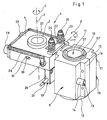
- Fig. 1 a view of a braid 1 is shown.
- the Flechtscholle 1 is a complete assembly on a hollow cylindrical bearing pin 2 to one in the withdrawal direction of the braid 6 (FIG. Fig. 2 ) aligned second axis 3 is movably articulated to the braiding machine not shown.
- the articulated to the braiding machine component of the unit, which the Flechtscholle forms, is the holding body 4, which thus movements, symbolized by the double arrow 5, to perform the second axis 3.
- a front, head-like part of the Flechtscholle 1 is designated 9 holder.
- the holder 9 forms together with the holding body 4, the braid 1.
- the holder 9 is, to a transverse to the withdrawal direction of the braid 6 not shown ( Fig. 2 ) aligned first axis 7 movable, hinged to the support body 4. He can thus perform oscillating up and down movements in the direction of the double arrow 8 about the first axis 7.
- the braid 6 is pulled off by a puller of the braiding machine, not shown, upwards.
- the braid 6 is formed in the braiding 132, which arises just below the braid 1 shown here, namely from bundled in the braiding monofilaments that run from coils sitting on the braiding in predetermined paths around the braided guided bobbins.
- the guide element 11 forming the sleeve 10 consists of two half-shells 37, 37 ', as indicated here.
- the sleeve has a lower collar flange 12 and may e.g. be inserted from below into a receptacle in the holder 9 until the collar flange 12 abuts against the opening edge of the receptacle in the holder 9. In this position, the guide element 11 accommodated in the holder 9, the sleeve 10, is fixed with the fixing bar 13 designed as a sliding pin 14.
- the holder 9 consists of two jaws 15, 16 which form a present as a sleeve 10 guide element 11 enclosing terminal, wherein the visible jaws 15, 16 by means not shown screws 17, 18th can be contracted. To replace the guide element 11, the screws 17, 18 can also be loosened, if necessary, to remove the loose jaw 15 from the fixed jaw 16 mounted on the axis 7.
- the trigger 19 is a trigger for a business interruption of the braiding machine, not shown designated.
- the trigger 19 is here an electrical switch 20, to which the indicated control line 21 is connected.
- the compression springs 22, 23 can be adjusted so that their action against the tension springs 26, 27 determines the trigger point at which a pivotal movement of the holder 9 about the axis 7 converts into an actuation of the electrical switch 20, which serves as a trigger 19 for a stoppage of the braiding machine.
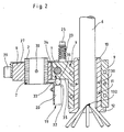
- Fig. 2 shows a sectional view of the Flechtscholle 1.
- the same components are designated by the same reference numerals as in Fig. 1 ,
- Fig. 2 indicated as the individual threads run into the sleeve 10 as a guide member 11 forming the braid point 132 and are withdrawn as a finished braid 6 from below.
- Fig. 2 illustrates that the guide element 11, for replacement, from below into a suitable receptacle in the holder 9 is inserted or can be pushed out downward, with pins or screws 130 can be used for fixing.
- Fig. 2 illustrates how the holder 9 can move around the first axis 7 with rising or falling braiding 132. This movement is used to initiate an interruption of operation of the braiding machine by means of the trigger 19 present here as an electrical switch 20.
- the actuating plunger 32 of the present as a trigger 19 electrical switch 20 projects with the located at its free end ball head 33 against a plunger deflection 34, which is here formed as a molded into a flat surface of the holder 9 pan-like recess 36.
- Fig. 2 indicates that the holder 9 is seated with a bore on the journal 2 and thus, together with the hinged on the first axis 7 to him holder 9, can perform rotational movements about the stationary bearing journal 2, for example, on the guide element 11th acting side forces, as they can occur in stiff bobbins or coils.
- These rotational movements of the holder 9 about an axis parallel to the withdrawal direction of the mesh 6 axis (second axis 3 in Fig. 1 ) causes a movement of the molded into the flat surface 35 pan-like depression, which leads to the deflection of the ball head 33 at the free end of the actuating plunger 32, and thus leads to triggering a stoppage of the braiding machine via the electrical switch 20.
- Fig. 3 shows a plan view of the holder. 9 Fig. 3 illustrates that the guide element 11 is a composite of two half-shells 37, 37 'sleeve 10.
- the guide element 11 is thus a component which is in a receptacle, e.g. a bore held in the holder 9 and is easily replaceable.
- the jaws enclosing the guide element are again denoted by 15 and 16.
- a Festsetzriegel 13 is provided for a quick change of the trained as an insert guide element 11 .
- This is designed as a sliding pin 14 which is received in a bore 38 in the holder 9, here its jaw 16, longitudinally displaceable.
- the bore 38 extends approximately tangentially or secant to the guide element 11 forming sleeve 10.
- the locking pin 13 formed as a sliding pin 14 has, as indicated here, a waist-like constricted pin portion 39, wherein the waist-like constriction is formed and arranged such that it congruates with the outer periphery of the sleeve 10 when the slide pin 14 is pushed into the corresponding sliding position along the bore 38. In this sliding position, the guide element 11 forming sleeve 10 can be removed from the holder 9. Guide element 11 and holder 9 are thus easily removable.
- the sliding pin 14 of the fixing bolt 13 is associated with a spring 40 which holds the sliding pin 14 in a sliding position, in which the sleeve 10 is fixed in the holder 9.
- This sliding position shows Fig. 3 ,
Landscapes
- Engineering & Computer Science (AREA)
- Textile Engineering (AREA)
- Braiding, Manufacturing Of Bobbin-Net Or Lace, And Manufacturing Of Nets By Knotting (AREA)
Applications Claiming Priority (1)
| Application Number | Priority Date | Filing Date | Title |
|---|---|---|---|
| DE200710027144 DE102007027144A1 (de) | 2007-06-13 | 2007-06-13 | Flechtscholle für eine Flechtmaschine |
Publications (2)
| Publication Number | Publication Date |
|---|---|
| EP2003234A1 true EP2003234A1 (fr) | 2008-12-17 |
| EP2003234B1 EP2003234B1 (fr) | 2012-05-30 |
Family
ID=39766863
Family Applications (1)
| Application Number | Title | Priority Date | Filing Date |
|---|---|---|---|
| EP20080009990 Not-in-force EP2003234B1 (fr) | 2007-06-13 | 2008-05-31 | Motte de tresse pour une machine à tresser |
Country Status (3)
| Country | Link |
|---|---|
| EP (1) | EP2003234B1 (fr) |
| DE (1) | DE102007027144A1 (fr) |
| ES (1) | ES2388794T3 (fr) |
Cited By (1)
| Publication number | Priority date | Publication date | Assignee | Title |
|---|---|---|---|---|
| CN115250815A (zh) * | 2022-08-01 | 2022-11-01 | 江苏省黄海农场有限公司 | 一种长青柳冬青造型苗培育架及其培育方法 |
Families Citing this family (1)
| Publication number | Priority date | Publication date | Assignee | Title |
|---|---|---|---|---|
| DE102004060179B4 (de) * | 2004-12-14 | 2009-11-05 | Continental Automotive Gmbh | Einspritzventil mit einem verbesserten Anschluss eines Anschlusssteckers |
Citations (1)
| Publication number | Priority date | Publication date | Assignee | Title |
|---|---|---|---|---|
| EP0498944A2 (fr) | 1991-02-09 | 1992-08-19 | AUGUST HERZOG MASCHINENFABRIK GmbH & CO. KG | Condenseur de tressage |
Family Cites Families (1)
| Publication number | Priority date | Publication date | Assignee | Title |
|---|---|---|---|---|
| AT107169B (de) * | 1925-07-09 | 1927-09-10 | Alfred Ing Roth | Schlingen- und Knotenfänger für Flechtmaschinen und für Vorrichtungen zum Überprüfen von Flechtwerk. |
-
2007
- 2007-06-13 DE DE200710027144 patent/DE102007027144A1/de not_active Withdrawn
-
2008
- 2008-05-31 ES ES08009990T patent/ES2388794T3/es active Active
- 2008-05-31 EP EP20080009990 patent/EP2003234B1/fr not_active Not-in-force
Patent Citations (1)
| Publication number | Priority date | Publication date | Assignee | Title |
|---|---|---|---|---|
| EP0498944A2 (fr) | 1991-02-09 | 1992-08-19 | AUGUST HERZOG MASCHINENFABRIK GmbH & CO. KG | Condenseur de tressage |
Cited By (2)
| Publication number | Priority date | Publication date | Assignee | Title |
|---|---|---|---|---|
| CN115250815A (zh) * | 2022-08-01 | 2022-11-01 | 江苏省黄海农场有限公司 | 一种长青柳冬青造型苗培育架及其培育方法 |
| CN115250815B (zh) * | 2022-08-01 | 2024-03-15 | 江苏省黄海农场有限公司 | 一种长青柳冬青造型苗培育架及其培育方法 |
Also Published As
| Publication number | Publication date |
|---|---|
| ES2388794T3 (es) | 2012-10-18 |
| DE102007027144A1 (de) | 2008-12-24 |
| EP2003234B1 (fr) | 2012-05-30 |
Similar Documents
| Publication | Publication Date | Title |
|---|---|---|
| DE1916580C3 (de) | Changier vorrichtung an Aufwickelvorrichtungen | |
| DE1710343C3 (de) | Webmaschine mit einer Schußfadenwechselvorrichtung zur Entnahme des Schußfadens von ortsfesten Vorratsspulen | |
| DE2750913C2 (de) | Verfahren und Vorrichtung zum Verbinden von Textilfäden | |
| EP3850133B1 (fr) | Machine à tisser avec un dispositif de sélection de la couleur des fils de trame | |
| DE2163140B2 (de) | Vorrichtung zum selbsttätigen Anspinnen an Ringspinnmaschinen | |
| EP2003234B1 (fr) | Motte de tresse pour une machine à tresser | |
| EP0293558B1 (fr) | Sélecteur de trame pour un métier à tisser | |
| DE3524727A1 (de) | Verfahren zum schussfadeneintrag bei schuetzenlosen webmaschinen durch ins webfach vorgeschobene und wieder zurueckgezogene, mit klemmvorrichtungen fuer den schussfaden ausgeruestete greifer | |
| CH617470A5 (fr) | ||
| DE1919533B2 (de) | Fadenwechselvorrichtung für Rundstrickmaschinen | |
| DE4132696C2 (de) | Breithalter und dessen Verwendung bei einer Webmaschine | |
| EP0310857B1 (fr) | Dispositif changeur de fil, notamment pour des métiers à tricoter | |
| DE19932484C1 (de) | Fadenliefergerät mit Fühlersperre | |
| DE2836717B2 (de) | Positive Fadenliefervorrichtung fur Textilmaschinen | |
| EP3785336B1 (fr) | Changeur d'outil, machine d'usinage, procédé de changement d'un outil | |
| EP0753618A2 (fr) | Blocage de fil | |
| DE2653488C2 (de) | Vorrichtung für Flachstrickmaschinen zum Abziehen einer Gestrickbahn | |
| DE2925694C2 (de) | Schußfadeneintragorgan einer schützenlosen Webmaschine | |
| DE258875C (fr) | ||
| DE60004603T2 (de) | Lösbare Haltevorrichtung für den Bremsträger in Fadenliefervorrichtungen von Textilmaschinen | |
| EP3401423B1 (fr) | Procédé de pressage d'un cylindre presseur contre un cylindre de traction ainsi que dispositif de traction | |
| DE2504577C3 (de) | Einrichtung zum Aufspulen | |
| DE1535643C2 (de) | Schußfaden Zwischenspeicher fur Webmaschinen mit feststehender Schuß faden Vorratsspule | |
| EP1082477A1 (fr) | Tendeur de fil | |
| DE2054788C3 (de) | Greiferpaar für den SchuBeintrag in einer Webmaschine |
Legal Events
| Date | Code | Title | Description |
|---|---|---|---|
| PUAI | Public reference made under article 153(3) epc to a published international application that has entered the european phase |
Free format text: ORIGINAL CODE: 0009012 |
|
| AK | Designated contracting states |
Kind code of ref document: A1 Designated state(s): AT BE BG CH CY CZ DE DK EE ES FI FR GB GR HR HU IE IS IT LI LT LU LV MC MT NL NO PL PT RO SE SI SK TR |
|
| AX | Request for extension of the european patent |
Extension state: AL BA MK RS |
|
| 17P | Request for examination filed |
Effective date: 20081205 |
|
| AKX | Designation fees paid |
Designated state(s): AT BE BG CH CY CZ DE DK EE ES FI FR GB GR HR HU IE IS IT LI LT LU LV MC MT NL NO PL PT RO SE SI SK TR |
|
| GRAP | Despatch of communication of intention to grant a patent |
Free format text: ORIGINAL CODE: EPIDOSNIGR1 |
|
| GRAS | Grant fee paid |
Free format text: ORIGINAL CODE: EPIDOSNIGR3 |
|
| GRAA | (expected) grant |
Free format text: ORIGINAL CODE: 0009210 |
|
| AK | Designated contracting states |
Kind code of ref document: B1 Designated state(s): AT BE BG CH CY CZ DE DK EE ES FI FR GB GR HR HU IE IS IT LI LT LU LV MC MT NL NO PL PT RO SE SI SK TR |
|
| REG | Reference to a national code |
Ref country code: GB Ref legal event code: FG4D Free format text: NOT ENGLISH |
|
| REG | Reference to a national code |
Ref country code: CH Ref legal event code: EP |
|
| REG | Reference to a national code |
Ref country code: AT Ref legal event code: REF Ref document number: 560126 Country of ref document: AT Kind code of ref document: T Effective date: 20120615 |
|
| REG | Reference to a national code |
Ref country code: IE Ref legal event code: FG4D Free format text: LANGUAGE OF EP DOCUMENT: GERMAN |
|
| REG | Reference to a national code |
Ref country code: DE Ref legal event code: R096 Ref document number: 502008007284 Country of ref document: DE Effective date: 20120726 |
|
| REG | Reference to a national code |
Ref country code: NL Ref legal event code: VDEP Effective date: 20120530 |
|
| REG | Reference to a national code |
Ref country code: ES Ref legal event code: FG2A Ref document number: 2388794 Country of ref document: ES Kind code of ref document: T3 Effective date: 20121018 |
|
| REG | Reference to a national code |
Ref country code: LT Ref legal event code: MG4D Effective date: 20120530 |
|
| PG25 | Lapsed in a contracting state [announced via postgrant information from national office to epo] |
Ref country code: SE Free format text: LAPSE BECAUSE OF FAILURE TO SUBMIT A TRANSLATION OF THE DESCRIPTION OR TO PAY THE FEE WITHIN THE PRESCRIBED TIME-LIMIT Effective date: 20120530 Ref country code: NO Free format text: LAPSE BECAUSE OF FAILURE TO SUBMIT A TRANSLATION OF THE DESCRIPTION OR TO PAY THE FEE WITHIN THE PRESCRIBED TIME-LIMIT Effective date: 20120830 Ref country code: LT Free format text: LAPSE BECAUSE OF FAILURE TO SUBMIT A TRANSLATION OF THE DESCRIPTION OR TO PAY THE FEE WITHIN THE PRESCRIBED TIME-LIMIT Effective date: 20120530 Ref country code: CY Free format text: LAPSE BECAUSE OF FAILURE TO SUBMIT A TRANSLATION OF THE DESCRIPTION OR TO PAY THE FEE WITHIN THE PRESCRIBED TIME-LIMIT Effective date: 20120530 Ref country code: IS Free format text: LAPSE BECAUSE OF FAILURE TO SUBMIT A TRANSLATION OF THE DESCRIPTION OR TO PAY THE FEE WITHIN THE PRESCRIBED TIME-LIMIT Effective date: 20120930 Ref country code: FI Free format text: LAPSE BECAUSE OF FAILURE TO SUBMIT A TRANSLATION OF THE DESCRIPTION OR TO PAY THE FEE WITHIN THE PRESCRIBED TIME-LIMIT Effective date: 20120530 |
|
| BERE | Be: lapsed |
Owner name: AUGUST HERZOG MASCHINENFABRIK G.M.B.H. & CO. KG Effective date: 20120531 |
|
| PG25 | Lapsed in a contracting state [announced via postgrant information from national office to epo] |
Ref country code: GR Free format text: LAPSE BECAUSE OF FAILURE TO SUBMIT A TRANSLATION OF THE DESCRIPTION OR TO PAY THE FEE WITHIN THE PRESCRIBED TIME-LIMIT Effective date: 20120831 Ref country code: LV Free format text: LAPSE BECAUSE OF FAILURE TO SUBMIT A TRANSLATION OF THE DESCRIPTION OR TO PAY THE FEE WITHIN THE PRESCRIBED TIME-LIMIT Effective date: 20120530 Ref country code: HR Free format text: LAPSE BECAUSE OF FAILURE TO SUBMIT A TRANSLATION OF THE DESCRIPTION OR TO PAY THE FEE WITHIN THE PRESCRIBED TIME-LIMIT Effective date: 20120530 Ref country code: SI Free format text: LAPSE BECAUSE OF FAILURE TO SUBMIT A TRANSLATION OF THE DESCRIPTION OR TO PAY THE FEE WITHIN THE PRESCRIBED TIME-LIMIT Effective date: 20120530 |
|
| PG25 | Lapsed in a contracting state [announced via postgrant information from national office to epo] |
Ref country code: MC Free format text: LAPSE BECAUSE OF NON-PAYMENT OF DUE FEES Effective date: 20120531 |
|
| REG | Reference to a national code |
Ref country code: CH Ref legal event code: PL |
|
| PG25 | Lapsed in a contracting state [announced via postgrant information from national office to epo] |
Ref country code: DK Free format text: LAPSE BECAUSE OF FAILURE TO SUBMIT A TRANSLATION OF THE DESCRIPTION OR TO PAY THE FEE WITHIN THE PRESCRIBED TIME-LIMIT Effective date: 20120530 Ref country code: EE Free format text: LAPSE BECAUSE OF FAILURE TO SUBMIT A TRANSLATION OF THE DESCRIPTION OR TO PAY THE FEE WITHIN THE PRESCRIBED TIME-LIMIT Effective date: 20120530 Ref country code: SK Free format text: LAPSE BECAUSE OF FAILURE TO SUBMIT A TRANSLATION OF THE DESCRIPTION OR TO PAY THE FEE WITHIN THE PRESCRIBED TIME-LIMIT Effective date: 20120530 Ref country code: RO Free format text: LAPSE BECAUSE OF FAILURE TO SUBMIT A TRANSLATION OF THE DESCRIPTION OR TO PAY THE FEE WITHIN THE PRESCRIBED TIME-LIMIT Effective date: 20120530 Ref country code: LI Free format text: LAPSE BECAUSE OF NON-PAYMENT OF DUE FEES Effective date: 20120531 Ref country code: CZ Free format text: LAPSE BECAUSE OF FAILURE TO SUBMIT A TRANSLATION OF THE DESCRIPTION OR TO PAY THE FEE WITHIN THE PRESCRIBED TIME-LIMIT Effective date: 20120530 Ref country code: CH Free format text: LAPSE BECAUSE OF NON-PAYMENT OF DUE FEES Effective date: 20120531 Ref country code: NL Free format text: LAPSE BECAUSE OF FAILURE TO SUBMIT A TRANSLATION OF THE DESCRIPTION OR TO PAY THE FEE WITHIN THE PRESCRIBED TIME-LIMIT Effective date: 20120530 |
|
| REG | Reference to a national code |
Ref country code: IE Ref legal event code: MM4A |
|
| PG25 | Lapsed in a contracting state [announced via postgrant information from national office to epo] |
Ref country code: PT Free format text: LAPSE BECAUSE OF FAILURE TO SUBMIT A TRANSLATION OF THE DESCRIPTION OR TO PAY THE FEE WITHIN THE PRESCRIBED TIME-LIMIT Effective date: 20121001 Ref country code: PL Free format text: LAPSE BECAUSE OF FAILURE TO SUBMIT A TRANSLATION OF THE DESCRIPTION OR TO PAY THE FEE WITHIN THE PRESCRIBED TIME-LIMIT Effective date: 20120530 Ref country code: BE Free format text: LAPSE BECAUSE OF NON-PAYMENT OF DUE FEES Effective date: 20120531 |
|
| PLBE | No opposition filed within time limit |
Free format text: ORIGINAL CODE: 0009261 |
|
| STAA | Information on the status of an ep patent application or granted ep patent |
Free format text: STATUS: NO OPPOSITION FILED WITHIN TIME LIMIT |
|
| GBPC | Gb: european patent ceased through non-payment of renewal fee |
Effective date: 20120830 |
|
| PG25 | Lapsed in a contracting state [announced via postgrant information from national office to epo] |
Ref country code: IE Free format text: LAPSE BECAUSE OF NON-PAYMENT OF DUE FEES Effective date: 20120531 |
|
| 26N | No opposition filed |
Effective date: 20130301 |
|
| REG | Reference to a national code |
Ref country code: DE Ref legal event code: R097 Ref document number: 502008007284 Country of ref document: DE Effective date: 20130301 |
|
| PG25 | Lapsed in a contracting state [announced via postgrant information from national office to epo] |
Ref country code: GB Free format text: LAPSE BECAUSE OF NON-PAYMENT OF DUE FEES Effective date: 20120830 Ref country code: MT Free format text: LAPSE BECAUSE OF FAILURE TO SUBMIT A TRANSLATION OF THE DESCRIPTION OR TO PAY THE FEE WITHIN THE PRESCRIBED TIME-LIMIT Effective date: 20120530 Ref country code: BG Free format text: LAPSE BECAUSE OF FAILURE TO SUBMIT A TRANSLATION OF THE DESCRIPTION OR TO PAY THE FEE WITHIN THE PRESCRIBED TIME-LIMIT Effective date: 20120830 |
|
| PG25 | Lapsed in a contracting state [announced via postgrant information from national office to epo] |
Ref country code: TR Free format text: LAPSE BECAUSE OF FAILURE TO SUBMIT A TRANSLATION OF THE DESCRIPTION OR TO PAY THE FEE WITHIN THE PRESCRIBED TIME-LIMIT Effective date: 20120530 |
|
| PG25 | Lapsed in a contracting state [announced via postgrant information from national office to epo] |
Ref country code: LU Free format text: LAPSE BECAUSE OF NON-PAYMENT OF DUE FEES Effective date: 20120531 |
|
| REG | Reference to a national code |
Ref country code: AT Ref legal event code: MM01 Ref document number: 560126 Country of ref document: AT Kind code of ref document: T Effective date: 20130531 |
|
| PG25 | Lapsed in a contracting state [announced via postgrant information from national office to epo] |
Ref country code: HU Free format text: LAPSE BECAUSE OF FAILURE TO SUBMIT A TRANSLATION OF THE DESCRIPTION OR TO PAY THE FEE WITHIN THE PRESCRIBED TIME-LIMIT Effective date: 20080531 |
|
| PG25 | Lapsed in a contracting state [announced via postgrant information from national office to epo] |
Ref country code: AT Free format text: LAPSE BECAUSE OF NON-PAYMENT OF DUE FEES Effective date: 20130531 |
|
| REG | Reference to a national code |
Ref country code: FR Ref legal event code: PLFP Year of fee payment: 9 |
|
| REG | Reference to a national code |
Ref country code: FR Ref legal event code: PLFP Year of fee payment: 10 |
|
| REG | Reference to a national code |
Ref country code: FR Ref legal event code: PLFP Year of fee payment: 11 |
|
| PGFP | Annual fee paid to national office [announced via postgrant information from national office to epo] |
Ref country code: IT Payment date: 20190521 Year of fee payment: 12 Ref country code: ES Payment date: 20190619 Year of fee payment: 12 Ref country code: DE Payment date: 20190329 Year of fee payment: 12 |
|
| PGFP | Annual fee paid to national office [announced via postgrant information from national office to epo] |
Ref country code: FR Payment date: 20190521 Year of fee payment: 12 |
|
| REG | Reference to a national code |
Ref country code: DE Ref legal event code: R119 Ref document number: 502008007284 Country of ref document: DE |
|
| PG25 | Lapsed in a contracting state [announced via postgrant information from national office to epo] |
Ref country code: FR Free format text: LAPSE BECAUSE OF NON-PAYMENT OF DUE FEES Effective date: 20200531 |
|
| PG25 | Lapsed in a contracting state [announced via postgrant information from national office to epo] |
Ref country code: DE Free format text: LAPSE BECAUSE OF NON-PAYMENT OF DUE FEES Effective date: 20201201 |
|
| REG | Reference to a national code |
Ref country code: ES Ref legal event code: FD2A Effective date: 20211006 |
|
| PG25 | Lapsed in a contracting state [announced via postgrant information from national office to epo] |
Ref country code: IT Free format text: LAPSE BECAUSE OF NON-PAYMENT OF DUE FEES Effective date: 20200531 |
|
| PG25 | Lapsed in a contracting state [announced via postgrant information from national office to epo] |
Ref country code: ES Free format text: LAPSE BECAUSE OF NON-PAYMENT OF DUE FEES Effective date: 20200601 |