EP2003246A1 - Rails encastrés pour véhicules sur rails et leur procédé de montage - Google Patents
Rails encastrés pour véhicules sur rails et leur procédé de montage Download PDFInfo
- Publication number
- EP2003246A1 EP2003246A1 EP08010678A EP08010678A EP2003246A1 EP 2003246 A1 EP2003246 A1 EP 2003246A1 EP 08010678 A EP08010678 A EP 08010678A EP 08010678 A EP08010678 A EP 08010678A EP 2003246 A1 EP2003246 A1 EP 2003246A1
- Authority
- EP
- European Patent Office
- Prior art keywords
- rail
- embedding
- anchor
- embedded
- holding
- Prior art date
- Legal status (The legal status is an assumption and is not a legal conclusion. Google has not performed a legal analysis and makes no representation as to the accuracy of the status listed.)
- Withdrawn
Links
- 238000000034 method Methods 0.000 title claims abstract description 7
- 238000003892 spreading Methods 0.000 claims description 16
- XLYOFNOQVPJJNP-UHFFFAOYSA-N water Substances O XLYOFNOQVPJJNP-UHFFFAOYSA-N 0.000 claims description 7
- 239000004566 building material Substances 0.000 claims description 6
- 239000013013 elastic material Substances 0.000 claims description 3
- 238000004873 anchoring Methods 0.000 claims description 2
- 238000005538 encapsulation Methods 0.000 claims 1
- 210000002414 leg Anatomy 0.000 description 7
- 230000008901 benefit Effects 0.000 description 6
- 239000004567 concrete Substances 0.000 description 6
- 239000000463 material Substances 0.000 description 6
- 238000004519 manufacturing process Methods 0.000 description 5
- 238000004382 potting Methods 0.000 description 4
- 150000001875 compounds Chemical class 0.000 description 3
- 238000007789 sealing Methods 0.000 description 3
- 230000007613 environmental effect Effects 0.000 description 2
- 238000005192 partition Methods 0.000 description 2
- 210000000689 upper leg Anatomy 0.000 description 2
- ABJSOROVZZKJGI-OCYUSGCXSA-N (1r,2r,4r)-2-(4-bromophenyl)-n-[(4-chlorophenyl)-(2-fluoropyridin-4-yl)methyl]-4-morpholin-4-ylcyclohexane-1-carboxamide Chemical compound C1=NC(F)=CC(C(NC(=O)[C@H]2[C@@H](C[C@@H](CC2)N2CCOCC2)C=2C=CC(Br)=CC=2)C=2C=CC(Cl)=CC=2)=C1 ABJSOROVZZKJGI-OCYUSGCXSA-N 0.000 description 1
- 240000003517 Elaeocarpus dentatus Species 0.000 description 1
- 241001669679 Eleotris Species 0.000 description 1
- 229910000831 Steel Inorganic materials 0.000 description 1
- 230000006978 adaptation Effects 0.000 description 1
- 230000006835 compression Effects 0.000 description 1
- 238000007906 compression Methods 0.000 description 1
- 238000010276 construction Methods 0.000 description 1
- 230000006378 damage Effects 0.000 description 1
- 230000001419 dependent effect Effects 0.000 description 1
- 238000011161 development Methods 0.000 description 1
- 230000018109 developmental process Effects 0.000 description 1
- 230000000694 effects Effects 0.000 description 1
- 238000005516 engineering process Methods 0.000 description 1
- 210000003414 extremity Anatomy 0.000 description 1
- 239000011152 fibreglass Substances 0.000 description 1
- 239000006260 foam Substances 0.000 description 1
- 238000005457 optimization Methods 0.000 description 1
- 239000002245 particle Substances 0.000 description 1
- 230000035515 penetration Effects 0.000 description 1
- 239000004033 plastic Substances 0.000 description 1
- 229920003023 plastic Polymers 0.000 description 1
- 229920000642 polymer Polymers 0.000 description 1
- 230000008092 positive effect Effects 0.000 description 1
- 239000011178 precast concrete Substances 0.000 description 1
- 238000005096 rolling process Methods 0.000 description 1
- 229910000679 solder Inorganic materials 0.000 description 1
- 230000006641 stabilisation Effects 0.000 description 1
- 238000011105 stabilization Methods 0.000 description 1
- 239000010959 steel Substances 0.000 description 1
- 239000002699 waste material Substances 0.000 description 1
Images


Classifications
-
- E—FIXED CONSTRUCTIONS
- E01—CONSTRUCTION OF ROADS, RAILWAYS, OR BRIDGES
- E01B—PERMANENT WAY; PERMANENT-WAY TOOLS; MACHINES FOR MAKING RAILWAYS OF ALL KINDS
- E01B21/00—Track superstructure adapted for tramways in paved streets
Definitions
- the invention relates to an embedded rail for rail vehicles, comprising a rail which has a rail head, a rail foot and at least one rail chamber, as well as an embedding trough and a chamber filling element made of an elastic material which surrounds the rail at least laterally in regions and with the rail the embedding trough is arranged.
- the WO 03/012203 A2 teaches a rail assembly in which the rail is housed in an inner shell and this inner shell is again received in an outer shell.
- the rail is detachably received in the inner shell, which is designed as a precast concrete or steel part.
- US 5,788,153 describes a rail fastening, which is arranged in a groove and in which a Kammer hypollelement is fixed by a wedge-shaped with a screw in the groove fixed wedge element between the rail chamber and inner wall of the embedding channel.
- the invention / innovation is based on the object to embed a rail for rail vehicles so that it is easy to assemble, can be dismantled in a simple manner and the components used for this purpose are both inexpensive to produce, as well as environmentally friendly recyclable and / or reusable.
- This object is achieved by the features of claim 1 and the Method claim 15 solved.
- At least a portion of the Kammer circallenses is formed on at least one side of the rail as a holding portion and can be fixed by a from above in or on the holding portion retractable expansion element between the rail chamber and the inner wall of the embedding channel for fixing the rail , Only by the introduction of the expansion element, the holding element is fixed so that this inhibits the rail in case of unwanted movements. For example, intentional movements may represent a defined compression of the rail under load.
- the expansion element can be driven from above into or onto the holding section. This means that the expansion element can penetrate both into a holding element, as well as that the expansion element can exert its fixing effect on contact points of two or more holding elements.
- the holding element may also consist of several components which are at least partially in driving the expansion element in contact with it.
- a spreading element which fixes the holding sections, which in turn hold the rail, offers a high degree of assembly and disassembly comfort and allows the assembly and disassembly to be carried out within a very short time.
- a rail connection which can be optionally dissolved again without destruction, an economical and environmentally friendly - because at least partially reusable - possibility.
- the lateral legs of the U-profile are in the final assembled state below the highest point of the rail head and the side legs of the profile in the final assembly state above the lower half of the rail .
- the rail can be laid, for example, in a concrete bed, since the rail is arranged in the embedding channel and this in turn is embedded in the concrete bed.
- the attack surface of the concrete is increased and thus the stability of the embedding trough and the rail positively influenced.
- the stabilization can be further increased by the lateral legs of the U-profile are in the final assembly state below the highest point of the rail head. A sufficient minimum stability is achieved if the lateral limbs of the U-profile are in the final assembly state above the lower half of the rail.
- a further advantageous measure is when the embedding channel has at least one engagement element on at least one of its inwardly directed walls, which engages with a corresponding counter element of the holding section and / or with an anchor element contacting the holding section.
- Such an engagement element may for example represent a recess, opening or a highlighting of the embedding trough, which enters into a positive connection with a corresponding counterpart of the holding portion and / or the anchor element.
- the expansion element does not necessarily have the holding section at least in final assembly position actively brace.
- the expansion element can passively, ie positively prevent, loosen the two connection partners.
- a superimposed positive and positive action of the expansion element on the retaining element allows a particularly good guarantee of the fixing function.
- the holding of the rail on the holding portions is further enhanced by the holding elements provided with spreading elements are arranged on both sides of the rail and, for example, in pairs opposite.
- the holding portion has a SpreizelementausEnglishung.
- the cross-sectional contour of the expansion element may have undercuts, which prevents unintentional release of the expansion element, for example a drop-shaped or diamond-shaped cross-sectional contour.
- the cross-sectional contour of the expansion element has a sawtooth-like shape at least in regions, wherein the outwardly pointing solder of the slope points in part to the bottom region of the embedding trough.
- the expansion element in the final assembly state (for example, the expansion element to be arranged completely in the expansion element recess) to terminate flush with the upper edge of the chamber filling element.
- the flush termination makes it possible to build the holding section as high as possible and at the same time to take up the spreader entirely.
- the expansion element can also engage in the manner of a dowel in the holding portion.
- the expansion element formed plate-like and corresponds in length approximately the length of the holding portion.
- the expansion element is provided with at least one arranged in the region of its top or end face engagement grooves.
- Such engagement recesses preferably have undercuts behind which, for example, special tools such as pliers can engage and thus facilitate release via a larger lever or a larger engagement surface.
- the engagement recess is formed as a bore provided with an internal thread, into which a provided with a corresponding external thread tool is screwed and then the retaining element can be removed from the mounted state via the threaded connection.
- the engagement recess is provided with a cover or is sprayed with a releasable foam, so that can not accumulate over the life of the rail environmental deposits in the engagement recess, which in turn could hinder the attachment of tools.
- a further advantageous embodiment has at least two (on each end face in each case at least one) opposite engagement recesses on the end faces, which can go, for example, with a pair of pliers in engagement and thus the holding portion can be removed.
- the anchor element protrudes through an opening of the embedding channel and is anchored in the final assembly position outside of the embedding channel.
- the anchor element both a positive engagement with the opening of the embedding trough, as well as with the surrounding the embedding trough material (eg concrete). Due to the positive engagement of the anchor element with the material surrounding the embedding trough, the embedding trough is simultaneously fixed within the surrounding material.
- the anchor element engages in a recess of the embedding trough and the embedding trough forms a positive connection via an emphasis and / or a recess with the building material (concrete) surrounding the embedding trough.
- An advantage of this embodiment is that when dismantling the anchor element can be removed more easily, since this is arranged only in a recess of the embedding trough and is not glued to the building material, where appropriate.
- the anchor element is preferably configured such that it has at least two different cross-sectional areas.
- a cross-sectional area corresponds with its outer contour, for example with the recess, opening or highlighting of the embedding trough and can thereby cause a rotation of the anchor element.
- the anchor element in an end region of the anchor element on a cross-sectional area which is received in an at least partially corresponding anchor recess of the holding portion.
- the anchor element can be accommodated against rotation in the anchor recess, the anchor recess be designed in the manner of a longitudinal groove and the anchor element be received longitudinally displaceable in the anchor recess.
- the anchor recess increases the fixation function of the holding section on the rail to the embedding channel due to the formed positive connection between the armature and anchor recess or holding section. By preventing rotation of the anchor element in the anchor recess the assembly is facilitated.
- the design of the armature recess as a longitudinal groove allows the armature element to be received in a longitudinally displaceable manner in the armature recess, whereby the assembly and the alignment of the components of the rail embedding device will be facilitated.
- the anchor element rests with its lower edge or surface on the anchor recess of the stationary holding section and with its upper edge or surface has a defined distance from the upper region of the anchor recess. This makes it possible that the rail of the holding section partially enclosed rail within the channel spring down and at the same time can not "jump out" of the channel.
- the rail is arranged on an insulating mat within the embedding trough.
- the anchor recess is equidistant and aligned parallel to the rail longitudinal axis and thereby makes it possible to manufacture this in a simple manner.
- the Spreizelementausnaturalung extends at least partially in the vicinity of the anchor recess. Due to the proximity of Spreizelementausbianung and Ankerausströmung this (if any existing) separating wall easier (because less cross-section) are deformed to temporarily cancel the positive engagement between the anchor element used and Ankerausappelung. This advantage is particularly enhanced when the Spreizelementausappelung has a depth which extends at least to the lower half of the opening or the Ankerausappelung and / or the lower end of the Spreizelementausström supraung is lower than the lower edge of the anchor recess.
- the holding portion and / or the Kammer Stahlglement the contour of the rail chamber shape is adapted at least partially. It should be noted that if the lower of the embedding groove facing surface of the holding portion is provided with a Aufgleitschräg Design, the holding portion can be easily assembled and disassembled. Also, an optimization of the anchor element means Sliding slopes facilitate disassembly.
- the cross-sectional contour of the Spreizelementaus simplifiedung has a mirror symmetry, is designed in the manner of a longitudinal groove and / or equidistant and parallel to the rail axis.
- the rail, holding sections and chamber filling elements are arranged within an embedding trough, it is advantageous to provide the embedding trough with a plurality of water discharge openings in order to discharge the rainwater from the trough into the environment.
- the Kammerglallelement, the holding portion, the sealing mat and / or the spreading element are provided with channels or grooves that lead to the water drainage openings.
- the embedding channel made of PE and the chamber filling element and / or the holding section made of recycled material, such as PU-bonded waste rubber.
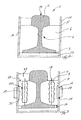
- drawing figure 1 is a plan view of an embedded rail 1, which has a rail head 2, a rail foot 3 and at least one rail chamber 4 and is mounted on an insulating mat (see. FIGS. 2 and 3 ).
- the rail 1 is at least partially surrounded by a Kammer hypollelement 6 and arranged with this in an embedding channel 5.
- the rail 1 is fixed by holding sections 7 at least in the groove 5, wherein the actual fixation only by the introduction of spreading elements 8 in the holding sections 7 between the rail chamber 4 and the inner wall 9 of the embedding trough 5 takes place.
- the Kammer spalletti 6 and the holding sections 7 alternate along the longitudinal direction of the rail 1, while the Kammer hypoll comprise 6 are formed longer than the holding portions 7.
- the advantage of this is that the Kammer hypollemia 6 are easier to manufacture and thus the Total costs for the embedding of the rail 1 can be reduced.
- only the holding sections 7 are spread with the expansion element 8, the Kammer hypollide 6 are not braced and surround the rail 1 in the embedding trough 5 only.
- the U-shaped cross section of the embedding trough 5 is clearly visible.
- the lateral legs 10, 11 of the U-shaped embedding trough 5 extend in the final assembly state to below the highest point 12 of the rail head 2.
- the holding sections 7 provided with the spreading elements 8 are arranged in pairs on both sides of the rail 1 opposite one another. If necessary, the holding sections can also be mounted with offset in the rail longitudinal direction.
- the embedding channel 5 is provided on at least one of its inwardly facing walls 10, 11 at least with an engagement element 15 which engages with an anchor element 16 contacting the corresponding retaining section 7 (cf. Fig. 3 ).
- the engagement element 15 can also be in engagement with a corresponding counter element (not shown) of the holding section 7.
- the engagement member 15 is formed as an opening 17 and forms with the anchor member 16 is a positive connection.
- the expansion element 8 is accommodated in a Spreizelementaus simplifiedung 18 of the holding portion 7, wherein only by the removal of the expansion element 8 from the Spreizelementausnaturalung 18 by deforming or pivoting the partition wall 19 it is possible to lift the positive engagement of anchor element 16 and the holding portion 7 and finally the entire Fixation of the rail 1 to solve.
- the expansion element 8 closes in the final assembly state flush with the upper edge 20 of the holding section 7 and can be coated with a potting compound 35 at least on a rail side (through which no rail vehicle moves), which provides mechanical protection against dirt .
- the expander 8 in its cross-sectional contour undercuts 21, for example, form a drop or diamond-shaped shape of the expansion element 8.
- the spreading element 8 shown in drawing Figure 3 has a sawtooth-like cross-sectional contour, wherein the perpendicular of the bevels partly to the bottom region of the embedding trough 5 have.
- the expansion element 8 is plate-shaped and corresponds in length approximately to the length of the holding portion 7.
- the expansion element 8 For better disassembly of the expansion element 8 from the Spreizelementaus Principleung 18, it is provided to provide engaging recesses in the region of its top 22 or end face 23, in which a tool can engage and thereby facilitate disassembly.
- the engagement recess is formed as a bore provided with an internal thread, which is protected with a cover element from dirt or other environmental residues.
- the anchor member 16 protrudes through the opening 17 of the embedding channel 5 and anchored in the final assembly position outside of the embedding channel 5.
- both the holding section 7 which is in contact with the anchor element 16, the rail 1 arranged thereon and the embedding channel 5 are connected to the surrounding building material, e.g. Concrete is fixed relative to each other.
- the anchor element 16 does not necessarily have to protrude through the opening 17, alternatively it is also conceivable that the anchor element 16 engages in a recess of the embedding channel 5 and the embedding channel 5 in turn via a Emphasis and / or a recess with the embedding channel 5 surrounding building material forms a positive connection (not shown).
- the anchor element 16 has at least two different cross-sectional areas 24, 25.
- a cross-sectional area 24, 25 is preferably configured in such a way that the anchor element 16 is connected in a manner secure against rotation with the recess, opening 17 or emphasis of the embedding channel 5.
- At least one end region, for example cross-sectional area 25 of the anchor element 16 is received in an anchor recess 26 of the holding section 7 corresponding at least in regions.
- the anchor recess 26 is formed in the manner of a longitudinal groove and prevented by its shape twisting of the anchor member 16.
- the anchor member 16 is longitudinally displaceably received in the anchor recess 26 so that the provided with the Ankerausströmung 26 holding portions 7 can be easily mounted .
- this rests with its lower edge 27 or surface on the anchor recess 26 of the stationary holding portion 7 and with its upper edge 28 or surface a defined distance 29 to the upper portion 30 of the anchor recess 26 ( see drawing figure 5).
- the anchor recess 26 also extends equidistant and parallel to the rail longitudinal axis. 9
- the assembly and disassembly of the system is further facilitated by the SpreizelementausEnglishung 18 is at least partially disposed in the vicinity of the anchor recess 26 and the depth 31 of the Spreizelementausnaturalung 18 extends at least to half of the opening 17 to the lower half of the anchor recess 26.
- the lower end of the Spreizelementaus aloneung 18 is lower than the lower edge 32 of the anchor recess 26th
- the cross-sectional contour of the Spreizelementausnaturalung 18 is essentially the Cross-sectional contour of the expansion element 8 adapted.
- the Spreizelementausnaturalung 18 is mirror-symmetrical and designed in the manner of a longitudinal groove.
- the holding sections 7 are advantageously provided with sliding inclined surfaces (not shown), which are arranged, for example, on the surface 33 facing the embedding channel 5.
- sliding inclined surfaces not shown
- the embedding trough 5 preferably in its lower region a plurality of water drainage openings (not shown) and these water drainage openings channels or channels of Kammerhellemias 6, holding section 7 of the insulating mat 13 and / or the Sp Sonettis 8 lead to the rainwater targeted on the water drainage openings to lead the embedding trough 5.
Landscapes
- Engineering & Computer Science (AREA)
- Architecture (AREA)
- Civil Engineering (AREA)
- Structural Engineering (AREA)
- Connection Of Plates (AREA)
Applications Claiming Priority (1)
| Application Number | Priority Date | Filing Date | Title |
|---|---|---|---|
| DE200710027574 DE102007027574B3 (de) | 2007-06-12 | 2007-06-12 | Eingebettete Schiene für Schienenfahrzeuge sowie Verfahren zur Montage derselben |
Publications (1)
| Publication Number | Publication Date |
|---|---|
| EP2003246A1 true EP2003246A1 (fr) | 2008-12-17 |
Family
ID=39713939
Family Applications (1)
| Application Number | Title | Priority Date | Filing Date |
|---|---|---|---|
| EP08010678A Withdrawn EP2003246A1 (fr) | 2007-06-12 | 2008-06-12 | Rails encastrés pour véhicules sur rails et leur procédé de montage |
Country Status (2)
| Country | Link |
|---|---|
| EP (1) | EP2003246A1 (fr) |
| DE (1) | DE102007027574B3 (fr) |
Families Citing this family (1)
| Publication number | Priority date | Publication date | Assignee | Title |
|---|---|---|---|---|
| CN115404729B (zh) * | 2022-08-25 | 2024-09-24 | 海宁由拳铁路器材有限公司 | 一种铁路预埋铁座的更换工艺 |
Citations (7)
| Publication number | Priority date | Publication date | Assignee | Title |
|---|---|---|---|---|
| DE608849C (de) | 1931-10-09 | 1935-02-01 | Jakob Dietrich | Selbstspannende Schienenbefestigung |
| DE8711451U1 (de) * | 1987-08-24 | 1988-12-22 | Phoenix Ag, 2100 Hamburg | Elastisches Stützlager für Rillen- oder Blockschienen |
| DE19519745A1 (de) * | 1995-05-30 | 1997-01-16 | Clouth Gummiwerke Ag | Schotterloser Gleisoberbau |
| DE19628529A1 (de) * | 1996-07-02 | 1998-01-08 | Etw Weichenbau Zossen Gmbh I K | Erschütterungsarmes Gleis |
| US5788153A (en) | 1994-08-02 | 1998-08-04 | Ortwein; Hermann | Infrastructure for railway tracks |
| EP0937817A1 (fr) * | 1998-02-19 | 1999-08-25 | DVG Deutsche Verpackungsmittel-GmbH | Elément de remplissage pour rails, notamment des rails de tramway |
| WO2003012203A2 (fr) | 2001-08-02 | 2003-02-13 | Balfour Beatty Plc | Ensemble rail |
Family Cites Families (1)
| Publication number | Priority date | Publication date | Assignee | Title |
|---|---|---|---|---|
| DE10001605C1 (de) * | 2000-01-17 | 2001-09-27 | Sedra Asphalt Technik Biebrich | Kammerfüllelement mit Umkleidung |
-
2007
- 2007-06-12 DE DE200710027574 patent/DE102007027574B3/de not_active Expired - Fee Related
-
2008
- 2008-06-12 EP EP08010678A patent/EP2003246A1/fr not_active Withdrawn
Patent Citations (7)
| Publication number | Priority date | Publication date | Assignee | Title |
|---|---|---|---|---|
| DE608849C (de) | 1931-10-09 | 1935-02-01 | Jakob Dietrich | Selbstspannende Schienenbefestigung |
| DE8711451U1 (de) * | 1987-08-24 | 1988-12-22 | Phoenix Ag, 2100 Hamburg | Elastisches Stützlager für Rillen- oder Blockschienen |
| US5788153A (en) | 1994-08-02 | 1998-08-04 | Ortwein; Hermann | Infrastructure for railway tracks |
| DE19519745A1 (de) * | 1995-05-30 | 1997-01-16 | Clouth Gummiwerke Ag | Schotterloser Gleisoberbau |
| DE19628529A1 (de) * | 1996-07-02 | 1998-01-08 | Etw Weichenbau Zossen Gmbh I K | Erschütterungsarmes Gleis |
| EP0937817A1 (fr) * | 1998-02-19 | 1999-08-25 | DVG Deutsche Verpackungsmittel-GmbH | Elément de remplissage pour rails, notamment des rails de tramway |
| WO2003012203A2 (fr) | 2001-08-02 | 2003-02-13 | Balfour Beatty Plc | Ensemble rail |
Also Published As
| Publication number | Publication date |
|---|---|
| DE102007027574B3 (de) | 2009-02-26 |
Similar Documents
| Publication | Publication Date | Title |
|---|---|---|
| EP3081706B1 (fr) | Rails d'ancrage dans le béton | |
| EP3437954B1 (fr) | Dispositif de protection | |
| EP2987595B1 (fr) | Agencement destiné à la fabrication de préfabriqués en béton doté d'au moins un rail d'ancrage intégré dans le préfabriqué en béton et procédé de fabrication de tels préfabriqués en béton | |
| WO2013079210A2 (fr) | Dispositif de fixation à cheville et armature | |
| DE102012107732A1 (de) | Kunststoffdübel für die Befestigung einer Schiene und Kombination aus einem solchen Kunststoffdübel und einer Schwellenschraube | |
| WO2015028680A1 (fr) | Insert d'assemblage ainsi que procédé d'inclusion et procédé de fabrication correspondant | |
| EP2322719A2 (fr) | Dispositifs destinés à enjamber des joints de dilatation, construction de profilé et procédé de fabrication de profilés de joints | |
| EP2817457A1 (fr) | Dispositif anti-bruit | |
| EP2543548B1 (fr) | Système de fixation pour un support de toit de véhicule | |
| DE8916127U1 (de) | Vorrichtung zur federnden Einspannung von Traversen einer Fahrbahnüberbrückungskonstruktion | |
| EP3485089B1 (fr) | Système d'amortissement pour voies | |
| EP3990715B1 (fr) | Élément d'ancrage et procédé de montage d'un rail d'ancrage dans un élément de construction en béton | |
| DE102007027574B3 (de) | Eingebettete Schiene für Schienenfahrzeuge sowie Verfahren zur Montage derselben | |
| EP1124014A2 (fr) | Element de paroi en béton pour barrière de sécurité routière | |
| EP0952252B1 (fr) | Coffrage pour l'encastrement d'un rail | |
| EP2363529B1 (fr) | Système de fixation d'un rail | |
| EP1789629A1 (fr) | Dispositif pour guider un rail sur une traverse en beton | |
| EP3617404B1 (fr) | Rail de roulement et structure de voie dotée du rail de roulement | |
| EP2520719B1 (fr) | Système de retenue de véhicule doté de tapis de collision | |
| DE102004045766B4 (de) | Fertigteilplatte und Verfahren zur Herstellung einer festen Fahrbahn mit einer derartigen Fertigteilplatte | |
| EP3420133B1 (fr) | Système de fixation de rail | |
| WO2011144394A2 (fr) | Rail de montage | |
| DE102011105334B4 (de) | Schacht aus Beton und Lastaufnahmeelement | |
| EP2000726A2 (fr) | Abattoir en béton | |
| EP1830002B1 (fr) | Système de support de rails pour voie ferrée |
Legal Events
| Date | Code | Title | Description |
|---|---|---|---|
| PUAI | Public reference made under article 153(3) epc to a published international application that has entered the european phase |
Free format text: ORIGINAL CODE: 0009012 |
|
| AK | Designated contracting states |
Kind code of ref document: A1 Designated state(s): AT BE BG CH CY CZ DE DK EE ES FI FR GB GR HR HU IE IS IT LI LT LU LV MC MT NL NO PL PT RO SE SI SK TR |
|
| AX | Request for extension of the european patent |
Extension state: AL BA MK RS |
|
| 17P | Request for examination filed |
Effective date: 20090616 |
|
| AKX | Designation fees paid |
Designated state(s): AT BE BG CH CY CZ DE DK EE ES FI FR GB GR HR HU IE IS IT LI LT LU LV MC MT NL NO PL PT RO SE SI SK TR |
|
| GRAP | Despatch of communication of intention to grant a patent |
Free format text: ORIGINAL CODE: EPIDOSNIGR1 |
|
| STAA | Information on the status of an ep patent application or granted ep patent |
Free format text: STATUS: THE APPLICATION IS DEEMED TO BE WITHDRAWN |
|
| 18D | Application deemed to be withdrawn |
Effective date: 20120103 |