EP2003292A2 - Bande de recouvrement d'aube dotée d'un rebord - Google Patents
Bande de recouvrement d'aube dotée d'un rebord Download PDFInfo
- Publication number
- EP2003292A2 EP2003292A2 EP08010395A EP08010395A EP2003292A2 EP 2003292 A2 EP2003292 A2 EP 2003292A2 EP 08010395 A EP08010395 A EP 08010395A EP 08010395 A EP08010395 A EP 08010395A EP 2003292 A2 EP2003292 A2 EP 2003292A2
- Authority
- EP
- European Patent Office
- Prior art keywords
- shroud
- edge
- blade
- flow path
- main flow
- Prior art date
- Legal status (The legal status is an assumption and is not a legal conclusion. Google has not performed a legal analysis and makes no representation as to the accuracy of the status listed.)
- Granted
Links
Images


Classifications
-
- F—MECHANICAL ENGINEERING; LIGHTING; HEATING; WEAPONS; BLASTING
- F01—MACHINES OR ENGINES IN GENERAL; ENGINE PLANTS IN GENERAL; STEAM ENGINES
- F01D—NON-POSITIVE DISPLACEMENT MACHINES OR ENGINES, e.g. STEAM TURBINES
- F01D5/00—Blades; Blade-carrying members; Heating, heat-insulating, cooling or antivibration means on the blades or the members
- F01D5/12—Blades
- F01D5/22—Blade-to-blade connections, e.g. for damping vibrations
- F01D5/225—Blade-to-blade connections, e.g. for damping vibrations by shrouding
-
- F—MECHANICAL ENGINEERING; LIGHTING; HEATING; WEAPONS; BLASTING
- F01—MACHINES OR ENGINES IN GENERAL; ENGINE PLANTS IN GENERAL; STEAM ENGINES
- F01D—NON-POSITIVE DISPLACEMENT MACHINES OR ENGINES, e.g. STEAM TURBINES
- F01D11/00—Preventing or minimising internal leakage of working-fluid, e.g. between stages
- F01D11/001—Preventing or minimising internal leakage of working-fluid, e.g. between stages for sealing space between stator blade and rotor
-
- F—MECHANICAL ENGINEERING; LIGHTING; HEATING; WEAPONS; BLASTING
- F01—MACHINES OR ENGINES IN GENERAL; ENGINE PLANTS IN GENERAL; STEAM ENGINES
- F01D—NON-POSITIVE DISPLACEMENT MACHINES OR ENGINES, e.g. STEAM TURBINES
- F01D11/00—Preventing or minimising internal leakage of working-fluid, e.g. between stages
- F01D11/08—Preventing or minimising internal leakage of working-fluid, e.g. between stages for sealing space between rotor blade tips and stator
-
- F—MECHANICAL ENGINEERING; LIGHTING; HEATING; WEAPONS; BLASTING
- F01—MACHINES OR ENGINES IN GENERAL; ENGINE PLANTS IN GENERAL; STEAM ENGINES
- F01D—NON-POSITIVE DISPLACEMENT MACHINES OR ENGINES, e.g. STEAM TURBINES
- F01D17/00—Regulating or controlling by varying flow
- F01D17/10—Final actuators
- F01D17/12—Final actuators arranged in stator parts
- F01D17/14—Final actuators arranged in stator parts varying effective cross-sectional area of nozzles or guide conduits
- F01D17/16—Final actuators arranged in stator parts varying effective cross-sectional area of nozzles or guide conduits by means of nozzle vanes
- F01D17/162—Final actuators arranged in stator parts varying effective cross-sectional area of nozzles or guide conduits by means of nozzle vanes for axial flow, i.e. the vanes turning around axes which are essentially perpendicular to the rotor centre line
-
- F—MECHANICAL ENGINEERING; LIGHTING; HEATING; WEAPONS; BLASTING
- F01—MACHINES OR ENGINES IN GENERAL; ENGINE PLANTS IN GENERAL; STEAM ENGINES
- F01D—NON-POSITIVE DISPLACEMENT MACHINES OR ENGINES, e.g. STEAM TURBINES
- F01D5/00—Blades; Blade-carrying members; Heating, heat-insulating, cooling or antivibration means on the blades or the members
- F01D5/12—Blades
- F01D5/14—Form or construction
- F01D5/141—Shape, i.e. outer, aerodynamic form
- F01D5/142—Shape, i.e. outer, aerodynamic form of the blades of successive rotor or stator blade-rows
- F01D5/143—Contour of the outer or inner working fluid flow path wall, i.e. shroud or hub contour
-
- F—MECHANICAL ENGINEERING; LIGHTING; HEATING; WEAPONS; BLASTING
- F04—POSITIVE - DISPLACEMENT MACHINES FOR LIQUIDS; PUMPS FOR LIQUIDS OR ELASTIC FLUIDS
- F04D—NON-POSITIVE-DISPLACEMENT PUMPS
- F04D29/00—Details, component parts, or accessories
- F04D29/66—Combating cavitation, whirls, noise, vibration or the like; Balancing
- F04D29/68—Combating cavitation, whirls, noise, vibration or the like; Balancing by influencing boundary layers
- F04D29/681—Combating cavitation, whirls, noise, vibration or the like; Balancing by influencing boundary layers especially adapted for elastic fluid pumps
- F04D29/685—Inducing localised fluid recirculation in the stator-rotor interface
-
- F—MECHANICAL ENGINEERING; LIGHTING; HEATING; WEAPONS; BLASTING
- F05—INDEXING SCHEMES RELATING TO ENGINES OR PUMPS IN VARIOUS SUBCLASSES OF CLASSES F01-F04
- F05B—INDEXING SCHEME RELATING TO WIND, SPRING, WEIGHT, INERTIA OR LIKE MOTORS, TO MACHINES OR ENGINES FOR LIQUIDS COVERED BY SUBCLASSES F03B, F03D AND F03G
- F05B2240/00—Components
- F05B2240/20—Rotors
- F05B2240/33—Shrouds which are part of or which are rotating with the rotor
-
- Y—GENERAL TAGGING OF NEW TECHNOLOGICAL DEVELOPMENTS; GENERAL TAGGING OF CROSS-SECTIONAL TECHNOLOGIES SPANNING OVER SEVERAL SECTIONS OF THE IPC; TECHNICAL SUBJECTS COVERED BY FORMER USPC CROSS-REFERENCE ART COLLECTIONS [XRACs] AND DIGESTS
- Y02—TECHNOLOGIES OR APPLICATIONS FOR MITIGATION OR ADAPTATION AGAINST CLIMATE CHANGE
- Y02T—CLIMATE CHANGE MITIGATION TECHNOLOGIES RELATED TO TRANSPORTATION
- Y02T50/00—Aeronautics or air transport
- Y02T50/60—Efficient propulsion technologies, e.g. for aircraft
Definitions
- the present invention relates to blade rows of fluid flow machines such as fans, compressors, pumps and fans of axial or semi-axial design with gaseous or liquid working fluid.
- the turbomachine may include one or more stages, each having a rotor and a stator, in some cases the stage is merely formed by a rotor.
- the rotor consists of a number of blades, which are connected to the rotating shaft of the machine and deliver energy to the working fluid.
- the rotor can be designed with or without shroud on the outer blade end.
- the stator consists of a number of stationary blades, which can be designed on the hub side as the housing side with a fixed or free blade end.
- the rotor drum and the blading are usually surrounded by a housing.
- the machine may also have a stator in front of the first rotor, a so-called leading wheel. At least one stator or Vorleitrad - may be rotatably mounted - deviating from the immovable fixation - to change the angle of attack. An adjustment is made for example by a spindle accessible from outside the annular channel.
- said multi-stage turbomachine may have two counterrotating shafts so that the rotor blade rows change direction of rotation from stage to stage. There are no stators between successive rotors.
- the fluid flow machine can alternatively have a bypass configuration such that the single-flow annular channel divides behind a certain row of blades into two concentric annular channels, which in turn accommodate at least one additional row of blades.
- Fig. 2 shows by way of example four possible configurations of the fluid flow machine.
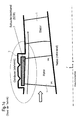
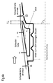
- the 1a schematically shows a portion of a fluid flow machine, consisting of a rotor blade row and a stator blade row. Particularly emphasized is the shroud arrangement at the outer blade end of the rotor. According to the prior art, the shroud arrangement consists of a large cavity, which is provided in the housing and completely absorbs the shroud to create a smooth as possible outer main flow path boundary.
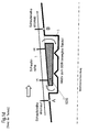
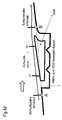
- the 1b shows schematically shows a portion of a fluid flow machine, consisting of a fixed stator blade row and a rotor blade row. Particularly emphasized is the shroud arrangement at the inner blade end of the fixed stator. According to the prior art, the shroud arrangement from a large cavity provided in the hub, which completely accommodates the shroud to provide the smoothest possible internal main flow path boundary.
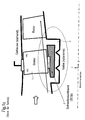
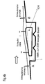
- the Figure 1C schematically shows a portion of a fluid flow machine, consisting of a series of adjustable (variable) stators and a rotor blade row. Particularly emphasized is the shroud arrangement on the inner blade end of the adjusting stator. According to the prior art, the shroud arrangement here also consists of a large cavity, which is provided in the hub and which completely absorbs the shroud in order to create the smoothest possible inner main flow path boundary.
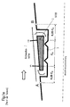
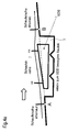
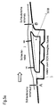
- the Fig.1d shows, representative of shrouds of adjustable or fixed rotors and stators, an arrangement of three rows of blades at the edge of the main flow path of a fluid flow machine, consisting of an upstream row of blades, a row of blades with shroud and a downstream row of blades.
- This representation may be both a region on the housing and a region on the hub of the fluid flow machine.
- the shroud is embedded in a surrounding component or a surrounding assembly (rotor hub or housing) and fits smoothly in the course of the main flow path according to the prior art without any projection.
- the shroud may be solid or (not shown here) hollow and consists of one or more components.
- the leakage flow occurring between the shroud and the surrounding component (small arrows), which runs counter to the main flow direction (thick arrow), is reduced by a number of sealing tips.
- the sealing tips can be arranged on the surrounding component or also (as not shown here) on the shroud itself be. There is usually a relative movement between the surrounding component and the shroud. In the area of the shroud, the leading edge (VK) and trailing edge (HK) of the considered blade row are indicated.
- the trailing edge of the upstream blade row is indicated; the base of this HK is marked with A.
- the leading edge of the upstream blade row is indicated; the base of this VK is marked B.
- a thin long arrow characterizes the near-edge flow along the substantially smooth boundary of the main flow path. According to the prior art, the shroud does not protrude beyond the connecting line between A and B in the main flow path. A very slight supernatant, but measured against other dimensions of the shroud subordinate small, can occur in the prior art due to manufacturing tolerances or come to operating points of the fluid flow machine off the design state by thermal detuning of the components.
- Fig.1d sketched enters the flow in the edge region of the main flow path without influencing by a paragraph or unevenness in the contour in the blade row with shroud and runs smoothly over the arranged in alignment with the rest of the contour shroud away.
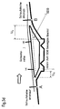
- the position of the point A is determined by a distance from the leading edge of 25% of the axial length Cx at the edge of the shrouded blade row, see 1E ,
- the position of point B is determined by a distance to the trailing edge of 25% of the axial length Cx at the edge of the shrouded blade row, see 1E ,
- the invention has for its object to provide a fluid flow machine of the type mentioned, which avoids the disadvantages of the prior art and minimizes shroud leakage flows.
- the present invention includes designing a shroud of the blade row of a fluid power machine such that at least one location of the perimeter and at least one of the leading and trailing areas, the contour of the shroud extends beyond a straight line of the adjacent blade edges of adjacent blade rows such that in the region of one of the openings, with which the shroud cavity communicates with the main flow path, there is a curved course of the main flow path contour and the flow lines at the edge of the main flow path.
- a bucket cover assembly for use in a turbomachine, which is provided by a local projection in the region of the leading edge and / or the trailing edge additionally influences the course of the flow at the edge of the main flow path and in this way reduces the pressure gradient acting on the cavity for the shroud leakage flow.
- a conventional prior art shroud configuration as shown in FIG Fig.1d is shown, provides an entry of the edge flow in the blade row with shroud before influenced by a paragraph or unevenness in the contour.
- the flow passes smoothly over the openings of the shroud cavity, the side facing the main flow path and arranged in alignment with the upstream and downstream contour side of the shroud away.
- the applied to the Kavticiansötechnisch static pressures that determine the leakage current are fixed in such an arrangement.
- Purpose of the present inventive solution is to influence the static pressure at the leading edge and the trailing edge of the shroud by special shape of the shroud in the area of the Schaufelvorder- and / or the blade trailing edge so that the static pressure gradient between the Openings of the cavity and thus the leakage current is reduced or ideally prevented.
- Inventive shroud configurations are in Fig.3a to Fig.5d shown.
- Decisive for the present invention is solely the contour shaping of the shroud in the vicinity of the main flow path.
- the subject of the invention is the shape of the shroud in the deeper interior of the cavity in which the shroud is embedded.
- the subject of the invention is the exact design of the components surrounding the cavity and the design of the sealing tips.
- the aforementioned non-inventive features are outlined here for the sake of clarity only in so far simplified form, as is necessary for the representation and understanding of relevant relationships of the invention.
- FIG.3c show by way of example some shroud configurations according to the invention with a projection in the region of the front edge of the relevant blade row.
- a supernatant according to the invention is characterized in that in at least one freely selectable longitudinal section of the turbomachine, a portion of the shroud protrudes beyond the connecting line AB into the main flow path and in this way represents a perceptible resistance to the approaching flow.
- FIG. 3a shows a solution according to the invention, in which the projecting leading edge of the shroud is provided for better flow guidance with a rounding that can end upstream or downstream of the blade leading edge.
- 3b shows a solution according to the invention, in which the protruding leading edge of the shroud is provided for stagnation and better flow guidance with a nose whose Rounding on the main flow path side facing upstream or may end downstream of the blade leading edge.
- 3 c shows a solution according to the invention, in which the protruding leading edge of the shroud is provided for stagnation and better flow guidance with an overlap Ux.
- the overlap is characterized in that the upstream direction limiting wall of the cavity is not completely radially and rectilinearly, but at least locally obliquely upstream oriented so that a likewise oblique design of the shroud on the mainstream side facing away from the formation of a tilted against the radial direction and optionally curved channel between the shroud and the surrounding component results.
- the 4a to 4e show by way of example some shroud configurations according to the invention with a projection in the region of the trailing edge of the relevant blade row.
- a supernatant according to the invention is characterized in that in at least one freely selectable longitudinal section of the turbomachine, a portion of the shroud protrudes beyond the connecting line AB into the main flow path and in this way represents a return of the flow-limiting contour.
- FIG. 4a shows a solution according to the invention, in which the trailing edge of the shroud is designed substantially truncated.
- FIG. 4b shows a solution according to the invention, in which the trailing edge of the shroud is provided for better flow guidance with a rounding that can end downstream or upstream of the blade trailing edge.
- FIG. 4c shows a solution according to the invention, in which the trailing edge of the shroud is designed substantially sharp-edged.
- Fig.4d shows a solution according to the invention, in which the trailing edge of the shroud is provided for better flow guidance with a nose whose rounding can end on the main flow path side facing downstream or upstream of the blade trailing edge.
- FIG.4E shows a solution according to the invention, in which the trailing edge of the shroud is provided with an overlap Ux.
- the overlap is characterized in that the downstream end wall of the cavity is not completely radially and rectilinearly, but at least locally obliquely oriented downstream, so that a likewise oblique design of the shroud on the mainstream side facing away from the formation of a tilted against the radial direction and optionally curved channel between the shroud and the surrounding component results.
- Fig.5a to Fig.5d show by way of example some shroud configurations according to the invention with a projection in the region of the leading edge and in the region of the trailing edge of the relevant blade row.
- An inventive supernatant is characterized in that in at least one freely selectable longitudinal section of the fluid flow machine is a proportion of the shroud over the connecting line AB also in the main flow path.
- FIG. 5a shows a solution according to the invention, in which the projecting leading edge of the shroud is provided for better flow guidance with a rounding, wherein the trailing edge of the shroud is designed nose-shaped, and in which the Main flow path facing contour of the shroud within the blade row is substantially rectilinear.
- 5 b shows a solution according to the invention, in which the main flow path-facing contour of the shroud within the blade row is substantially concave.
- 5c shows a solution according to the invention, in which the main flow path-facing contour of the shroud within the blade row is substantially convex.
- 5d shows a solution according to the invention, in which the projecting leading edge of the shroud and also the projecting trailing edge of the shroud are designed for better flow guidance with overlap, and in which the main flow path-facing contour of the shroud within the blade row is substantially rectilinear.
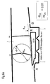
- the 6a shows a configuration with shroud overhang in the leading edge area.
- a tangent parallel to the connecting line AB at the position of maximum shroud protrusion defines the size of the shroud protrusion.
- the size of the maximum projection dVK is defined according to the invention relative to the annular channel width WVK at the front edge.
- the ring channel width WVK results as the diameter of a circle inscribed in the ring channel (main flow path) with the center MVK on the leading edge. According to the invention: dVK / WVK> 0.01.
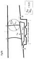
- the Figure 6b shows a configuration with shroud overhang in the trailing edge region.
- One parallel to the connecting line AB extending tangent to the location of maximum shroud protrusion defines the size of the shroud protrusion.
- the size of the maximum projection dHK is defined according to the invention relative to the annular channel width WHK at the trailing edge.
- the annular channel width WHK results as the diameter of a circle inscribed in the annular channel (main flow path) with the center MIC on the trailing edge. According to the invention: dHK / WHK> 0.01.
- the shroud protrusion in the leading edge region dVK is determined directly at the leading edge and the shroud projection in the trailing edge region dHK directly at the trailing edge.
- the Figure 7 defines favorable Axialerstreckened the shroud of the invention with supernatant. Due to the pressure field that arises due to the shroud overhang in the region of the shroud edges, it is particularly favorable to provide a comparatively long free section XVK of the shroud upstream of the blade leading edge. How out Fig. 7 it can be seen, this invention should be at least 7% of the axial extent of the blade row at the edge of the main flow path.
- this invention should be at least 7% of the axial extent of the blade row at the edge of the main flow path.
- the Figure 8 shows in a spatial view the leading edge region of a blade row with shroud over a portion of the circumference.
- the representation in FIG Figure 8 shows the inventive concept using the example of the leading edge region of a blade row with shroud, but the invention applies here also applies to a shroud overhang in the trailing edge region.
- the present invention allows a significantly higher aerodynamic load capacity of rotors and stators in turbomachines, with constant or increased efficiency.
- a reduction in specific fuel consumption of up to 0.5% is to be expected.
Landscapes
- Engineering & Computer Science (AREA)
- Mechanical Engineering (AREA)
- General Engineering & Computer Science (AREA)
- Physics & Mathematics (AREA)
- Fluid Mechanics (AREA)
- Structures Of Non-Positive Displacement Pumps (AREA)
Applications Claiming Priority (1)
| Application Number | Priority Date | Filing Date | Title |
|---|---|---|---|
| DE102007027427A DE102007027427A1 (de) | 2007-06-14 | 2007-06-14 | Schaufeldeckband mit Überstand |
Publications (3)
| Publication Number | Publication Date |
|---|---|
| EP2003292A2 true EP2003292A2 (fr) | 2008-12-17 |
| EP2003292A3 EP2003292A3 (fr) | 2012-04-04 |
| EP2003292B1 EP2003292B1 (fr) | 2019-12-18 |
Family
ID=39739925
Family Applications (1)
| Application Number | Title | Priority Date | Filing Date |
|---|---|---|---|
| EP08010395.5A Ceased EP2003292B1 (fr) | 2007-06-14 | 2008-06-06 | Machine de travail fluidique avec virole d'aube dotée d'un rebord |
Country Status (3)
| Country | Link |
|---|---|
| US (1) | US8202044B2 (fr) |
| EP (1) | EP2003292B1 (fr) |
| DE (1) | DE102007027427A1 (fr) |
Cited By (4)
| Publication number | Priority date | Publication date | Assignee | Title |
|---|---|---|---|---|
| EP2607625A1 (fr) * | 2011-12-20 | 2013-06-26 | MTU Aero Engines GmbH | Turbomachine et étage de turbomachine |
| KR20130131452A (ko) * | 2011-03-30 | 2013-12-03 | 미츠비시 쥬고교 가부시키가이샤 | 가스 터빈 및 외측 슈라우드 |
| EP2806103A1 (fr) * | 2013-05-24 | 2014-11-26 | MTU Aero Engines GmbH | Grille d'aubes, aubes et turbomachine |
| EP2617942A4 (fr) * | 2010-09-17 | 2018-02-28 | Mitsubishi Hitachi Power Systems, Ltd. | Turbine |
Families Citing this family (15)
| Publication number | Priority date | Publication date | Assignee | Title |
|---|---|---|---|---|
| GB0901473D0 (en) * | 2009-01-30 | 2009-03-11 | Rolls Royce Plc | An axial-flow turbo machine |
| EP2462412A4 (fr) * | 2009-08-06 | 2014-01-22 | Airbus Engineering Ct India | Système et procédé de calcul d'un point d'équidistance (edp) pour aéronefs |
| US8714908B2 (en) * | 2010-11-05 | 2014-05-06 | General Electric Company | Shroud leakage cover |
| JP2012233406A (ja) * | 2011-04-28 | 2012-11-29 | Hitachi Ltd | ガスタービン静翼 |
| US9885368B2 (en) | 2012-05-24 | 2018-02-06 | Carrier Corporation | Stall margin enhancement of axial fan with rotating shroud |
| US20140140822A1 (en) * | 2012-11-16 | 2014-05-22 | General Electric Company | Contoured Stator Shroud |
| US20160305264A1 (en) * | 2013-12-05 | 2016-10-20 | United Technologies Corporation | Turbomachine rotor-stator seal |
| US9938840B2 (en) * | 2015-02-10 | 2018-04-10 | United Technologies Corporation | Stator vane with platform having sloped face |
| US10161250B2 (en) * | 2015-02-10 | 2018-12-25 | United Technologies Corporation | Rotor with axial arm having protruding ramp |
| DE102015206384A1 (de) * | 2015-04-09 | 2016-10-13 | Rolls-Royce Deutschland Ltd & Co Kg | Deckbandanordnung einer Schaufelreihe von Stator- oder Rotorschaufeln |
| BE1025961B1 (fr) * | 2018-01-30 | 2019-08-28 | Safran Aero Boosters S.A. | Passage annulaire entre une virole et une plateforme rotorique de turbomachine |
| JP7325213B2 (ja) * | 2019-04-10 | 2023-08-14 | 三菱重工業株式会社 | 静翼ユニットおよび圧縮機並びにガスタービン |
| FR3106626B1 (fr) * | 2020-01-24 | 2022-06-10 | Safran Aircraft Engines | Basculement differencié entre rotor et stator aux entrefers rotor-stator dans un compresseur de turbomachine |
| FR3106627B1 (fr) | 2020-01-24 | 2023-03-17 | Safran Aircraft Engines | Basculement en vagues aux entrefers rotor-stator dans un compresseur de turbomachine |
| WO2026074111A1 (fr) * | 2024-10-03 | 2026-04-09 | Safran Aero Boosters | Turbomachine d'aéronef |
Family Cites Families (17)
| Publication number | Priority date | Publication date | Assignee | Title |
|---|---|---|---|---|
| CH112269A (de) * | 1923-12-22 | 1925-10-16 | Erste Bruenner Maschinen Fab | Schaufeleinrichtung an axialen Dampf- oder Gasturbinen. |
| US3065955A (en) * | 1958-12-29 | 1962-11-27 | Gen Electric | Rotor blade and shroud assembly |
| CH432554A (de) * | 1965-04-22 | 1967-03-31 | Escher Wyss Ag | Gleichdruck-Turbinenstufe |
| US3640638A (en) * | 1969-07-02 | 1972-02-08 | Rolls Royce | Axial flow compressor |
| JPS5447907A (en) * | 1977-09-26 | 1979-04-16 | Hitachi Ltd | Blading structure for axial-flow fluid machine |
| US4844692A (en) * | 1988-08-12 | 1989-07-04 | Avco Corporation | Contoured step entry rotor casing |
| FR2666846B1 (fr) * | 1990-09-13 | 1992-10-16 | Alsthom Gec | Grille d'aubes pour turbomachine munie de fentes d'aspiration dans le plafond et/ou dans le plancher et turbomachine comportant ces grilles. |
| DE69305326T2 (de) * | 1992-02-10 | 1997-05-07 | United Technologies Corp | Ejektor für kühlfluid |
| US5488825A (en) * | 1994-10-31 | 1996-02-06 | Westinghouse Electric Corporation | Gas turbine vane with enhanced cooling |
| US5607284A (en) * | 1994-12-29 | 1997-03-04 | United Technologies Corporation | Baffled passage casing treatment for compressor blades |
| DE59609405D1 (de) * | 1996-04-01 | 2002-08-08 | Alstom | Wandkontur für eine axiale Strömungsmaschine |
| JPH10184304A (ja) * | 1996-12-27 | 1998-07-14 | Toshiba Corp | 軸流タービンのタービンノズルおよびタービン動翼 |
| JP3883245B2 (ja) * | 1997-02-26 | 2007-02-21 | 株式会社東芝 | 軸流タービン |
| US6511294B1 (en) * | 1999-09-23 | 2003-01-28 | General Electric Company | Reduced-stress compressor blisk flowpath |
| JP2002371802A (ja) * | 2001-06-14 | 2002-12-26 | Mitsubishi Heavy Ind Ltd | ガスタービンにおけるシュラウド一体型動翼と分割環 |
| US7063509B2 (en) * | 2003-09-05 | 2006-06-20 | General Electric Company | Conical tip shroud fillet for a turbine bucket |
| JP2006138259A (ja) * | 2004-11-12 | 2006-06-01 | Mitsubishi Heavy Ind Ltd | 軸流タービン |
-
2007
- 2007-06-14 DE DE102007027427A patent/DE102007027427A1/de not_active Withdrawn
-
2008
- 2008-06-06 EP EP08010395.5A patent/EP2003292B1/fr not_active Ceased
- 2008-06-12 US US12/155,950 patent/US8202044B2/en active Active
Non-Patent Citations (1)
| Title |
|---|
| None |
Cited By (6)
| Publication number | Priority date | Publication date | Assignee | Title |
|---|---|---|---|---|
| EP2617942A4 (fr) * | 2010-09-17 | 2018-02-28 | Mitsubishi Hitachi Power Systems, Ltd. | Turbine |
| KR20130131452A (ko) * | 2011-03-30 | 2013-12-03 | 미츠비시 쥬고교 가부시키가이샤 | 가스 터빈 및 외측 슈라우드 |
| EP2692993A4 (fr) * | 2011-03-30 | 2014-08-27 | Mitsubishi Heavy Ind Ltd | Turbine à gaz |
| US9689272B2 (en) | 2011-03-30 | 2017-06-27 | Mitsubishi Heavy Industries, Ltd. | Gas turbine and outer shroud |
| EP2607625A1 (fr) * | 2011-12-20 | 2013-06-26 | MTU Aero Engines GmbH | Turbomachine et étage de turbomachine |
| EP2806103A1 (fr) * | 2013-05-24 | 2014-11-26 | MTU Aero Engines GmbH | Grille d'aubes, aubes et turbomachine |
Also Published As
| Publication number | Publication date |
|---|---|
| US20080310961A1 (en) | 2008-12-18 |
| EP2003292B1 (fr) | 2019-12-18 |
| EP2003292A3 (fr) | 2012-04-04 |
| US8202044B2 (en) | 2012-06-19 |
| DE102007027427A1 (de) | 2008-12-18 |
Similar Documents
| Publication | Publication Date | Title |
|---|---|---|
| EP2003292B1 (fr) | Machine de travail fluidique avec virole d'aube dotée d'un rebord | |
| EP2025945B1 (fr) | Machine de traitement des écoulements dotée d'un creux de paroi de canal de ceinture | |
| EP2096316B1 (fr) | Structuration de boîtier pour compresseur axial dans la zone du moyeu | |
| EP1657401B1 (fr) | Turbomachine comprenant des aubes avec une augmentation de la longueur des chordes du profil dans l'extrémité de l'aube | |
| EP2261463B1 (fr) | Turbomachine avec groupe d'étages aubagés | |
| EP2194232B1 (fr) | Turbomachine dotée d'une barrière à couche frontière sur la paroi latérale | |
| EP1632662B1 (fr) | Turbomachine avec soutirage | |
| EP2275643B1 (fr) | Aube de moteur dotée d'une charge de rebords avant surélevée | |
| EP2761137B1 (fr) | Pale d'une rangée de pales de rotor ou de stator pour une turbomachine | |
| EP2025946A2 (fr) | Bande de recouvrement dotée d'une production de rayons de blocage | |
| EP2138727A2 (fr) | Bande de recouvrement d'aube dotée d'un passage | |
| DE102008031982A1 (de) | Strömungsarbeitsmaschine mit Nut an einem Laufspalt eines Schaufelendes | |
| EP3078804A1 (fr) | Agencement virole pour une rangée d'aubes de rotor ou stator et turbine associée | |
| EP2913479B1 (fr) | Aubes en tandem d'une turbomachine | |
| EP2947270B1 (fr) | Groupe de série d'aubes | |
| EP2180195A2 (fr) | Turbomachine avec contrôle du jeu des aubes | |
| DE102011006273A1 (de) | Rotor einer Axialverdichterstufe einer Turbomaschine | |
| DE102014203603A1 (de) | Schaufelreihengruppe | |
| EP2846000B1 (fr) | Roue statorique d'une turbine à gaz | |
| WO2005116404A1 (fr) | Aube comportant une zone de transition | |
| EP1953340B1 (fr) | Machine de traitement des écoulements et aube de rotor d'une machine de traitement des écoulements | |
| DE10340827A1 (de) | Reparaturverfahren für eine Schaufel einer Strömungsarbeitsmaschine | |
| DE10352789B4 (de) | Gasturbine | |
| EP3375977A1 (fr) | Contournage d'une plate-forme de grille d'aube |
Legal Events
| Date | Code | Title | Description |
|---|---|---|---|
| PUAI | Public reference made under article 153(3) epc to a published international application that has entered the european phase |
Free format text: ORIGINAL CODE: 0009012 |
|
| AK | Designated contracting states |
Kind code of ref document: A2 Designated state(s): AT BE BG CH CY CZ DE DK EE ES FI FR GB GR HR HU IE IS IT LI LT LU LV MC MT NL NO PL PT RO SE SI SK TR |
|
| AX | Request for extension of the european patent |
Extension state: AL BA MK RS |
|
| PUAL | Search report despatched |
Free format text: ORIGINAL CODE: 0009013 |
|
| AK | Designated contracting states |
Kind code of ref document: A3 Designated state(s): AT BE BG CH CY CZ DE DK EE ES FI FR GB GR HR HU IE IS IT LI LT LU LV MC MT NL NO PL PT RO SE SI SK TR |
|
| AX | Request for extension of the european patent |
Extension state: AL BA MK RS |
|
| RIC1 | Information provided on ipc code assigned before grant |
Ipc: F01D 11/08 20060101ALI20120229BHEP Ipc: F04D 29/68 20060101ALI20120229BHEP Ipc: F01D 5/22 20060101AFI20120229BHEP |
|
| 17P | Request for examination filed |
Effective date: 20120529 |
|
| AKX | Designation fees paid |
Designated state(s): DE FR GB |
|
| 17Q | First examination report despatched |
Effective date: 20170623 |
|
| GRAP | Despatch of communication of intention to grant a patent |
Free format text: ORIGINAL CODE: EPIDOSNIGR1 |
|
| INTG | Intention to grant announced |
Effective date: 20190628 |
|
| GRAS | Grant fee paid |
Free format text: ORIGINAL CODE: EPIDOSNIGR3 |
|
| GRAA | (expected) grant |
Free format text: ORIGINAL CODE: 0009210 |
|
| AK | Designated contracting states |
Kind code of ref document: B1 Designated state(s): DE FR GB |
|
| REG | Reference to a national code |
Ref country code: GB Ref legal event code: FG4D Free format text: NOT ENGLISH |
|
| RIN1 | Information on inventor provided before grant (corrected) |
Inventor name: GUEMMER, VOLKER |
|
| REG | Reference to a national code |
Ref country code: DE Ref legal event code: R096 Ref document number: 502008016979 Country of ref document: DE |
|
| REG | Reference to a national code |
Ref country code: DE Ref legal event code: R097 Ref document number: 502008016979 Country of ref document: DE |
|
| PLBE | No opposition filed within time limit |
Free format text: ORIGINAL CODE: 0009261 |
|
| STAA | Information on the status of an ep patent application or granted ep patent |
Free format text: STATUS: NO OPPOSITION FILED WITHIN TIME LIMIT |
|
| 26N | No opposition filed |
Effective date: 20200921 |
|
| P01 | Opt-out of the competence of the unified patent court (upc) registered |
Effective date: 20230528 |
|
| PGFP | Annual fee paid to national office [announced via postgrant information from national office to epo] |
Ref country code: GB Payment date: 20240618 Year of fee payment: 17 |
|
| PGFP | Annual fee paid to national office [announced via postgrant information from national office to epo] |
Ref country code: DE Payment date: 20240627 Year of fee payment: 17 |
|
| PGFP | Annual fee paid to national office [announced via postgrant information from national office to epo] |
Ref country code: FR Payment date: 20240625 Year of fee payment: 17 |
|
| REG | Reference to a national code |
Ref country code: DE Ref legal event code: R082 Ref document number: 502008016979 Country of ref document: DE |
|
| REG | Reference to a national code |
Ref country code: DE Ref legal event code: R119 Ref document number: 502008016979 Country of ref document: DE |
|
| GBPC | Gb: european patent ceased through non-payment of renewal fee |
Effective date: 20250606 |
|
| PG25 | Lapsed in a contracting state [announced via postgrant information from national office to epo] |
Ref country code: GB Free format text: LAPSE BECAUSE OF NON-PAYMENT OF DUE FEES Effective date: 20250606 |
|
| PG25 | Lapsed in a contracting state [announced via postgrant information from national office to epo] |
Ref country code: DE Free format text: LAPSE BECAUSE OF NON-PAYMENT OF DUE FEES Effective date: 20260101 |
|
| PG25 | Lapsed in a contracting state [announced via postgrant information from national office to epo] |
Ref country code: FR Free format text: LAPSE BECAUSE OF NON-PAYMENT OF DUE FEES Effective date: 20250630 |