EP2607625A1 - Turbomachine et étage de turbomachine - Google Patents
Turbomachine et étage de turbomachine Download PDFInfo
- Publication number
- EP2607625A1 EP2607625A1 EP11194433.6A EP11194433A EP2607625A1 EP 2607625 A1 EP2607625 A1 EP 2607625A1 EP 11194433 A EP11194433 A EP 11194433A EP 2607625 A1 EP2607625 A1 EP 2607625A1
- Authority
- EP
- European Patent Office
- Prior art keywords
- blade
- gap region
- contour
- grid
- radially
- Prior art date
- Legal status (The legal status is an assumption and is not a legal conclusion. Google has not performed a legal analysis and makes no representation as to the accuracy of the status listed.)
- Granted
Links
Images


Classifications
-
- F—MECHANICAL ENGINEERING; LIGHTING; HEATING; WEAPONS; BLASTING
- F01—MACHINES OR ENGINES IN GENERAL; ENGINE PLANTS IN GENERAL; STEAM ENGINES
- F01D—NON-POSITIVE DISPLACEMENT MACHINES OR ENGINES, e.g. STEAM TURBINES
- F01D5/00—Blades; Blade-carrying members; Heating, heat-insulating, cooling or antivibration means on the blades or the members
- F01D5/12—Blades
- F01D5/14—Form or construction
- F01D5/141—Shape, i.e. outer, aerodynamic form
- F01D5/142—Shape, i.e. outer, aerodynamic form of the blades of successive rotor or stator blade-rows
- F01D5/143—Contour of the outer or inner working fluid flow path wall, i.e. shroud or hub contour
-
- F—MECHANICAL ENGINEERING; LIGHTING; HEATING; WEAPONS; BLASTING
- F01—MACHINES OR ENGINES IN GENERAL; ENGINE PLANTS IN GENERAL; STEAM ENGINES
- F01D—NON-POSITIVE DISPLACEMENT MACHINES OR ENGINES, e.g. STEAM TURBINES
- F01D9/00—Stators
-
- F—MECHANICAL ENGINEERING; LIGHTING; HEATING; WEAPONS; BLASTING
- F05—INDEXING SCHEMES RELATING TO ENGINES OR PUMPS IN VARIOUS SUBCLASSES OF CLASSES F01-F04
- F05D—INDEXING SCHEME FOR ASPECTS RELATING TO NON-POSITIVE-DISPLACEMENT MACHINES OR ENGINES, GAS-TURBINES OR JET-PROPULSION PLANTS
- F05D2250/00—Geometry
- F05D2250/10—Two-dimensional
- F05D2250/18—Two-dimensional patterned
- F05D2250/184—Two-dimensional patterned sinusoidal
-
- F—MECHANICAL ENGINEERING; LIGHTING; HEATING; WEAPONS; BLASTING
- F05—INDEXING SCHEMES RELATING TO ENGINES OR PUMPS IN VARIOUS SUBCLASSES OF CLASSES F01-F04
- F05D—INDEXING SCHEME FOR ASPECTS RELATING TO NON-POSITIVE-DISPLACEMENT MACHINES OR ENGINES, GAS-TURBINES OR JET-PROPULSION PLANTS
- F05D2250/00—Geometry
- F05D2250/60—Structure; Surface texture
- F05D2250/61—Structure; Surface texture corrugated
- F05D2250/611—Structure; Surface texture corrugated undulated
-
- Y—GENERAL TAGGING OF NEW TECHNOLOGICAL DEVELOPMENTS; GENERAL TAGGING OF CROSS-SECTIONAL TECHNOLOGIES SPANNING OVER SEVERAL SECTIONS OF THE IPC; TECHNICAL SUBJECTS COVERED BY FORMER USPC CROSS-REFERENCE ART COLLECTIONS [XRACs] AND DIGESTS
- Y02—TECHNOLOGIES OR APPLICATIONS FOR MITIGATION OR ADAPTATION AGAINST CLIMATE CHANGE
- Y02T—CLIMATE CHANGE MITIGATION TECHNOLOGIES RELATED TO TRANSPORTATION
- Y02T50/00—Aeronautics or air transport
- Y02T50/60—Efficient propulsion technologies, e.g. for aircraft
Definitions
- the present invention relates to a turbomachine, in particular a gas turbine, preferably an aircraft engine gas turbine, with at least one turbomachine stage, in particular a compressor or turbine stage, with a guide and a playpens, and such a turbo machine stage.
- a turbomachine in particular a gas turbine, preferably an aircraft engine gas turbine, with at least one turbomachine stage, in particular a compressor or turbine stage, with a guide and a playpens, and such a turbo machine stage.
- a turbo machine stage includes a walker with rotating blades and an upstream and / or downstream guide grid.
- the blades end at the foot end in a radially outer blade platform.
- a radially outer blade platform may be provided on the tip side, for example as a shroud.
- the object of the present invention is to improve the efficiency of a turbomachine, in particular an aircraft engine gas turbine.
- a turbomachine stage according to the preamble of claim 1 is further developed by its characterizing feature.
- Claim 10 provides a turbomachine with one or more such turbomachinery stages under protection, the dependent claims relate to advantageous developments.
- a turbomachine stage according to the invention has a plurality of, preferably equidistantly distributed over the circumference, blades on the foot or rotor side with radially inner blade platforms connected, in particular integrally formed. Tip or housing side, the blades can be connected to radially outer blade platforms, in particular integrally formed. Blades may be individually or in groups detachably or permanently attached to a rotor (part) of the turbomachine, in particular integrally formed therewith.
- Upstream and / or downstream of the runner formed by these blades are a plurality, preferably equidistantly distributed over the circumference, guide vanes releasably or permanently attached to a housing (part) of the turbomachine, in particular integrally formed therewith.
- the guide vanes are connected on the foot or on the housing side with radially outer blade platforms, in particular integrally formed. Tip or rotor side, the vanes can be connected to radially inner blade platforms, in particular integrally formed.
- Guiding and / or moving blade platforms in the circumferential direction of adjacent blades can be detachably or non-detachably connected to one another, in particular integrally formed.
- the blade platforms may protrude axially upstream and / or downwardly beyond these grid regions or blade leading and trailing edges, respectively. These regions of the blade platforms define an axial gap extending axially between the guide and the playpens, and are therefore collectively referred to below as gap regions of the blade platforms .
- a paddle platform may have radially outer split sections with multiple sections.
- the radially outer blade platforms of a guide or play screen may have one or more radial shoulders whose lateral surfaces radially bound the axial gap and the end faces of which axially delimit the axial gap.
- the following explanations may relate to one or more, in particular all sections of a gap region. If, for example, a variation of a radially outer gap region in the radial or axial direction is mentioned, can For example, the contours of one or more lateral surfaces in the radial direction or one or more end faces in the axial direction vary.
- the housing part in which the recess is formed can form a radially outer gap region of the guide blade platforms in the sense of the present invention.
- a radially outer blade platform which may be arranged in particular in a housing-side recess, form a gap region in the sense of the present invention.
- the contour of the axial gap between the running and guide grille - optionally together with other contours - radially and / or axially limited, a radially outer gap region of a blade platform in the sense of present invention.
- a contour of one or more of these gap regions varies over the circumference in the radial and / or axial direction.
- a variation in the radial direction is in the usual way in particular an outer radius R of the contour understood that varies in polar coordinates with the circumferential angle ⁇ to the axis of rotation of the turbomachine stage, under a variation in the axial direction corresponding in particular an axial coordinate X of the contour, with the Circumferential angle varies.
- the contour varies periodically, in particular sinusoidally:
- R ⁇ R 0 + .DELTA.R ⁇ sin ⁇ R ⁇ ⁇ + ⁇ R and or
- R ⁇ X 0 + .DELTA.X ⁇ sin ⁇ X ⁇ ⁇ + ⁇ X . in which ⁇ ⁇ 0 ⁇ ° . 360 ⁇ ° ;
- R 0 . .DELTA.R . X 0 . .DELTA.X . ⁇ R . ⁇ X . ⁇ R . ⁇ X const , or asymmetrical.
- this variation which is also referred to below as waviness, can be formed exclusively in the radial direction, exclusively in the axial direction or also in both the axial and radial direction.
- the contour of a cylindrical gap region with flat end face and corrugated lateral surface varies exclusively in the radial direction, that of a cylindrical gap region with corrugated end face and planar lateral surface exclusively in the axial direction and that of a cylindrical gap region with corrugated end face and corrugated lateral surface as well as that of a conical gap region with corrugated surface in both the axial and radial directions.
- the ripple may be formed exclusively at one or more nip areas of radially outer vane platforms, exclusively at one or more nip areas of radially outer blade platforms, or at one or more nip areas of radially outer vane and blade platforms.
- a ripple may additionally be formed at one or more gap regions of radially inner vane platforms and / or at one or more gap regions of radially inner rotor blade platforms.
- a contour of a gap region of a blade platform of one of the guide and the playpens and one of these axially and / or radially opposite contour of a gap region of a blade platform of the other of the guide and the playpens over the circumference preferably similar, in particular parallel or with a phase shift, which is preferably at least 45 °, in particular at least 90 °, preferably at least 135 ° and / or preferably at most 270 °, in particular at most 210 ° and preferably at most 180 °.
- a gap region has two opposing contours, such as, for example, an inner and an outer peripheral surface of an annular flange, in particular a shroud extension or on a housing, these two opposing contours may vary over the circumference, preferably different or similar, in particular parallel or with a phase offset, the preferably at least 45 °, in particular at least 90 °, preferably at least 135 ° and / or preferably at most 270 °, in particular at most 210 ° and preferably at most 180 °. If the two contours vary in parallel, the wall thickness remains This gap region of the blade platform constant. Equally, it may be provided that, in the case of opposing contours, only one contour, with an annular flange-type shroud extension, preferably the radially inner contour, varies, while the other is constant over the circumference.
- an entire contour of a gap region for example the entire inner circumferential surface of an annular flange, can vary over the circumference.
- a radial variation of a contour of a gap region of a blade platform of a grid can be constant in the axial direction, so that wave troughs or tips are aligned parallel to the axis of rotation of the turbomachine stage.
- a radial variation of a contour of a gap region of a blade platform of a grid can also vary in the axial direction, so that wave troughs or peaks extend obliquely to the axis of rotation.
- an axial variation of a contour of a gap region of a blade platform of a grid in the radial direction may be constant so that troughs or tips are oriented perpendicular to the axis of rotation of the turbomachine stage.
- an axial variation of a contour of a gap region of a blade platform of a grid can also vary in the radial direction, so that troughs or peaks are inclined obliquely to the axis of rotation.
- the grating region of the blade platform in addition to at least one gap region, also varies, at least in sections, over the circumference in one of the previously explained types.
- a gap region, the contour of which varies over the circumference then smoothly transitions into this grid region, in particular such that a wave valley of the gap region contour merges into a wave valley of the grid region, a wave tip of the gap region contour into a wave tip of the grid region.
- a smooth transition in particular a transition without sharp edges or kinks is referred to in the usual way, preferably with a continuous curvature.
- an extremal, i. maximum or minimum extension of a radially varying contour of a gap region of a blade platform of a grid in the circumferential direction in the pressure side half of the segment between two adjacent blade leading edges or in the suction side half of the segment between two adjacent blade trailing edges of the grid arranged so as to induce the pressure increases there or . compensate for sinks.
- two blade leading and trailing edges of a guide or walkway define therebetween a segment which extends circumferentially and is divided into two halves by the channel center.
- the segment half which is adjacent to the pressure side of the blade, is referred to as the pressure-side half, the other corresponding to suction side half.
- These halves define over the circumference an angular range in which in the above preferred embodiment an extremal extent of a varying contour is arranged. Since the varying contour is not axially equal to this segment itself, this segment can be thought to be displaced parallel to an extension of the blade's skeleton line to place the extremal extent.
- a maximum variation in the radial direction of a gap region of a blade platform of a grid is at most 50%, in particular at most 40%, of the blade pitch of the grid.
- an extreme, ie maximum or minimal extension of an axially varying contour of a gap region in the circumferential direction in the region of a blade edge, in particular in the circumferential direction, can not exceed 25%
- a maximum extent in the axial direction of a Leitgitterschaufelt preferably extends axially towards the playpens, a maximum extent in the axial direction of a playpens platform according to preferably axially towards the guide grid out.
- a maximum variation in the axial direction of a gap region of a blade platform of a grid is at most 50 °, in particular at most 40%, of the blade pitch of the grid.
- Fig. 1 shows from an axis of rotation, ie seen from radially inside, a development of a portion of a gas turbine stage according to the invention with a fixed guide grid with vanes 1 and a rotating counter rotating lattice with blades 2.
- the rotation is indicated by a solid vertical arrow, the flow of working fluid through an empty arrow in the area of the guide grid.
- This configuration is illustrative only, the present invention may equally be used in turbine and compressor stages be, in which the guide grid is arranged upstream and / or downstream of the playpen.
- each blade can have its own blade platform, it can also be several or all blades of a grid connected to the same blade platform, in particular integrally formed, which can then be divided within the meaning of the present invention mentally into individual, the individual blades associated blade platforms. Therefore, in Fig. 1 no blade platform boundaries in the circumferential direction (vertical in Fig. 1 ).
- the radially outer blade platforms of the guide vanes 1 may be, for example, a, in particular integral, part of a gas turbine (stages) housing or attached to such.
- the radially outer blade platforms of the rotor blades 2 may be, for example, in particular interconnected, shrouds.
- This gap region 10.2T or 20.2L essentially has the shape of a radial shoulder, whose lateral surface facing the lattice and its end face facing the respective other lattice radially or axially delimit a radially inner axial gap A between the guide lattice and the guide lattice.
- this gap region 10.2T or 20.2L in particular its end face facing the respective other grid, varies in the axial direction, as in the development of Fig. 1 recognizable, over the circumference, ie in Fig. 1 in the vertical direction. That is, generators of the end face extending from the rotational axis of the turbomachine to the peripheral edge of the radial shoulder have different axial positions, so that the end face in the axial direction at selected circumferential positions a maximum axial extent A max 10 and A max 20 to each other gratings, measured from an axially farthest from the other grating remote generatrix.
- the generators can perpendicular to the Rotation axis of the turbomachine or with respect to this inclined by the same or a circumferentially varying angle.
- the generatrices are perpendicular to the axis of rotation, their axial position sinusoidally varies over the circumference so that maximum axial extensions A max 20 of the gap region 20.2L of the blade platforms are in the vicinity of the leading edges of the blades 2, maximum axial extent seen in the circumferential direction A max 10 of the gap region 10.2T of the guide vane platforms in each case in the vicinity of the trailing edges of the guide vanes 1.
- the maximum extensions A max 10 and A max 20 are each 50% of the respective blade pitch.
- Fig. 2A, 2B each show a meridian section at different circumferential positions of a gas turbine stage according to the invention with a guide and playpens with radially outer blade platforms, the gap range contour varies in the radial direction over the circumference.
- gas turbine stage act, so that a ripple in the radial and axial directions are combined. Therefore, reference will be made below to the foregoing description and will be discussed below only on the aspects of radial ripple.
- Fig. 2A shows a meridian section in a circumferential position, in which the lateral surface of the gap region 20.2L has a minimal radial extent radially outwardly, ie away from the rotor
- Fig. 2B corresponding to a meridian section in a circumferential position in which the lateral surface of the gap region 20.2L has a maximum radial extent.
- the positions in the circumferential direction can be thought to be displaced parallel to the extension of the skeleton line to the respective axial position.
- this radial waviness of the gap region 20. 2 merges smoothly into a corresponding waviness of the mesh region 20. 1 between the rotor blades 2.
- the nip area 10.2T of the vane platforms facing the playpen can additionally or alternatively to the axial waviness explained above (cf. Fig. 1 ) have a radial waviness, as explained above with respect to the gap region 20.2 of the blade platforms.
- this trailing-edge gap region is annular-flange-shaped and thus has two surfaces (radially opposite one another at the top, bottom in FIG Fig. 2 ) having.
- a radial ripple may be on one, in particular the radially inner surface (bottom in Fig. 2 ), or be provided on both surfaces, wherein they then vary preferably similar, so that the wall thickness of the annular flange remains constant.
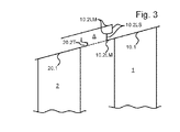
- Fig. 3 shows in Fig. 2 corresponding representation of a part of a gas turbine stage according to a modified embodiment of the present invention.
- Corresponding elements are denoted by identical reference numerals, so that reference is made in full to the above explanations and will be discussed below only on the differences in the modification.
- the radially outer blade platforms are inclined against the turbine axis to represent a divergent flow channel.
- the explanations also apply in the same way to convergent flow channels (not shown), in particular in compressor or compressor stages.
- the radially outer blade platform in the form of a shroud in its trailing edge gap region 20.2T an annular flange with radially opposite lateral surfaces, as already described above with respect to the trailing edge gap region 10.2T of the guide vane 1 of Fig. 1 was explained.
- the trailing edge gap portion 20.2T can on its radially inner (bottom in Fig. 3 ) and / or outer lateral surface have, in particular the same, waviness.
- the leading edge gap region includes a radially inner annular flange in a radially outer groove-like recess of the gas turbine housing. Accordingly, the leading edge gap region has three lateral surfaces 10.2LM, the radially inner and the outer lateral surface of the annular flange and the lateral surface of the recess itself, and two end surfaces 10.LS, that of the annular flange and that of the recess itself.
- Each of these sections 10.2LM, 10.2LS can each have a ripple in radial (10.2LM) or axial (10.2LS) direction.
- Several, in particular all sections of the gap region can also have a waviness.
- the modification of the Fig. 3 in a representation show different variants where a contour of a gap region in the radial and / or axial direction can vary over the circumference.
Landscapes
- Engineering & Computer Science (AREA)
- Physics & Mathematics (AREA)
- Fluid Mechanics (AREA)
- Mechanical Engineering (AREA)
- General Engineering & Computer Science (AREA)
- Structures Of Non-Positive Displacement Pumps (AREA)
- Turbine Rotor Nozzle Sealing (AREA)
Priority Applications (3)
| Application Number | Priority Date | Filing Date | Title |
|---|---|---|---|
| EP11194433.6A EP2607625B1 (fr) | 2011-12-20 | 2011-12-20 | Turbomachine et étage de turbomachine |
| ES11194433T ES2891562T3 (es) | 2011-12-20 | 2011-12-20 | Turbomaquinaria y etapa de turbomaquinaria |
| US13/687,789 US20130156562A1 (en) | 2011-12-20 | 2012-11-28 | Turbomachine and turbomachine stage |
Applications Claiming Priority (1)
| Application Number | Priority Date | Filing Date | Title |
|---|---|---|---|
| EP11194433.6A EP2607625B1 (fr) | 2011-12-20 | 2011-12-20 | Turbomachine et étage de turbomachine |
Publications (2)
| Publication Number | Publication Date |
|---|---|
| EP2607625A1 true EP2607625A1 (fr) | 2013-06-26 |
| EP2607625B1 EP2607625B1 (fr) | 2021-09-08 |
Family
ID=45442918
Family Applications (1)
| Application Number | Title | Priority Date | Filing Date |
|---|---|---|---|
| EP11194433.6A Not-in-force EP2607625B1 (fr) | 2011-12-20 | 2011-12-20 | Turbomachine et étage de turbomachine |
Country Status (3)
| Country | Link |
|---|---|
| US (1) | US20130156562A1 (fr) |
| EP (1) | EP2607625B1 (fr) |
| ES (1) | ES2891562T3 (fr) |
Cited By (1)
| Publication number | Priority date | Publication date | Assignee | Title |
|---|---|---|---|---|
| EP2990600A1 (fr) * | 2014-08-29 | 2016-03-02 | MTU Aero Engines GmbH | Ensemble de turbine à gaz |
Families Citing this family (6)
| Publication number | Priority date | Publication date | Assignee | Title |
|---|---|---|---|---|
| US20140140822A1 (en) * | 2012-11-16 | 2014-05-22 | General Electric Company | Contoured Stator Shroud |
| ES2819128T3 (es) * | 2017-03-03 | 2021-04-15 | MTU Aero Engines AG | Contorneo de una plataforma de una rejilla de paletas |
| KR102000281B1 (ko) * | 2017-10-11 | 2019-07-15 | 두산중공업 주식회사 | 압축기 및 이를 포함하는 가스 터빈 |
| GB201820400D0 (en) * | 2018-12-14 | 2019-01-30 | Rolls Royce Plc | Ice crystal protection for a gas turbine engine |
| FR3106627B1 (fr) * | 2020-01-24 | 2023-03-17 | Safran Aircraft Engines | Basculement en vagues aux entrefers rotor-stator dans un compresseur de turbomachine |
| US12442304B1 (en) | 2025-03-12 | 2025-10-14 | General Electric Company | Gas turbine engine with bow wave mitigation |
Citations (8)
| Publication number | Priority date | Publication date | Assignee | Title |
|---|---|---|---|---|
| EP1067273A1 (fr) * | 1999-07-06 | 2001-01-10 | ROLLS-ROYCE plc | Configuration d'une bande de recouvrement des aubes de turbine |
| WO2004113685A1 (fr) * | 2003-06-21 | 2004-12-29 | Alstom Technology Ltd | Configuration de la paroi laterale d'un canal d'ecoulement a deviation |
| EP1515000A1 (fr) * | 2003-09-09 | 2005-03-16 | ALSTOM Technology Ltd | Aubage d'une turbomachine avec un carenage contouré |
| US20070128021A1 (en) * | 2005-04-01 | 2007-06-07 | General Electric Company | Turbine nozzle with purge cavity blend |
| EP2003292A2 (fr) * | 2007-06-14 | 2008-12-17 | Rolls-Royce Deutschland Ltd & Co KG | Bande de recouvrement d'aube dotée d'un rebord |
| EP2136033A1 (fr) * | 2007-03-29 | 2009-12-23 | IHI Corporation | Paroi de turbomachine et turbomachine |
| EP2369138A1 (fr) * | 2010-03-23 | 2011-09-28 | United Technologies Corporation | Moteur à turbine à gaz doté d'une plateforme de pale de rotor contourée à surface non axisymétrique |
| EP2372102A2 (fr) | 2010-04-02 | 2011-10-05 | United Technologies Corporation | Plate-forme des pales de rotor d'une turbine à gaz |
-
2011
- 2011-12-20 EP EP11194433.6A patent/EP2607625B1/fr not_active Not-in-force
- 2011-12-20 ES ES11194433T patent/ES2891562T3/es active Active
-
2012
- 2012-11-28 US US13/687,789 patent/US20130156562A1/en not_active Abandoned
Patent Citations (8)
| Publication number | Priority date | Publication date | Assignee | Title |
|---|---|---|---|---|
| EP1067273A1 (fr) * | 1999-07-06 | 2001-01-10 | ROLLS-ROYCE plc | Configuration d'une bande de recouvrement des aubes de turbine |
| WO2004113685A1 (fr) * | 2003-06-21 | 2004-12-29 | Alstom Technology Ltd | Configuration de la paroi laterale d'un canal d'ecoulement a deviation |
| EP1515000A1 (fr) * | 2003-09-09 | 2005-03-16 | ALSTOM Technology Ltd | Aubage d'une turbomachine avec un carenage contouré |
| US20070128021A1 (en) * | 2005-04-01 | 2007-06-07 | General Electric Company | Turbine nozzle with purge cavity blend |
| EP2136033A1 (fr) * | 2007-03-29 | 2009-12-23 | IHI Corporation | Paroi de turbomachine et turbomachine |
| EP2003292A2 (fr) * | 2007-06-14 | 2008-12-17 | Rolls-Royce Deutschland Ltd & Co KG | Bande de recouvrement d'aube dotée d'un rebord |
| EP2369138A1 (fr) * | 2010-03-23 | 2011-09-28 | United Technologies Corporation | Moteur à turbine à gaz doté d'une plateforme de pale de rotor contourée à surface non axisymétrique |
| EP2372102A2 (fr) | 2010-04-02 | 2011-10-05 | United Technologies Corporation | Plate-forme des pales de rotor d'une turbine à gaz |
Cited By (2)
| Publication number | Priority date | Publication date | Assignee | Title |
|---|---|---|---|---|
| EP2990600A1 (fr) * | 2014-08-29 | 2016-03-02 | MTU Aero Engines GmbH | Ensemble de turbine à gaz |
| US9822706B2 (en) | 2014-08-29 | 2017-11-21 | MTU Aero Engines AG | Gas turbine subassembly |
Also Published As
| Publication number | Publication date |
|---|---|
| US20130156562A1 (en) | 2013-06-20 |
| ES2891562T3 (es) | 2022-01-28 |
| EP2607625B1 (fr) | 2021-09-08 |
Similar Documents
| Publication | Publication Date | Title |
|---|---|---|
| EP2806102B1 (fr) | Aubage statorique de turbomachine et turbomachine associée | |
| EP2746533B1 (fr) | Grille d'aube et turbomachine | |
| DE102008055824B4 (de) | Dampfturbine | |
| EP2696029B1 (fr) | Grille d'aube avec définition de contour de la paroi latérale et turbomachine | |
| EP2927503B1 (fr) | Compresseur de turbine à gaz, moteur d'avion et méthode de dimensionnement | |
| EP2789802B1 (fr) | Étage d'aubes pour une turbomachine et procédé associé de fabrication | |
| EP2607625B1 (fr) | Turbomachine et étage de turbomachine | |
| EP1632662B1 (fr) | Turbomachine avec soutirage | |
| EP3225781B1 (fr) | Canal d'aube, grille d'aube et turbomachine | |
| EP2835499B1 (fr) | Grille d'aubes et turbomachine associée | |
| EP2299124A1 (fr) | Aube de rotor pour un compresseur axial | |
| EP2294286B1 (fr) | Rotor avex aubes mobiles carenées d'une turbomachine | |
| CH697806A2 (de) | Turbinenschaufel-Deckbandkantenprofil. | |
| EP2787172A2 (fr) | Grille d'aubes avec définition de contour de la paroi latérale et turbomachine | |
| EP2626514A1 (fr) | Turbomachine | |
| EP2558685B1 (fr) | Aube directrice | |
| EP2626512A1 (fr) | Turbomachine | |
| EP2505851B1 (fr) | Aubage de stator pour un compresseur axial dans une turbomachine | |
| EP2607626B1 (fr) | Turbomachine et étage de turbomachine | |
| DE102015206384A1 (de) | Deckbandanordnung einer Schaufelreihe von Stator- oder Rotorschaufeln | |
| EP2696042B1 (fr) | Turbomachine avec au moins un stator | |
| EP3358135B1 (fr) | Contournage d'une plate-forme de grille d'aube | |
| EP2410131A2 (fr) | Rotor d'une turbomachine | |
| EP3401504A1 (fr) | Grille d'aube | |
| EP2871368A1 (fr) | Compresseur de turbine à gaz |
Legal Events
| Date | Code | Title | Description |
|---|---|---|---|
| 17P | Request for examination filed |
Effective date: 20120924 |
|
| AK | Designated contracting states |
Kind code of ref document: A1 Designated state(s): AL AT BE BG CH CY CZ DE DK EE ES FI FR GB GR HR HU IE IS IT LI LT LU LV MC MK MT NL NO PL PT RO RS SE SI SK SM TR |
|
| AX | Request for extension of the european patent |
Extension state: BA ME |
|
| PUAI | Public reference made under article 153(3) epc to a published international application that has entered the european phase |
Free format text: ORIGINAL CODE: 0009012 |
|
| RAP1 | Party data changed (applicant data changed or rights of an application transferred) |
Owner name: MTU AERO ENGINES AG |
|
| 17Q | First examination report despatched |
Effective date: 20140722 |
|
| STAA | Information on the status of an ep patent application or granted ep patent |
Free format text: STATUS: EXAMINATION IS IN PROGRESS |
|
| RIN1 | Information on inventor provided before grant (corrected) |
Inventor name: MAHLE, INGA Inventor name: ENGEL, KARL Inventor name: KOERBER, KAI Inventor name: GIER, JOCHEN |
|
| GRAP | Despatch of communication of intention to grant a patent |
Free format text: ORIGINAL CODE: EPIDOSNIGR1 |
|
| STAA | Information on the status of an ep patent application or granted ep patent |
Free format text: STATUS: GRANT OF PATENT IS INTENDED |
|
| INTG | Intention to grant announced |
Effective date: 20210330 |
|
| GRAS | Grant fee paid |
Free format text: ORIGINAL CODE: EPIDOSNIGR3 |
|
| GRAA | (expected) grant |
Free format text: ORIGINAL CODE: 0009210 |
|
| STAA | Information on the status of an ep patent application or granted ep patent |
Free format text: STATUS: THE PATENT HAS BEEN GRANTED |
|
| AK | Designated contracting states |
Kind code of ref document: B1 Designated state(s): AL AT BE BG CH CY CZ DE DK EE ES FI FR GB GR HR HU IE IS IT LI LT LU LV MC MK MT NL NO PL PT RO RS SE SI SK SM TR |
|
| REG | Reference to a national code |
Ref country code: GB Ref legal event code: FG4D Free format text: NOT ENGLISH |
|
| REG | Reference to a national code |
Ref country code: CH Ref legal event code: EP Ref country code: AT Ref legal event code: REF Ref document number: 1428769 Country of ref document: AT Kind code of ref document: T Effective date: 20210915 |
|
| REG | Reference to a national code |
Ref country code: DE Ref legal event code: R096 Ref document number: 502011017224 Country of ref document: DE |
|
| REG | Reference to a national code |
Ref country code: IE Ref legal event code: FG4D Free format text: LANGUAGE OF EP DOCUMENT: GERMAN |
|
| REG | Reference to a national code |
Ref country code: LT Ref legal event code: MG9D |
|
| REG | Reference to a national code |
Ref country code: NL Ref legal event code: MP Effective date: 20210908 |
|
| REG | Reference to a national code |
Ref country code: ES Ref legal event code: FG2A Ref document number: 2891562 Country of ref document: ES Kind code of ref document: T3 Effective date: 20220128 |
|
| PG25 | Lapsed in a contracting state [announced via postgrant information from national office to epo] |
Ref country code: HR Free format text: LAPSE BECAUSE OF FAILURE TO SUBMIT A TRANSLATION OF THE DESCRIPTION OR TO PAY THE FEE WITHIN THE PRESCRIBED TIME-LIMIT Effective date: 20210908 Ref country code: SE Free format text: LAPSE BECAUSE OF FAILURE TO SUBMIT A TRANSLATION OF THE DESCRIPTION OR TO PAY THE FEE WITHIN THE PRESCRIBED TIME-LIMIT Effective date: 20210908 Ref country code: RS Free format text: LAPSE BECAUSE OF FAILURE TO SUBMIT A TRANSLATION OF THE DESCRIPTION OR TO PAY THE FEE WITHIN THE PRESCRIBED TIME-LIMIT Effective date: 20210908 Ref country code: NO Free format text: LAPSE BECAUSE OF FAILURE TO SUBMIT A TRANSLATION OF THE DESCRIPTION OR TO PAY THE FEE WITHIN THE PRESCRIBED TIME-LIMIT Effective date: 20211208 Ref country code: FI Free format text: LAPSE BECAUSE OF FAILURE TO SUBMIT A TRANSLATION OF THE DESCRIPTION OR TO PAY THE FEE WITHIN THE PRESCRIBED TIME-LIMIT Effective date: 20210908 Ref country code: BG Free format text: LAPSE BECAUSE OF FAILURE TO SUBMIT A TRANSLATION OF THE DESCRIPTION OR TO PAY THE FEE WITHIN THE PRESCRIBED TIME-LIMIT Effective date: 20211208 Ref country code: LT Free format text: LAPSE BECAUSE OF FAILURE TO SUBMIT A TRANSLATION OF THE DESCRIPTION OR TO PAY THE FEE WITHIN THE PRESCRIBED TIME-LIMIT Effective date: 20210908 |
|
| PG25 | Lapsed in a contracting state [announced via postgrant information from national office to epo] |
Ref country code: LV Free format text: LAPSE BECAUSE OF FAILURE TO SUBMIT A TRANSLATION OF THE DESCRIPTION OR TO PAY THE FEE WITHIN THE PRESCRIBED TIME-LIMIT Effective date: 20210908 Ref country code: GR Free format text: LAPSE BECAUSE OF FAILURE TO SUBMIT A TRANSLATION OF THE DESCRIPTION OR TO PAY THE FEE WITHIN THE PRESCRIBED TIME-LIMIT Effective date: 20211209 |
|
| PG25 | Lapsed in a contracting state [announced via postgrant information from national office to epo] |
Ref country code: IS Free format text: LAPSE BECAUSE OF FAILURE TO SUBMIT A TRANSLATION OF THE DESCRIPTION OR TO PAY THE FEE WITHIN THE PRESCRIBED TIME-LIMIT Effective date: 20220108 Ref country code: SM Free format text: LAPSE BECAUSE OF FAILURE TO SUBMIT A TRANSLATION OF THE DESCRIPTION OR TO PAY THE FEE WITHIN THE PRESCRIBED TIME-LIMIT Effective date: 20210908 Ref country code: SK Free format text: LAPSE BECAUSE OF FAILURE TO SUBMIT A TRANSLATION OF THE DESCRIPTION OR TO PAY THE FEE WITHIN THE PRESCRIBED TIME-LIMIT Effective date: 20210908 Ref country code: RO Free format text: LAPSE BECAUSE OF FAILURE TO SUBMIT A TRANSLATION OF THE DESCRIPTION OR TO PAY THE FEE WITHIN THE PRESCRIBED TIME-LIMIT Effective date: 20210908 Ref country code: PT Free format text: LAPSE BECAUSE OF FAILURE TO SUBMIT A TRANSLATION OF THE DESCRIPTION OR TO PAY THE FEE WITHIN THE PRESCRIBED TIME-LIMIT Effective date: 20220110 Ref country code: PL Free format text: LAPSE BECAUSE OF FAILURE TO SUBMIT A TRANSLATION OF THE DESCRIPTION OR TO PAY THE FEE WITHIN THE PRESCRIBED TIME-LIMIT Effective date: 20210908 Ref country code: NL Free format text: LAPSE BECAUSE OF FAILURE TO SUBMIT A TRANSLATION OF THE DESCRIPTION OR TO PAY THE FEE WITHIN THE PRESCRIBED TIME-LIMIT Effective date: 20210908 Ref country code: EE Free format text: LAPSE BECAUSE OF FAILURE TO SUBMIT A TRANSLATION OF THE DESCRIPTION OR TO PAY THE FEE WITHIN THE PRESCRIBED TIME-LIMIT Effective date: 20210908 Ref country code: CZ Free format text: LAPSE BECAUSE OF FAILURE TO SUBMIT A TRANSLATION OF THE DESCRIPTION OR TO PAY THE FEE WITHIN THE PRESCRIBED TIME-LIMIT Effective date: 20210908 Ref country code: AL Free format text: LAPSE BECAUSE OF FAILURE TO SUBMIT A TRANSLATION OF THE DESCRIPTION OR TO PAY THE FEE WITHIN THE PRESCRIBED TIME-LIMIT Effective date: 20210908 |
|
| REG | Reference to a national code |
Ref country code: DE Ref legal event code: R097 Ref document number: 502011017224 Country of ref document: DE |
|
| PLBE | No opposition filed within time limit |
Free format text: ORIGINAL CODE: 0009261 |
|
| STAA | Information on the status of an ep patent application or granted ep patent |
Free format text: STATUS: NO OPPOSITION FILED WITHIN TIME LIMIT |
|
| PG25 | Lapsed in a contracting state [announced via postgrant information from national office to epo] |
Ref country code: MC Free format text: LAPSE BECAUSE OF FAILURE TO SUBMIT A TRANSLATION OF THE DESCRIPTION OR TO PAY THE FEE WITHIN THE PRESCRIBED TIME-LIMIT Effective date: 20210908 Ref country code: DK Free format text: LAPSE BECAUSE OF FAILURE TO SUBMIT A TRANSLATION OF THE DESCRIPTION OR TO PAY THE FEE WITHIN THE PRESCRIBED TIME-LIMIT Effective date: 20210908 |
|
| REG | Reference to a national code |
Ref country code: CH Ref legal event code: PL |
|
| 26N | No opposition filed |
Effective date: 20220609 |
|
| PG25 | Lapsed in a contracting state [announced via postgrant information from national office to epo] |
Ref country code: SI Free format text: LAPSE BECAUSE OF FAILURE TO SUBMIT A TRANSLATION OF THE DESCRIPTION OR TO PAY THE FEE WITHIN THE PRESCRIBED TIME-LIMIT Effective date: 20210908 |
|
| REG | Reference to a national code |
Ref country code: BE Ref legal event code: MM Effective date: 20211231 |
|
| PG25 | Lapsed in a contracting state [announced via postgrant information from national office to epo] |
Ref country code: LU Free format text: LAPSE BECAUSE OF NON-PAYMENT OF DUE FEES Effective date: 20211220 Ref country code: IE Free format text: LAPSE BECAUSE OF NON-PAYMENT OF DUE FEES Effective date: 20211220 |
|
| PG25 | Lapsed in a contracting state [announced via postgrant information from national office to epo] |
Ref country code: BE Free format text: LAPSE BECAUSE OF NON-PAYMENT OF DUE FEES Effective date: 20211231 |
|
| PG25 | Lapsed in a contracting state [announced via postgrant information from national office to epo] |
Ref country code: LI Free format text: LAPSE BECAUSE OF NON-PAYMENT OF DUE FEES Effective date: 20211231 Ref country code: CH Free format text: LAPSE BECAUSE OF NON-PAYMENT OF DUE FEES Effective date: 20211231 |
|
| PG25 | Lapsed in a contracting state [announced via postgrant information from national office to epo] |
Ref country code: IT Free format text: LAPSE BECAUSE OF FAILURE TO SUBMIT A TRANSLATION OF THE DESCRIPTION OR TO PAY THE FEE WITHIN THE PRESCRIBED TIME-LIMIT Effective date: 20210908 |
|
| REG | Reference to a national code |
Ref country code: AT Ref legal event code: MM01 Ref document number: 1428769 Country of ref document: AT Kind code of ref document: T Effective date: 20211220 |
|
| PG25 | Lapsed in a contracting state [announced via postgrant information from national office to epo] |
Ref country code: AT Free format text: LAPSE BECAUSE OF NON-PAYMENT OF DUE FEES Effective date: 20211220 |
|
| PG25 | Lapsed in a contracting state [announced via postgrant information from national office to epo] |
Ref country code: HU Free format text: LAPSE BECAUSE OF FAILURE TO SUBMIT A TRANSLATION OF THE DESCRIPTION OR TO PAY THE FEE WITHIN THE PRESCRIBED TIME-LIMIT; INVALID AB INITIO Effective date: 20111220 Ref country code: CY Free format text: LAPSE BECAUSE OF FAILURE TO SUBMIT A TRANSLATION OF THE DESCRIPTION OR TO PAY THE FEE WITHIN THE PRESCRIBED TIME-LIMIT Effective date: 20210908 |
|
| PGFP | Annual fee paid to national office [announced via postgrant information from national office to epo] |
Ref country code: GB Payment date: 20231220 Year of fee payment: 13 |
|
| PGFP | Annual fee paid to national office [announced via postgrant information from national office to epo] |
Ref country code: FR Payment date: 20231219 Year of fee payment: 13 Ref country code: DE Payment date: 20231214 Year of fee payment: 13 |
|
| PGFP | Annual fee paid to national office [announced via postgrant information from national office to epo] |
Ref country code: ES Payment date: 20240118 Year of fee payment: 13 |
|
| PG25 | Lapsed in a contracting state [announced via postgrant information from national office to epo] |
Ref country code: MK Free format text: LAPSE BECAUSE OF FAILURE TO SUBMIT A TRANSLATION OF THE DESCRIPTION OR TO PAY THE FEE WITHIN THE PRESCRIBED TIME-LIMIT Effective date: 20210908 |
|
| PG25 | Lapsed in a contracting state [announced via postgrant information from national office to epo] |
Ref country code: MT Free format text: LAPSE BECAUSE OF FAILURE TO SUBMIT A TRANSLATION OF THE DESCRIPTION OR TO PAY THE FEE WITHIN THE PRESCRIBED TIME-LIMIT Effective date: 20210908 |
|
| REG | Reference to a national code |
Ref country code: DE Ref legal event code: R119 Ref document number: 502011017224 Country of ref document: DE |
|
| GBPC | Gb: european patent ceased through non-payment of renewal fee |
Effective date: 20241220 |
|
| PG25 | Lapsed in a contracting state [announced via postgrant information from national office to epo] |
Ref country code: DE Free format text: LAPSE BECAUSE OF NON-PAYMENT OF DUE FEES Effective date: 20250701 |
|
| PG25 | Lapsed in a contracting state [announced via postgrant information from national office to epo] |
Ref country code: GB Free format text: LAPSE BECAUSE OF NON-PAYMENT OF DUE FEES Effective date: 20241220 |
|
| PG25 | Lapsed in a contracting state [announced via postgrant information from national office to epo] |
Ref country code: FR Free format text: LAPSE BECAUSE OF NON-PAYMENT OF DUE FEES Effective date: 20241231 |
|
| PG25 | Lapsed in a contracting state [announced via postgrant information from national office to epo] |
Ref country code: TR Free format text: LAPSE BECAUSE OF FAILURE TO SUBMIT A TRANSLATION OF THE DESCRIPTION OR TO PAY THE FEE WITHIN THE PRESCRIBED TIME-LIMIT Effective date: 20210908 |
|
| REG | Reference to a national code |
Ref country code: ES Ref legal event code: FD2A Effective date: 20260202 |
|
| PG25 | Lapsed in a contracting state [announced via postgrant information from national office to epo] |
Ref country code: ES Free format text: LAPSE BECAUSE OF NON-PAYMENT OF DUE FEES Effective date: 20241221 |