EP2003304A1 - Piston doté d'une cavité pour un moteur à combustion interne et procédé destiné à la formation d'un mélange en utilisant un dispositif de vaporisation et un tel piston - Google Patents
Piston doté d'une cavité pour un moteur à combustion interne et procédé destiné à la formation d'un mélange en utilisant un dispositif de vaporisation et un tel piston Download PDFInfo
- Publication number
- EP2003304A1 EP2003304A1 EP07110323A EP07110323A EP2003304A1 EP 2003304 A1 EP2003304 A1 EP 2003304A1 EP 07110323 A EP07110323 A EP 07110323A EP 07110323 A EP07110323 A EP 07110323A EP 2003304 A1 EP2003304 A1 EP 2003304A1
- Authority
- EP
- European Patent Office
- Prior art keywords
- piston
- fuel
- trough
- convex portion
- injection
- Prior art date
- Legal status (The legal status is an assumption and is not a legal conclusion. Google has not performed a legal analysis and makes no representation as to the accuracy of the status listed.)
- Granted
Links
- 238000000034 method Methods 0.000 title claims abstract description 76
- 239000000203 mixture Substances 0.000 title claims abstract description 54
- 238000002485 combustion reaction Methods 0.000 title claims description 79
- 238000002347 injection Methods 0.000 title claims description 55
- 239000007924 injection Substances 0.000 title claims description 55
- 239000000446 fuel Substances 0.000 claims abstract description 52
- 230000015572 biosynthetic process Effects 0.000 abstract description 17
- 230000014759 maintenance of location Effects 0.000 abstract 1
- MWUXSHHQAYIFBG-UHFFFAOYSA-N Nitric oxide Chemical compound O=[N] MWUXSHHQAYIFBG-UHFFFAOYSA-N 0.000 description 60
- 239000004071 soot Substances 0.000 description 14
- 238000002360 preparation method Methods 0.000 description 12
- 239000007789 gas Substances 0.000 description 11
- 238000000265 homogenisation Methods 0.000 description 7
- 230000006835 compression Effects 0.000 description 6
- 238000007906 compression Methods 0.000 description 6
- 229930195733 hydrocarbon Natural products 0.000 description 6
- 150000002430 hydrocarbons Chemical class 0.000 description 6
- 230000007704 transition Effects 0.000 description 6
- 239000002283 diesel fuel Substances 0.000 description 4
- 239000002245 particle Substances 0.000 description 4
- 239000003054 catalyst Substances 0.000 description 3
- 238000006243 chemical reaction Methods 0.000 description 3
- 239000003638 chemical reducing agent Substances 0.000 description 3
- 238000009792 diffusion process Methods 0.000 description 3
- 239000003344 environmental pollutant Substances 0.000 description 3
- 238000002156 mixing Methods 0.000 description 3
- 231100000719 pollutant Toxicity 0.000 description 3
- 230000008929 regeneration Effects 0.000 description 3
- 238000011069 regeneration method Methods 0.000 description 3
- QGZKDVFQNNGYKY-UHFFFAOYSA-N Ammonia Chemical compound N QGZKDVFQNNGYKY-UHFFFAOYSA-N 0.000 description 2
- 230000003197 catalytic effect Effects 0.000 description 2
- 230000007423 decrease Effects 0.000 description 2
- 230000018109 developmental process Effects 0.000 description 2
- 238000010790 dilution Methods 0.000 description 2
- 239000012895 dilution Substances 0.000 description 2
- 239000008240 homogeneous mixture Substances 0.000 description 2
- 239000000479 mixture part Substances 0.000 description 2
- 230000002028 premature Effects 0.000 description 2
- 238000003908 quality control method Methods 0.000 description 2
- 241000272525 Anas platyrhynchos Species 0.000 description 1
- 241000978750 Havardia Species 0.000 description 1
- XSQUKJJJFZCRTK-UHFFFAOYSA-N Urea Chemical compound NC(N)=O XSQUKJJJFZCRTK-UHFFFAOYSA-N 0.000 description 1
- 230000001133 acceleration Effects 0.000 description 1
- 230000002411 adverse Effects 0.000 description 1
- 229910021529 ammonia Inorganic materials 0.000 description 1
- QVGXLLKOCUKJST-UHFFFAOYSA-N atomic oxygen Chemical compound [O] QVGXLLKOCUKJST-UHFFFAOYSA-N 0.000 description 1
- 239000004202 carbamide Substances 0.000 description 1
- 239000011248 coating agent Substances 0.000 description 1
- 238000000576 coating method Methods 0.000 description 1
- 238000007796 conventional method Methods 0.000 description 1
- 230000003247 decreasing effect Effects 0.000 description 1
- 230000003111 delayed effect Effects 0.000 description 1
- 238000006073 displacement reaction Methods 0.000 description 1
- 230000000694 effects Effects 0.000 description 1
- 238000005516 engineering process Methods 0.000 description 1
- 238000001704 evaporation Methods 0.000 description 1
- 230000008020 evaporation Effects 0.000 description 1
- 230000002349 favourable effect Effects 0.000 description 1
- 230000005484 gravity Effects 0.000 description 1
- 230000000977 initiatory effect Effects 0.000 description 1
- 239000007788 liquid Substances 0.000 description 1
- 229910000510 noble metal Inorganic materials 0.000 description 1
- 239000001301 oxygen Substances 0.000 description 1
- 229910052760 oxygen Inorganic materials 0.000 description 1
- 238000004806 packaging method and process Methods 0.000 description 1
- 238000004064 recycling Methods 0.000 description 1
- 238000000926 separation method Methods 0.000 description 1
Images


Classifications
-
- F—MECHANICAL ENGINEERING; LIGHTING; HEATING; WEAPONS; BLASTING
- F02—COMBUSTION ENGINES; HOT-GAS OR COMBUSTION-PRODUCT ENGINE PLANTS
- F02B—INTERNAL-COMBUSTION PISTON ENGINES; COMBUSTION ENGINES IN GENERAL
- F02B23/00—Other engines characterised by special shape or construction of combustion chambers to improve operation
- F02B23/02—Other engines characterised by special shape or construction of combustion chambers to improve operation with compression ignition
- F02B23/06—Other engines characterised by special shape or construction of combustion chambers to improve operation with compression ignition the combustion space being arranged in working piston
- F02B23/0672—Omega-piston bowl, i.e. the combustion space having a central projection pointing towards the cylinder head and the surrounding wall being inclined towards the cylinder center axis
-
- F—MECHANICAL ENGINEERING; LIGHTING; HEATING; WEAPONS; BLASTING
- F02—COMBUSTION ENGINES; HOT-GAS OR COMBUSTION-PRODUCT ENGINE PLANTS
- F02B—INTERNAL-COMBUSTION PISTON ENGINES; COMBUSTION ENGINES IN GENERAL
- F02B23/00—Other engines characterised by special shape or construction of combustion chambers to improve operation
- F02B23/02—Other engines characterised by special shape or construction of combustion chambers to improve operation with compression ignition
- F02B23/06—Other engines characterised by special shape or construction of combustion chambers to improve operation with compression ignition the combustion space being arranged in working piston
- F02B23/0645—Details related to the fuel injector or the fuel spray
-
- Y—GENERAL TAGGING OF NEW TECHNOLOGICAL DEVELOPMENTS; GENERAL TAGGING OF CROSS-SECTIONAL TECHNOLOGIES SPANNING OVER SEVERAL SECTIONS OF THE IPC; TECHNICAL SUBJECTS COVERED BY FORMER USPC CROSS-REFERENCE ART COLLECTIONS [XRACs] AND DIGESTS
- Y02—TECHNOLOGIES OR APPLICATIONS FOR MITIGATION OR ADAPTATION AGAINST CLIMATE CHANGE
- Y02T—CLIMATE CHANGE MITIGATION TECHNOLOGIES RELATED TO TRANSPORTATION
- Y02T10/00—Road transport of goods or passengers
- Y02T10/10—Internal combustion engine [ICE] based vehicles
- Y02T10/12—Improving ICE efficiencies
Definitions
- the invention relates to a piston having a piston head and a piston recess provided in the piston crown, in particular for an internal combustion engine, which allows operation in two different operating modes, which - during operation of the internal combustion engine - is translationally movable along a piston longitudinal axis and in which the piston recess has an omega-shaped basic shape.
- the invention relates to a method for forming a fuel-air mixture using an injector and a piston of the aforementioned type, wherein at least one injection of fuel is made directly into the combustion chamber of an internal combustion engine by means of the injection device, wherein the combustion chamber the piston crown of the piston and a cylinder tube is mitbe interpersonal.
- the market share of small high-speed diesel engines is growing steadily. The reasons for this are on the one hand in the low fuel consumption and on the other hand in the comparatively good performance of modern diesel engines of the younger generations.
- the low fuel consumption results, among other things, from a high compression ratio and low charge cycle losses due to the quality control of the diesel engine.
- the nitrogen oxides contained in the exhaust can inherently - ie due to the lack of reducing agents - can not be reduced without additional measures.
- selective catalysts - so-called SCR catalysts - are used, in which targeted reducing agents are introduced into the exhaust gas to selectively reduce the nitrogen oxides.
- SCR catalysts - As a reducing agent in addition to ammonia and urea also unburned hydrocarbons are used. The latter is also called HC enrichment.
- the nitrogen oxides can also be counteracted with so-called nitrogen oxide storage catalysts.
- the nitrogen oxides are first collected during a storage phase in the catalytic converter, in order then to be reduced during a regeneration phase by means of a substoichiometric operation (for example ⁇ ⁇ 0.95) of the internal combustion engine.
- Storage catalytic converters require the combustion of a homogeneous mixture to avoid high levels of soot emissions, which is why they are suitable for lean-burn gasoline engines, but especially not for direct-injection diesel engines.
- An internal engine measure known from the prior art for reducing nitrogen oxide emissions consists in reducing the combustion temperatures, in particular the process peak temperatures. As the process temperatures decrease, the formation of nitrogen oxides also decreases.
- Lower process temperatures can be realized for example by the recycling of hot exhaust gas (EGR) and / or intercooling.
- EGR hot exhaust gas
- Another disadvantage of the direct injection diesel engine process is the soot emissions due to the inhomogeneity of the fuel-air mixture.
- regenerable particulate filters are used in the prior art, which filter the soot particles from the exhaust gas and store, these soot particles are intermittently burned in the regeneration of the filter.
- soot To comply with future limits, the formation of soot must already be counteracted during the combustion, which can be achieved by a sufficiently large excess of air and an optimized mixture formation with the greatest possible homogenization.
- the Otto engine method is characterized by a mixture compression, a homogeneous mixture, a spark ignition, and the quantity control, whereas the diesel engine process is characterized by an air compression, an inhomogeneous mixture, auto-ignition and quality control.
- LTC Low Temperature Combustion
- HCCI Homogeneous-Charge Compression Ignition
- CAI-process C ontrolled A uto- gnition I
- the fuel is burned in excess of air - that is, more than stoichiometrically.
- the lean-burn diesel engine has comparatively low nitrogen oxide emissions (NO x ) due to the highly diluted homogenized fuel-air mixture and the associated low combustion temperatures and also virtually no soot emissions due to the lean homogenized mixture.
- the thermal efficiency of the HCCI process is high because the homogenized mixture burns volumetrically, i. H. no diffusion flame propagates through the combustion chamber, but is ignited and burned in the entire combustion chamber almost simultaneously at a constant volume.
- the diesel engine HCCI process also has disadvantages similar to those of the Otto engine HCCI process.
- the main disadvantage of the HCCI method is that this method can not be used in all operating points of an internal combustion engine, so that the - already described above - benefits only in a small area of the engine map (load over speed) can be used.
- an internal combustion engine can not be operated exclusively by the HCCI method, but basically a hybrid drive is required, ie, an internal combustion engine, which allows operation in two different operating modes to the internal combustion engine in the operating points where the HCCI method fails to operate anyway.
- a conventional diesel engine process is used Use in which spreads a self-ignition, a diffusion flame in the combustion chamber.
- the HCCI method can not be used at high loads and high speeds.
- the restrictions in the application of the HCCI method arise in principle from the control of the ignition timing d. H. the auto-ignition and the control of the burning speed d. H. the burning process.
- the auto-ignition and the burning speed are very sensitive to changes in the temperature of the cylinder charge, changes in the air ratio and speed changes.
- the piston bowl 104 of a conventional piston 101 has according to FIG. 1 a concave portion 108, which serves to form the omega-shaped basic shape of the piston recess 104, wherein the piston longitudinal axis 102 facing trough surface 105 has two convex Partial regions 107a, 107b, of which a first portion 107a forms the trough edge 106 and a second portion 107b projects into the piston recess 104.
- the two convex portions 107a, 107b are connected to each other via a cylindrical wall portion.
- the fuel according to FIG. 1 injected in such a way that the injection jets 109 are directed to the second convex portion 107b, wherein the individual injection jets 109 split upon impact with the trough surface 105 in a plurality of divergent fuel partial beams, partially accelerated out of the piston recess 104 and partially deflected thereby mixed the fuel is spacious with the air in the combustion chamber, so that a good use of air is ensured.
- a disadvantage of this conventional method for mixture formation is that - arise on the one hand due to the very dynamic distribution of the fuel in the combustion chamber and on the other hand due to the small radius of curvature of the trough edge - turbulence in the fuel-air mixture, especially in the region of the trough edge at the transition into the Crushing zone, which in a few, locally narrow areas of the combustion chamber, the mixture formation progresses so far that local conditions for auto-ignition are present, whereas in many areas of the combustion chamber is still a very inhomogeneous mixture. For this reason, the self-ignition is initiated earlier than is desirable, in particular with regard to a good emission behavior of the internal combustion engine. It would be more advantageous to increase the ignition delay d. H. ignite later and further homogenize the mixture before initiating auto-ignition.
- Another object of the present invention is to provide a method of forming a fuel-air mixture using an injector and such a piston.
- the first sub-task is solved by a piston with piston crown and provided in the piston crown piston recess, in particular for an internal combustion engine, which allows operation in two different operating modes, which - during operation of the internal combustion engine - is translationally movable along a piston longitudinal axis and wherein the piston recess an omega-shaped Has basic shape and which is characterized in that the piston longitudinal axis facing trough surface of the Omega-shaped piston recess has a convex portion which projects into the piston recess and merges while maintaining the direction of curvature and forming a trough edge in the piston crown, said convex portion of a minimum radius of curvature r 2 , with r 2 ⁇ 0.02 d, where d indicates the piston diameter.
- the convex portion of the piston according to the invention has a larger radius of curvature compared to the prior art.
- the minimum radius of curvature r 2 is not less than 0.02 d, where d indicates the piston diameter.
- the emission behavior of the internal combustion engine is improved. Nitrogen oxide emissions and soot emissions are reduced.
- the field of application of the so-called LTC method can be extended to higher loads and higher speeds, since the auto-ignition is better controllable d. H. easier to control.
- the advantages of the LTC process can thus be used in another area of the engine map, which reduces nitrogen oxide emissions and soot emissions.
- the mixture formation is more spray-guided when using a conventional piston
- the mixture of the fuel with the combustion air is carried wall guided when using a piston according to the invention.
- the fuel is injected into the combustion chamber in such a way that the injection jet is directed in a targeted manner to a wall delimiting the combustion chamber, preferably into the depression provided in the piston crown.
- the fuel jet is to be split and deflected by the impact in several partial beams, so that the largest possible area of the combustion chamber is detected by the fuel jets. Ie. the combustion chamber bounding walls are used specifically for mixture formation.
- the mixture transport essentially takes place by the pulse of the injection jet, wherein the kinetic energy of the injection jet is used.
- the expansion of the treated fuel-air mixture cloud is inherently limited.
- the convex portion will have its minimum radius of curvature r 2 in the middle region and outside of the trough edge.
- This radius of curvature r 2 the more advantageous is the depression geometry with regard to the wall-supported flow guidance.
- the wall-guided mixture preparation according to the invention is supported by the fact that the convex portion merges into the piston bottom while maintaining the direction of curvature and thereby forms the trough edge, wherein a long soft transition in the direction of crushing - to avoid turbulence - proves to be particularly advantageous.
- the convex portion in the region of the trough edge at least partially has a radius of curvature r 1 with 0.13 d ⁇ r 1 ⁇ 0.43 d, preferably with 0.18 d ⁇ r 1 ⁇ 0.38 d, where d Indicates piston diameter.
- the comparatively large radius of curvature of the trough edge prevents the flow from delaminating from the trough surface during the transition from the trough to the piston head and into the pinch zone.
- Embodiments of the piston in which a concave region adjoins the convex portion on the side facing away from the piston crown - for forming the omega-shaped basic shape of the piston recess - are advantageous.
- the direct transition of the convex portion into the concave deeper trough area also supports the wall-guided mixture preparation and counteracts a flow separation.
- Embodiments of the piston in which the depression surface increases in the direction of the piston longitudinal axis while reducing the depression depth are advantageous. This supports the distribution of the injected fuel, especially at high loads d. H. large fuel quantities.
- the rise of the trough directs the flow out of the trough in the direction of the cylinder head, resulting in good air utilization.
- the piston recess has a minimum diameter D 1 having 0.48 d ⁇ D 1 ⁇ 0.64 d, preferably with 12:52, d ⁇ D 1 ⁇ 0.6 d, where d is the piston diameter and the minimum diameter in the range of the convex Subarea is present.
- a large diameter ensures that, even at high loads, ie larger quantities of fuel to be injected, the fuel evaporates as far as possible before impinging on the trough surface.
- the combustion is quieter ie quieter.
- the piston according to the invention has a comparable with conventional piston maximum bowl depth, the trough is preferably less deep in the middle, ie, has a smaller minimum depth (see also FIG. 4 ).
- an injection nozzle is used as the injection device, wherein the injection nozzle is preferably arranged centrally and aligned along the piston longitudinal axis.
- the injection jet is the sum of the fuel jets injected by the injection device or the nozzle openings of the injection nozzle, so that the term "conical injection jet” designates the cone spanned by the fuel jets.
- the LTC process on the one hand, and the traditional diesel engine process, on the other hand, place different demands on the injection.
- the traditional diesel engine process requires a wide injection jet of, for example, 160 ° for better air utilization, so that to prevent oil dilution and to avoid high emissions of unburned hydrocarbons late - near top dead center (TDC) - should be injected.
- TDC top dead center
- a correspondingly narrow d. H. small angle ⁇ would therefore support early injection before TDC and late TDC injection in the HCCI process.
- a narrowed opening angle ⁇ according to the invention does not deteriorate the mixture formation in the traditional diesel engine process at high speeds and high loads. For even if the opening angle ⁇ is smaller and the injection jet does not cover the entire combustion chamber, a rapid mixing of the injected fuel with the compressed gases can be ensured. In particular, the concave portion of the trough ensured even at high loads ie larger amounts of fuel sufficient air utilization, the fuel along the trough surface in the direction of the middle of the trough and in the direction of the cylinder head is transported (see also FIG. 3 ).
- the piston according to the invention is also suitable for late injections in the vicinity of top dead center (TDC), since the injected fuel is distributed relatively quickly in the entire combustion chamber.
- TDC top dead center
- the inventive method for mixture formation allows operation of the internal combustion engine both by the conventional diesel engine method and by an LTC method, so that depending on the respective operating point of the internal combustion engine in the engine map either the LTC method or the traditional diesel engine method can be used.
- mixed forms are also possible in which the fuel injected into the cylinder partly self-ignites as a homogenized charge (LTC process) and partly burned according to the traditional method-controlled by means of a diffusion flame-as an inhomogeneous mixture.
- LTC process homogenized charge
- Embodiments of the method are advantageous in which, as part of a charge exchange, recirculation of exhaust gas (EGR) into the combustion chamber of the internal combustion engine is performed with an EGR rate of up to 65%.
- EGR exhaust gas
- the exhaust gas is preferably returned cooled.
- the LTC process achieves significantly higher EGR rates than conventional diesel engine technology. Even for late injection times can be ensured at low speeds and small amounts of fuel, a high homogenization of the mixture.
- the recirculated exhaust gas reduces the oxygen content, increases the ignition delay and postpones the self-ignition of the diesel fuel. As a result, both the nitrogen oxides and the soot emissions can be lowered simultaneously.
- Embodiments of the method are advantageous in which, as part of a charge exchange in the combustion chamber of the internal combustion engine, a twist is formed with 1.0 ⁇ DZ ⁇ 2.5, preferably with 1.6 d ⁇ DZ ⁇ 2.2.
- the swirl number DZ results from the ratio of the angular velocity of the cylinder inner flow and the angular velocity of the crankshaft.
- the mixture formation is - as in an air-driven combustion process - additionally supported by the movement of the combustion air in the combustion chamber.
- the charge movement promotes the homogenization of the fuel-air mixture.
- a swirl is by definition an air vortex about an imaginary axis, which runs parallel to the piston or cylinder longitudinal axis, in contrast to a tumble, which represents an air vortex whose axis is perpendicular to the piston longitudinal axis.
- Embodiments of the method in which five to ten partial beams are used to form the conical injection jet are advantageous.
- the surface 5 cuts the piston longitudinal axis 2 at a right angle.
- the concave area 8 supports the distribution of the injected fuel, especially at high loads, ie large amounts of fuel.
- the rise of the trough surface 5 or the trough 4 directs the flow out of the trough 4 in the direction of the cylinder head, which leads to good air utilization.
- the concave low lying trough area 8 merges - on the side facing away from the center of the trough - into a convex partial area 7 while changing the direction of curvature.
- This convex portion 7 projects into the piston recess 4 and, while retaining the direction of curvature and forming a trough edge 6, merges into the piston head 3.
- the piston 1 or the trough 4 is characterized in that the convex portion 7 has a comparatively large radius of curvature r 2 or r 1 , whereby a soft ie elongated transition of the trough surface 5 is realized in the piston head 3, which prevents turbulence.
- the directed onto the convex portion 7 injection jet 9 is split when hitting into partial beams, wherein the injected fuel along the trough surface 5 in the trough 4 into and out of the trough 4 out in the direction of crushing zone or transported (see FIG. 3 ).
- the piston bowl 4 has a minimum diameter D 1 in the region of the convex portion 7 and a maximum depth T 1 in the concave region 8.
- the trough 4 and a conventional trough 104 according to the prior art thus have a similarly large maximum depth T 1 and a comparable minimum diameter D 1 (see also FIG. 4).
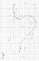
- FIG. 4 schematically shows in half section along the piston longitudinal axes 2, 102 in FIG. 1 illustrated conventional trough 104 (dashed line) together with the in FIG. 2 illustrated piston recess 4 (solid line).
Landscapes
- Engineering & Computer Science (AREA)
- Chemical & Material Sciences (AREA)
- Combustion & Propulsion (AREA)
- Mechanical Engineering (AREA)
- General Engineering & Computer Science (AREA)
- Combustion Methods Of Internal-Combustion Engines (AREA)
Priority Applications (1)
| Application Number | Priority Date | Filing Date | Title |
|---|---|---|---|
| EP07110323.8A EP2003304B1 (fr) | 2007-06-15 | 2007-06-15 | Piston doté d'une cavité pour un moteur à combustion interne et procédé destiné à la formation d'un mélange en utilisant un dispositif de vaporisation et un tel piston |
Applications Claiming Priority (1)
| Application Number | Priority Date | Filing Date | Title |
|---|---|---|---|
| EP07110323.8A EP2003304B1 (fr) | 2007-06-15 | 2007-06-15 | Piston doté d'une cavité pour un moteur à combustion interne et procédé destiné à la formation d'un mélange en utilisant un dispositif de vaporisation et un tel piston |
Publications (2)
| Publication Number | Publication Date |
|---|---|
| EP2003304A1 true EP2003304A1 (fr) | 2008-12-17 |
| EP2003304B1 EP2003304B1 (fr) | 2013-04-24 |
Family
ID=38669578
Family Applications (1)
| Application Number | Title | Priority Date | Filing Date |
|---|---|---|---|
| EP07110323.8A Ceased EP2003304B1 (fr) | 2007-06-15 | 2007-06-15 | Piston doté d'une cavité pour un moteur à combustion interne et procédé destiné à la formation d'un mélange en utilisant un dispositif de vaporisation et un tel piston |
Country Status (1)
| Country | Link |
|---|---|
| EP (1) | EP2003304B1 (fr) |
Cited By (2)
| Publication number | Priority date | Publication date | Assignee | Title |
|---|---|---|---|---|
| WO2015177897A1 (fr) * | 2014-05-22 | 2015-11-26 | 日産自動車株式会社 | Structure de chambre de combustion pour moteur diesel |
| CN115151719A (zh) * | 2020-05-19 | 2022-10-04 | 株式会社小松制作所 | 柴油发动机用的活塞以及柴油发动机 |
Citations (4)
| Publication number | Priority date | Publication date | Assignee | Title |
|---|---|---|---|---|
| JP2001227346A (ja) * | 2000-02-18 | 2001-08-24 | Honda Motor Co Ltd | 燃料直噴式ディーゼルエンジン |
| US20050066929A1 (en) * | 2003-09-29 | 2005-03-31 | Zhengbai Liu | Combustion chamber with one concave surface and three convex surfaces |
| EP1561924A2 (fr) * | 2004-02-06 | 2005-08-10 | General Motors Corporation | Moteur diesel à vitesse moyenne et grand alésage ayant la cuvette de couronne de piston avec l'angle de réentrée aigu |
| FR2878567A1 (fr) * | 2004-11-30 | 2006-06-02 | Renault Sas | Moteur diesel a injection directe et procede d'injection de combustible dans une chambre de combustion d'un tel moteur |
-
2007
- 2007-06-15 EP EP07110323.8A patent/EP2003304B1/fr not_active Ceased
Patent Citations (4)
| Publication number | Priority date | Publication date | Assignee | Title |
|---|---|---|---|---|
| JP2001227346A (ja) * | 2000-02-18 | 2001-08-24 | Honda Motor Co Ltd | 燃料直噴式ディーゼルエンジン |
| US20050066929A1 (en) * | 2003-09-29 | 2005-03-31 | Zhengbai Liu | Combustion chamber with one concave surface and three convex surfaces |
| EP1561924A2 (fr) * | 2004-02-06 | 2005-08-10 | General Motors Corporation | Moteur diesel à vitesse moyenne et grand alésage ayant la cuvette de couronne de piston avec l'angle de réentrée aigu |
| FR2878567A1 (fr) * | 2004-11-30 | 2006-06-02 | Renault Sas | Moteur diesel a injection directe et procede d'injection de combustible dans une chambre de combustion d'un tel moteur |
Cited By (4)
| Publication number | Priority date | Publication date | Assignee | Title |
|---|---|---|---|---|
| WO2015177897A1 (fr) * | 2014-05-22 | 2015-11-26 | 日産自動車株式会社 | Structure de chambre de combustion pour moteur diesel |
| CN106414943A (zh) * | 2014-05-22 | 2017-02-15 | 日产自动车株式会社 | 柴油发动机的燃烧室构造 |
| CN106414943B (zh) * | 2014-05-22 | 2019-10-18 | 日产自动车株式会社 | 柴油发动机的燃烧室构造 |
| CN115151719A (zh) * | 2020-05-19 | 2022-10-04 | 株式会社小松制作所 | 柴油发动机用的活塞以及柴油发动机 |
Also Published As
| Publication number | Publication date |
|---|---|
| EP2003304B1 (fr) | 2013-04-24 |
Similar Documents
| Publication | Publication Date | Title |
|---|---|---|
| DE69712155T2 (de) | Verbrennungskammerstruktur mit Kolbenhohlraum | |
| DE60112678T2 (de) | Direkteinspritzender ottomotor | |
| EP1592871B1 (fr) | Procede pour faire fonctionner un moteur a combustion interne avec injection directe de carburant | |
| DE60312941T2 (de) | Zündungsregler für eine fremdgezündete Brennkraftmaschine | |
| EP1537320B1 (fr) | Procedes pour faire fonctionner un moteur a combustion interne a allumage commande | |
| EP1409863B1 (fr) | Procede servant a augmenter la temperature d'echappement d'un moteur a combustion interne a injection directe et allumage commande | |
| DE69717050T2 (de) | Brennkammer | |
| DE102010017575B4 (de) | Verfahren zum Betreiben einer fremdgezündeten Brennkraftmaschine und Brennkraftmaschine zur Durchführung eines derartigen Verfahrens | |
| WO2005033496A1 (fr) | Procede de fonctionnement d'un moteur a combustion interne | |
| WO2007031157A1 (fr) | Procede pour faire fonctionner un moteur a combustion a allumage commande | |
| EP2003303B1 (fr) | Piston doté d'une cavité pour un moteur à combustion interne et procédé destiné à la formation d'un mélange en utilisant un dispositif de vaporisation et un tel piston | |
| DE102005044544B4 (de) | Verfahren zum Betrieb einer fremdgezündeten 4-Takt-Brennkraftmaschine | |
| DE102004017988B4 (de) | Verfahren zum Betrieb einer Brennkraftmaschine mit Kraftstoffdirekteinspritzung | |
| EP1363010A2 (fr) | Procédé pour faire fonctionner un moteur à allumage commandé avec injection multiple | |
| DE102016212951A1 (de) | Direkteinspritzende fremdgezündete Brennkraftmaschine mit im Zylinderrohr angeordneter Einspritzvorrichtung und Verfahren zum Betreiben einer derartigen Brennkraftmaschine | |
| EP2003304B1 (fr) | Piston doté d'une cavité pour un moteur à combustion interne et procédé destiné à la formation d'un mélange en utilisant un dispositif de vaporisation et un tel piston | |
| EP1703112A1 (fr) | Procédé de chauffage d'un catalyseur d'un moteur à combustion interne | |
| EP1630380B1 (fr) | Méthode d'injection de carburant dans la chambre de combustion d'un moteur à combustion interne avec en injecteur et en piston pour la mise en oeuvre de ce procédé | |
| WO2016012068A1 (fr) | Procédé de combustion | |
| EP1007828A1 (fr) | Moteur a combustion interne et procede d'allumage et de combustion d'un moteur a combustion interne | |
| DE102005051740A1 (de) | Brennraum einer selbstzündenden Brennkraftmaschine | |
| DE102005055367A1 (de) | Dieselbrennkraftmaschine | |
| DE19714796A1 (de) | Verfahren und Vorrichtung zur Entflammung sehr magerer Kraftstoff-Luft-Gemische bei Ottomotoren | |
| EP1491740B1 (fr) | Procédé de fonctionnement d'un moteur Diesel | |
| EP1630386A1 (fr) | Méthode de fonctionnement d'un moteur à combustion interne hybride pouvant fonctionner à la fois en mode HCCI ou SI, et moteur à combustion interne pour mettre en oeuvre ce procédé |
Legal Events
| Date | Code | Title | Description |
|---|---|---|---|
| PUAI | Public reference made under article 153(3) epc to a published international application that has entered the european phase |
Free format text: ORIGINAL CODE: 0009012 |
|
| AK | Designated contracting states |
Kind code of ref document: A1 Designated state(s): AT BE BG CH CY CZ DE DK EE ES FI FR GB GR HU IE IS IT LI LT LU LV MC MT NL PL PT RO SE SI SK TR |
|
| AX | Request for extension of the european patent |
Extension state: AL BA HR MK RS |
|
| 17P | Request for examination filed |
Effective date: 20090617 |
|
| AKX | Designation fees paid |
Designated state(s): DE FR GB |
|
| GRAP | Despatch of communication of intention to grant a patent |
Free format text: ORIGINAL CODE: EPIDOSNIGR1 |
|
| GRAS | Grant fee paid |
Free format text: ORIGINAL CODE: EPIDOSNIGR3 |
|
| GRAA | (expected) grant |
Free format text: ORIGINAL CODE: 0009210 |
|
| AK | Designated contracting states |
Kind code of ref document: B1 Designated state(s): DE FR GB |
|
| REG | Reference to a national code |
Ref country code: GB Ref legal event code: FG4D Free format text: NOT ENGLISH |
|
| REG | Reference to a national code |
Ref country code: DE Ref legal event code: R096 Ref document number: 502007011648 Country of ref document: DE Effective date: 20130620 |
|
| PLBI | Opposition filed |
Free format text: ORIGINAL CODE: 0009260 |
|
| 26 | Opposition filed |
Opponent name: DEUTZ AG Effective date: 20140121 |
|
| PLAX | Notice of opposition and request to file observation + time limit sent |
Free format text: ORIGINAL CODE: EPIDOSNOBS2 |
|
| REG | Reference to a national code |
Ref country code: DE Ref legal event code: R026 Ref document number: 502007011648 Country of ref document: DE Effective date: 20140121 |
|
| PLBB | Reply of patent proprietor to notice(s) of opposition received |
Free format text: ORIGINAL CODE: EPIDOSNOBS3 |
|
| APBM | Appeal reference recorded |
Free format text: ORIGINAL CODE: EPIDOSNREFNO |
|
| APBP | Date of receipt of notice of appeal recorded |
Free format text: ORIGINAL CODE: EPIDOSNNOA2O |
|
| APAH | Appeal reference modified |
Free format text: ORIGINAL CODE: EPIDOSCREFNO |
|
| APBQ | Date of receipt of statement of grounds of appeal recorded |
Free format text: ORIGINAL CODE: EPIDOSNNOA3O |
|
| APBM | Appeal reference recorded |
Free format text: ORIGINAL CODE: EPIDOSNREFNO |
|
| APBP | Date of receipt of notice of appeal recorded |
Free format text: ORIGINAL CODE: EPIDOSNNOA2O |
|
| REG | Reference to a national code |
Ref country code: FR Ref legal event code: PLFP Year of fee payment: 10 |
|
| APAW | Appeal reference deleted |
Free format text: ORIGINAL CODE: EPIDOSDREFNO |
|
| APAY | Date of receipt of notice of appeal deleted |
Free format text: ORIGINAL CODE: EPIDOSDNOA2O |
|
| APBM | Appeal reference recorded |
Free format text: ORIGINAL CODE: EPIDOSNREFNO |
|
| APBP | Date of receipt of notice of appeal recorded |
Free format text: ORIGINAL CODE: EPIDOSNNOA2O |
|
| REG | Reference to a national code |
Ref country code: FR Ref legal event code: PLFP Year of fee payment: 11 |
|
| REG | Reference to a national code |
Ref country code: FR Ref legal event code: PLFP Year of fee payment: 12 |
|
| APBU | Appeal procedure closed |
Free format text: ORIGINAL CODE: EPIDOSNNOA9O |
|
| PLCK | Communication despatched that opposition was rejected |
Free format text: ORIGINAL CODE: EPIDOSNREJ1 |
|
| STAA | Information on the status of an ep patent application or granted ep patent |
Free format text: STATUS: THE PATENT HAS BEEN GRANTED |
|
| REG | Reference to a national code |
Ref country code: DE Ref legal event code: R100 Ref document number: 502007011648 Country of ref document: DE |
|
| PLBN | Opposition rejected |
Free format text: ORIGINAL CODE: 0009273 |
|
| STAA | Information on the status of an ep patent application or granted ep patent |
Free format text: STATUS: OPPOSITION REJECTED |
|
| 27O | Opposition rejected |
Effective date: 20181014 |
|
| PGFP | Annual fee paid to national office [announced via postgrant information from national office to epo] |
Ref country code: FR Payment date: 20190522 Year of fee payment: 13 |
|
| PGFP | Annual fee paid to national office [announced via postgrant information from national office to epo] |
Ref country code: GB Payment date: 20190524 Year of fee payment: 13 |
|
| PGFP | Annual fee paid to national office [announced via postgrant information from national office to epo] |
Ref country code: DE Payment date: 20200518 Year of fee payment: 14 |
|
| GBPC | Gb: european patent ceased through non-payment of renewal fee |
Effective date: 20200615 |
|
| PG25 | Lapsed in a contracting state [announced via postgrant information from national office to epo] |
Ref country code: GB Free format text: LAPSE BECAUSE OF NON-PAYMENT OF DUE FEES Effective date: 20200615 Ref country code: FR Free format text: LAPSE BECAUSE OF NON-PAYMENT OF DUE FEES Effective date: 20200630 |
|
| REG | Reference to a national code |
Ref country code: DE Ref legal event code: R119 Ref document number: 502007011648 Country of ref document: DE |
|
| PG25 | Lapsed in a contracting state [announced via postgrant information from national office to epo] |
Ref country code: DE Free format text: LAPSE BECAUSE OF NON-PAYMENT OF DUE FEES Effective date: 20220101 |