EP2003368A2 - Dispositif d'engrenage du type à engrènement flexible et dispositif de direction pour véhicule - Google Patents
Dispositif d'engrenage du type à engrènement flexible et dispositif de direction pour véhicule Download PDFInfo
- Publication number
- EP2003368A2 EP2003368A2 EP07739881A EP07739881A EP2003368A2 EP 2003368 A2 EP2003368 A2 EP 2003368A2 EP 07739881 A EP07739881 A EP 07739881A EP 07739881 A EP07739881 A EP 07739881A EP 2003368 A2 EP2003368 A2 EP 2003368A2
- Authority
- EP
- European Patent Office
- Prior art keywords
- gear
- tooth
- internal gear
- flexible
- meshing
- Prior art date
- Legal status (The legal status is an assumption and is not a legal conclusion. Google has not performed a legal analysis and makes no representation as to the accuracy of the status listed.)
- Withdrawn
Links
- 230000005540 biological transmission Effects 0.000 description 26
- 230000003247 decreasing effect Effects 0.000 description 9
- 230000004048 modification Effects 0.000 description 7
- 238000012986 modification Methods 0.000 description 7
- 238000010586 diagram Methods 0.000 description 3
- 238000004519 manufacturing process Methods 0.000 description 2
- 238000005452 bending Methods 0.000 description 1
- 230000008602 contraction Effects 0.000 description 1
- 230000005489 elastic deformation Effects 0.000 description 1
- 230000009466 transformation Effects 0.000 description 1
Images


Classifications
-
- F—MECHANICAL ENGINEERING; LIGHTING; HEATING; WEAPONS; BLASTING
- F16—ENGINEERING ELEMENTS AND UNITS; GENERAL MEASURES FOR PRODUCING AND MAINTAINING EFFECTIVE FUNCTIONING OF MACHINES OR INSTALLATIONS; THERMAL INSULATION IN GENERAL
- F16H—GEARING
- F16H55/00—Elements with teeth or friction surfaces for conveying motion; Worms, pulleys or sheaves for gearing mechanisms
- F16H55/02—Toothed members; Worms
- F16H55/08—Profiling
- F16H55/0833—Flexible toothed member, e.g. harmonic drive
-
- B—PERFORMING OPERATIONS; TRANSPORTING
- B62—LAND VEHICLES FOR TRAVELLING OTHERWISE THAN ON RAILS
- B62D—MOTOR VEHICLES; TRAILERS
- B62D5/00—Power-assisted or power-driven steering
- B62D5/008—Changing the transfer ratio between the steering wheel and the steering gear by variable supply of energy, e.g. by using a superposition gear
-
- Y—GENERAL TAGGING OF NEW TECHNOLOGICAL DEVELOPMENTS; GENERAL TAGGING OF CROSS-SECTIONAL TECHNOLOGIES SPANNING OVER SEVERAL SECTIONS OF THE IPC; TECHNICAL SUBJECTS COVERED BY FORMER USPC CROSS-REFERENCE ART COLLECTIONS [XRACs] AND DIGESTS
- Y10—TECHNICAL SUBJECTS COVERED BY FORMER USPC
- Y10T—TECHNICAL SUBJECTS COVERED BY FORMER US CLASSIFICATION
- Y10T74/00—Machine element or mechanism
- Y10T74/19—Gearing
- Y10T74/19949—Teeth
- Y10T74/19963—Spur
- Y10T74/19967—Yieldable
Definitions
- the present invention relates to a flexible meshing-type gear device including a fixed internal gear, a movable internal gear, a flexible external gear meshing with these internal gears, and a wave generator supporting the flexible external gear from the inner circumference thereof so as to allow a relative rotation, and also relates to a steering device for a vehicle including the flexible meshing-type gear device.
- the flexible meshing-type gear device 16 is provided with an annular fixed internal gear 20 (illustrated in Fig. 2 ) fixed and supported on a housing (not illustrated) and an annular movable internal gear 21 adjacent to the fixed internal gear 20, and a flexible external gear 22 capable of meshing with these internal gears 20 and 21 is arranged inside the fixed internal gear 20 and the movable internal gear 21.
- the flexible external gear 22 is supported by a wave generator 23 arranged thereinside so as to mesh with the fixed internal gear 20 and the movable internal gear 21.
- a flexible external gear 60 rotates relative to a fixed internal gear 63. Therefore, one tooth top edge 62 of an external tooth 61 of the flexible external gear 60 moves on a locus 65 indicated by the broken line crossing over an internal tooth 64 with respect to the internal tooth 64 of the fixed internal gear 63.
- each external tooth 61 of the flexible external gear 60 repeats a movement by which the tooth top edge 62 is brought into contact with a part of the tooth surface of the internal tooth 64 of the fixed internal gear 63 substantially at one point.
- tooth forms of the respective tooth end surfaces of the fixed internal gear, the movable internal gear and the external gear are formed based on movement locus due to rack approximation of an external tooth with respect to each internal tooth and also formed by a map curve due to similarity transformation based on a 1/2 contraction ratio, with a limit position at which each internal tooth is in contact with an external tooth given as an original point.
- the tooth surface of an external tooth of the external gear is to be continuously in contact with the tooth surface of each internal tooth of the internal gear. Therefore, according to this constitution, the angular transmission error is decreased.
- each external tooth of the flexible external gear oscillates in association with the rotation of the wave generator.
- the flexible external gear 70 meshes respectively with the fixed internal gear 72 and the movable internal gear 73 by an external tooth 71 facing the direction of the Y axis.
- the orientation of the external tooth 71 is Y0 at which the external tooth 71 rotates counterclockwise from the direction of the Y axis.
- each external tooth of the flexible external gear 70 oscillates with respect to each internal tooth of the fixed internal gear 72 and that of the movable internal gear 73 in association with the rotation of the wave generator.
- the movement locus of an external tooth with respect to each internal tooth is determined based on the rack approximation.
- the movement locus is free of an oscillating movement component of an external tooth with respect to each internal tooth. Therefore, the difference between the movement locus and an actual movement locus of an external tooth of the flexible external gear is increased accordingly as the fixed internal gear, the movable internal gear and the flexible external gear become smaller in the number of teeth.
- An objective of the present invention is to provide a flexible meshing-type gear device with a reduced angular transmission error and a steering device for a vehicle including the flexible meshing-type gear device.
- a flexible meshing-type gear device includes a fixed internal gear; a movable internal gear different in the number of teeth from the fixed internal gear and movable coaxially with the fixed internal gear; an annular flexible external gear capable of meshing respectively with the fixed internal gear and the movable internal gear; and a wave generator which supports the flexible external gear to allow a relative rotation inside the flexible external gear so as to mesh with the fixed internal gear and the movable internal gear, thereby allowing a position at which the flexible external gear meshes with the fixed internal gear and the movable internal gear to move in a rotational direction.
- a meshing surface is formed that conforms to a locus in which the tooth top edge of each external tooth of the flexible external gear moves based on the rotation of the wave generator.
- the flexible meshing-type gear device of the first aspect of the present invention when rotation is input to the wave generator from outside, the flexible external gear is driven flexibly by the wave generator. Next, the position at which each external tooth of the flexible external gear meshes with each internal tooth of the fixed internal gear and that of the movable internal gear is moved sequentially, thereby the movable internal gear is rotated and driven. As a result, the rotation input to the wave generator from outside is reduced and output externally from the movable internal gear. Further, a meshing surface in conformity with a locus on which the tooth top edge of each external tooth of the flexible external gear moves based on the rotation of the wave generator is formed on the tooth surfaces of the respective internal teeth of the fixed internal gear and the movable internal gear.
- the meshing surface is caused to retreat in a direction in which the fixed internal gear and the movable internal gear are moved and rotated around the central axis, thereby providing a backlash.
- the meshing surface is caused to retreat so that the retreat amount increases from the tooth root of the internal tooth toward the tooth top.
- the tooth top edge is formed in a circular arc shape.
- a relief angle ⁇ of the flexible external gear is set so that the following formula ⁇ + ⁇ ⁇ ⁇ is met based on a tangent angle ⁇ at any given point on the meshing surface and an oscillating angle ⁇ of the external tooth of the flexible external gear.
- a steering device for a vehicle is a steering device for a vehicle in which rotation of a steering shaft is transmitted to a pinion shaft, and the rotational output of an electric motor is also transmitted to the pinion shaft via a reduction gear, such that the rotational ratio of the pinion shaft with respect to the steering shaft can be adjusted.
- the steering device is provided with the flexible meshing-type gear device described in any one of claim 1 to claim 7 as the reduction gear.
- the above constitution is assembled into the steering device, thereby reducing an angular transmission error between the rotational output of an auxiliary electric motor and the rotation of the pinion shaft via the flexible meshing-type gear device based on the rotational output. Therefore, it is possible to improve the accuracy of steering control of a steering wheel based on the control of the electric motor and also improve the steering feel due to a decrease in vibration and noise.
- Fig. 3 shows a steering device 1 which is mounted on a vehicle.
- the steering device 1 is provided with a universal joint 11 to which a steering shaft 10 is connected, a pinion shaft 12 connected to a steering gear box (not illustrated), and a variable transmission ratio device 13 which connects the universal joint 11 with the pinion shaft 12.
- the variable transmission ratio device 13 is provided with a housing 14 coupled to the universal joint 11 and also provided, inside the housing 14, with a DC motor (electric motor) 15 arranged coaxially with the pinion shaft 12, and a flexible meshing-type gear device 17 which outputs the rotation input from an output shaft 19 of the DC motor 15 to the pinion shaft 12.
- the above-constituted steering device 1 transmits the rotation of the steering shaft 10 to the pinion shaft and also transmits the rotational output of the DC motor 15 to the pinion shaft via the flexible meshing-type gear device 17, thereby adjusting the rotational ratio of the pinion shaft 12 to the steering shaft 10.
- the flexible meshing-type gear device 17 is provided with an annular fixed internal gear 20 (illustrated only in Fig. 2 ) which is fixed and supported on the housing 14.
- the number of teeth of the fixed internal gear 20 is set to be 102, for example.
- a movable internal gear 21 smaller in the number of teeth than the fixed internal gear 20 is supported on the pinion shaft 12 of the fixed internal gear 20 so as to be rotatable with respect to the housing 14 coaxially with the fixed internal gear 20.
- the number of teeth of the movable internal gear 21 is set to be 100, for example.
- annular flexible external gear 22 which has the same number of teeth as the movable internal gear 21 and meshes respectively with the fixed internal gear 20 and the movable internal gear 21.
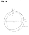
- an elliptical wave generator 23 which supports the flexible external gear 22 from the inner circumference so as to allow a relative rotation and allows the flexible external gear 22 to mesh with the fixed internal gear 20 and the movable internal gear 21 respectively at two opposing positions.
- the wave generator 23 is rotated based on the rotational input from the output shaft 19 of the DC motor 15, thereby changing a position at which the flexible external gear 22 meshes with the fixed internal gear 20 and the movable internal gear 21.
- the movable internal gear 21 moves rotationally only by the difference in the number of teeth of the fixed internal gear 20 per rotation of the wave generator 23.
- variable transmission ratio device 13 is controlled for a rotational angle of the DC motor 15, for example, based on the turning angle of a steering wheel and the speed of a vehicle. Thereby, the tire angle of the front wheel is controlled depending on the turning angle of the steering wheel and the speed of the vehicle.
- the DC motor is rotated positively or reversely, by which the pinion shaft 12 is increased or decreased in speed according to the rotational input of the DC motor 15. Thereby, it is possible to adjust the steering feel depending on the traveling speed or the like of a vehicle.
- each external tooth of the flexible external gear 22 is of an involute tooth form having a pressure angle of 18 degrees, for example.
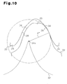
- the tooth top edge 26 of the external tooth 25 is formed in a straight configuration. Nonetheless, as shown in Figs. 8 and 9 , the tooth top edge 26 may be formed in a circular arc shape.
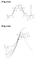
- FIGs. 4(a), 4(b) , and 5 show a state where one external tooth 25 of the flexible external gear 22 meshes with one internal tooth 24 of the fixed internal gear 20 in association with the rotation of the wave generator 23.
- a meshing surface 28 (indicated by the thick line) conforming to the locus 27 is formed.
- a relief configuration indicated by a cubic curve is formed on both sides of the meshing surface 28 in the vertical direction shown in Fig. 4(b) .
- the meshing surface 28 is formed on both sides of each internal tooth 24 so as to correspond to a case where the wave generator 23 is rotated in both directions. Next, the meshing surface 28 is formed in a range from 1/6 to 4/6 with respect to the height ⁇ 1 of the internal tooth 24.
- the tooth top edge 26 of the external tooth 25 moves on the locus 27 indicated by the broken line with respect to each internal tooth 24 of the fixed internal gear 20 as shown in Figs. 4(b) and 5 , in association with the rotation of the wave generator 23.
- the tooth top edge 26 of the external tooth 25 is continuously in slidable contact with the meshing surface 28 of each internal tooth 24 of the fixed internal gear 20.
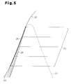
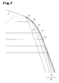
- FIGs. 6(a), 6(b) and 7 show a state where one external tooth 25 of the flexible external gear 22 meshes with one internal tooth 29 of the movable internal gear 21 in association with the rotation of the wave generator 23.
- a meshing surface 31 (indicated by the thick line) conforming to the locus 30 is formed.
- a relief configuration indicated by a cubic curve is formed on both sides of the meshing surface 31 in the vertical direction shown in Fig. 6(b) .
- the meshing surface 31 is formed on both sides of each internal tooth 29 so as to correspond to a case where the wave generator 23 is rotated in both directions. Next, the meshing surface 31 is formed in a range from 1/6 to 4/6 with respect to the height ⁇ 2 of the internal tooth 29.
- the tooth top edge 26 of the external tooth 25 moves on the oblong locus 30 indicated by the broken line with respect to each internal tooth 29 of the movable internal gear 21 as shown in Figs. 6(b) and 7 , in association with the wave generator 23.
- the tooth top edge 26 of the external tooth 25 is in slidable contact with the meshing surface 31 of the corresponding internal tooth 29 of the movable internal gear 21.
- each external tooth 25 of the flexible external gear 22 is continuously in contact with the meshing surfaces 28 and 31 of the respective internal teeth 24 and 29 of the fixed internal gear 20 and the movable internal gear 21. Therefore, an angular transmission error is decreased between the wave generator 23 and the movable internal gear 21.
- a tooth form of the internal tooth 24 of the fixed internal gear 20 and that of the internal tooth 29 of the movable internal gear 21 are set as follows based on the circular arc of the tooth top edge 26 of the external tooth 25 of the flexible external gear 22.
- the loci 27 and 30 spaced externally away only by a radius ⁇ of the circular arc of the tooth top edge 26 are determined respectively from the loci 32 and 33 on which the circular arc center point 26 ⁇ of the tooth top edge 26 of the external tooth 25 moves based on the rotation of the wave generator 23.
- ⁇ is an oscillating angle of the external tooth 25 of the flexible external gear 22, and ⁇ is a tangent angle at any position of the meshing surfaces 28 and 31.
- the tooth top edge 26 of the external tooth 25 is allowed to be continuously in slidable contact with the respective internal teeth 24 and 29 of the fixed internal gear 20 and the movable internal gear 21, while avoiding their mutual interference.
- the meshing surfaces 28 and 31 conforming partially to the loci 27 and 30 on which the tooth top edge 26 of each external tooth 25 of the flexible external gear 22 moves are respectively formed.
- each external tooth 25 of the flexible external gear 22 is continuously in slidable contact with the respective internal teeth 24 and 29 of the fixed internal gear 20 and the movable internal gear 21, an angular transmission error between the wave generator 23 and the movable internal gear 21 is decreased to suppress vibration and noise.
- a circular arc portion 34 corresponding to the tooth top edge 26 of the external tooth 25 shown in Figs. 4 to 9 is formed at the tooth surface distal end portion of the external tooth 25.
- the circular arc portion 34 is formed with a great radius to improve the wear resistance of the external tooth 25.
- the circular arc portion 34 is formed on a circular arc having a radius ⁇ ' of 1/2 or greater of the tooth width of the external tooth 25.
- a center point 34 ⁇ of the circular arc draws the loci 32 and 33 in association with the rotation of the flexible external gear 22.
- the tooth top of the external tooth 25 is cut so as not to interfere with the tooth root of the internal tooth 24 of the fixed internal gear 20 or the tooth root of the internal tooth 29 of the movable internal gear 21. It is noted that the circular arc portion 34 may also be formed in a circular arc having a radius greater than the tooth width of the external tooth 25.
- FIG. 12 An explanation will be made of a second embodiment of the present invention with reference to Figs. 12 and 13 .
- the present embodiment is different in that the internal teeth 24 and 29 of the internal gears 20 and 21 in the first embodiment are changed in configuration.
- both tooth surfaces of the internal tooth 29 of the movable internal gear 21 are formed, as with the tooth surface 24 ⁇ of the internal tooth 24, in such a configuration that the meshing surface 31 is allowed to move rotationally about the center of the central position of the tooth root between both adjacent internal teeth 29 with respect to the meshing surface 31.
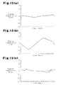
- a tooth form error exists in the external tooth 25 of the flexible external gear 22 and in the respective internal teeth 24 and 29 of the fixed internal gear 20 and the movable internal gear 21. It is, for example, assumed that an actual tooth surface 24 ⁇ of the internal tooth 24 of the fixed internal gear 20 is caused to retreat so that the retreat amount is gradually increased from the tooth top of the internal tooth 24 toward the tooth root with respect to the meshing surface 28. In this instance, an angular transmission error between an ideal output angle from the movable internal gear 21 with respect to an input angle to the flexible external gear 22, and an actual output angle is increased with respect to an angular transmission error in a case where the tooth surface 24 ⁇ of the internal tooth 24 is in conformity with the meshing surface 31.
- the angular transmission error changes with respect to an input angle to the flexible external gear 22, as shown in Fig. 13(a) .
- the angular transmission error is increased over the entire range of the input angle to the flexible external gear 22 as shown in Fig. 13(b) .
- the angular transmission error is obtained through calculations.
- the angular transmission error is decreased in the entire range of the input angle as shown in Fig. 13(c) .
- the meshing surface 31 of the movable internal gear 21 is deformed as described above. The angular transmission error in the output angle from the movable internal gear 21 in relation to the input angle into the flexible external gear 22 is prevented from increasing.
- the actual tooth surfaces 24 ⁇ of the internal teeth 24 and 29 are caused to retreat so that the retreat amount is gradually increased from the tooth root toward the tooth top with respect to the meshing surface 28. Therefore, even if there is a tooth form error in the respective internal teeth 24 and 29 of the fixed internal gear 20 and the movable internal gear 21, an increase in the angular transmission error is suppressed.
- the flexible meshing-type gear device 17 is free from any increase in angular transmission error, thereby making it possible to improve the productivity by decreasing the accuracy of manufacturing the fixed internal gear 20 and the movable internal gear 21.
- a third embodiment according to the present invention is different in that a configuration of the external tooth 25 of the flexible external gear 22 in the modification of the first embodiment shown in Figs. 10 and 11 is changed.
- a pressure angle of the tooth surface region 35 leading to an end portion 34 ⁇ of the tooth root of the circular arc portion 34 on the external tooth 25 of the flexible external gear 22 is set to be equal to a pressure angle of the end portion 34 ⁇ of the circular arc portion 34, in other words, a minimum pressure angle (20 degrees, for example) at the circular arc portion 34.
- the height ⁇ 3 of the tooth surface region 35 is set in a range from 1/6 to 1/3 of a tooth height ⁇ 4 of the external tooth 25.
- a pressure angle of the tooth surface region 35 leading to the end portion 34 ⁇ of the tooth root at the circular arc portion 34 of the external tooth 25 is set to be the minimum pressure angle, as with the end portion 34 ⁇ of the circular arc portion 34.
- the pressure angle of the tooth surface region 35 leading to the end portion 34 ⁇ on the tooth root of the circular arc portion 34 in the external tooth 25 of the flexible external gear 22 is set to be equal to the pressure angle of the end portion 34 ⁇ . Therefore, ratcheting is suppressed from occurring between the flexible external gear 22 and the fixed and movable internal gears 20, 21, so that an angular transmission deviation in the flexible meshing-type gear device 17 is suppressed from occurring.
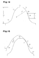
- FIG. 16 An explanation will be made of a fourth embodiment of the present invention with reference to Fig. 16 .
- the present embodiment is different in that the configurations of the internal teeth 24 and 29 of the internal gears 20 and 21 in the first embodiment are changed.
- the meshing surface 28 of the internal tooth 24 is caused to retreat by approximately 6° to 9° in a direction in which the fixed internal gear 20 is moved and rotated around the central axis with respect to an ideal tooth form, thereby providing a backlash.
- tooth forms constituting the meshing surfaces 28 and 31 are moved in a direction in which the flexible external gear 22 is rotated. Therefore, unlike a case where the meshing surfaces 28 and 31 are moved radially to form a backlash, a pitch circle or the like is prevented from being changed, thus making it possible to obtain a smooth meshing by suppressing an angular transmission error.
- the meshing surfaces 28 and 31 of the internal teeth 24 and 29 are caused to retreat in a direction in which the fixed internal gear 20 and the movable internal gear 21 are moved and rotated around the central axis, thereby forming a backlash.
- a pitch extension or the like is prevented from being changed, thereby suppressing an angular transmission error and allowing the flexible external gear 22 to smoothly mesh with the fixed internal gear 20 and the movable internal gear 21.
- the present invention is not restricted to the above embodiments, and the fixed internal gear 20 may be equal in the number of teeth to the flexible external gear 22, and the movable internal gear 21 may be different in the number of teeth from the flexible external gear 22.
- the tooth top edge 26 of the external tooth 25 of the flexible external gear 22 is in slidable contact with the meshing surface 28 of the corresponding internal tooth 24 of the fixed internal gear 20 and also sequentially in slidable contact with the meshing surface 31 of each internal tooth 29 of the movable internal gear 21.
- the fixed internal gear 20, the movable internal gear 21 and the flexible external gear 22 may be different from each other in the number of teeth.
- the tooth top edge 26 of the external tooth 25 of flexible external gear 22 is sequentially in slidable contact with the meshing surface 28 of the internal tooth 24 of the fixed internal gear 20 and also sequentially in slidable contact with the meshing surface 31 of each internal tooth 29 of the movable internal gear 21.
- the wave generator 23 may be formed in an eccentric circle or in a polygonal configuration such as a substantially triangular shape, a substantially rectangular shape or a substantially pentagonal shape, and the flexible external gear 22 may mesh with the fixed internal gear 20 and the movable internal gear 21 respectively at a single point, three points, four points, five points or the like.
Landscapes
- Engineering & Computer Science (AREA)
- Mechanical Engineering (AREA)
- General Engineering & Computer Science (AREA)
- Chemical & Material Sciences (AREA)
- Combustion & Propulsion (AREA)
- Transportation (AREA)
- Retarders (AREA)
Applications Claiming Priority (2)
| Application Number | Priority Date | Filing Date | Title |
|---|---|---|---|
| JP2006097828 | 2006-03-31 | ||
| PCT/JP2007/056443 WO2007116756A1 (fr) | 2006-03-31 | 2007-03-27 | Dispositif d'engrenage du type à engrènement flexible et dispositif de direction pour véhicule |
Publications (2)
| Publication Number | Publication Date |
|---|---|
| EP2003368A2 true EP2003368A2 (fr) | 2008-12-17 |
| EP2003368A9 EP2003368A9 (fr) | 2009-04-22 |
Family
ID=38581053
Family Applications (1)
| Application Number | Title | Priority Date | Filing Date |
|---|---|---|---|
| EP07739881A Withdrawn EP2003368A2 (fr) | 2006-03-31 | 2007-03-27 | Dispositif d'engrenage du type à engrènement flexible et dispositif de direction pour véhicule |
Country Status (4)
| Country | Link |
|---|---|
| US (1) | US20090044651A1 (fr) |
| EP (1) | EP2003368A2 (fr) |
| JP (1) | JPWO2007116756A1 (fr) |
| WO (1) | WO2007116756A1 (fr) |
Cited By (6)
| Publication number | Priority date | Publication date | Assignee | Title |
|---|---|---|---|---|
| EP2674642A1 (fr) * | 2012-06-14 | 2013-12-18 | Harmonic Innovation Technology Co., Ltd. | Harmonic drive avec pignon stationnaire |
| WO2015086841A1 (fr) * | 2013-12-13 | 2015-06-18 | Ovalo Gmbh | Direction de véhicule pourvue d'un actionneur de superposition |
| LU92750B1 (de) * | 2015-06-12 | 2016-12-13 | Ovalo Gmbh | Radial bauraumsparendes spannungswellengetriebe |
| WO2016198673A1 (fr) * | 2015-06-12 | 2016-12-15 | Ovalo Gmbh | Engrenage à onde de déformation à faible encombrement radial |
| EP3173658A4 (fr) * | 2014-07-23 | 2018-05-02 | Harmonic Drive Systems Inc. | Dispositif d'engrenage à onde de type double |
| DE102008060427B4 (de) * | 2007-12-04 | 2021-02-11 | Harmonic Drive Systems Inc. | Verfahren zum Bestimmen eines Zahnprofils |
Families Citing this family (12)
| Publication number | Priority date | Publication date | Assignee | Title |
|---|---|---|---|---|
| JP5227853B2 (ja) * | 2009-03-09 | 2013-07-03 | 株式会社ジェイテクト | 揺動型歯車装置、伝達比可変機構、および車両用操舵装置 |
| US8475315B2 (en) * | 2010-02-15 | 2013-07-02 | Jtekt Corporation | Swing internal contact type planetary gear device and rotation drive device |
| CN103270335B (zh) * | 2011-01-26 | 2015-12-09 | 住友重机械工业株式会社 | 挠曲啮合式齿轮装置及挠曲啮合式齿轮装置的齿形确定方法 |
| TWI425155B (zh) * | 2011-01-26 | 2014-02-01 | Sumitomo Heavy Industries | The method of determining the tooth shape of flexible bite gear device and flexible bite gear device |
| DE112012005619T5 (de) * | 2012-01-10 | 2014-10-09 | Harmonic Drive Systems Inc. | Verformungswellgetriebe mit einem Involutenzahnprofil mit positiver Biegung, das die Randdicke berücksichtigt |
| WO2017122362A1 (fr) * | 2016-01-15 | 2017-07-20 | 株式会社ハーモニック・ドライブ・システムズ | Dispositif d'engrenage à onde de déformation avec séparation pure de deux contraintes |
| JP6830736B2 (ja) * | 2017-06-05 | 2021-02-17 | 株式会社ハーモニック・ドライブ・システムズ | 2応力純分離の波動歯車装置 |
| US11578789B2 (en) | 2018-11-07 | 2023-02-14 | Delta Electronics, Inc. | Cycloid speed reducer |
| US11336147B2 (en) * | 2018-11-07 | 2022-05-17 | Delta Electronics, Inc. | Speed reducing device having power source |
| KR102146753B1 (ko) * | 2019-09-03 | 2020-08-21 | 숭실대학교산학협력단 | 물림률이 향상된 하모닉 드라이브 기어 |
| US11732791B2 (en) * | 2020-01-08 | 2023-08-22 | Harmonic Drive System Inc. | Strain wave gearing |
| CN114263708B (zh) * | 2021-12-31 | 2024-02-06 | 浙江如川谐波传动科技有限公司 | 一种谐波减速器 |
Family Cites Families (7)
| Publication number | Priority date | Publication date | Assignee | Title |
|---|---|---|---|---|
| JPS6045959U (ja) * | 1983-09-06 | 1985-04-01 | 株式会社 ハ−モニツク・ドライブ・システムズ | 調和歯車装置 |
| JPS62141358A (ja) * | 1985-12-17 | 1987-06-24 | Sumitomo Heavy Ind Ltd | 噛合機構における歯形 |
| JPH0784896B2 (ja) | 1986-11-05 | 1995-09-13 | 株式会社ハーモニック・ドライブ・システムズ | 撓み噛み合い式歯車装置 |
| JP2503027B2 (ja) * | 1987-09-21 | 1996-06-05 | 株式会社ハーモニック・ドライブ・システムズ | 撓みかみ合い式歯車装置 |
| JP2612591B2 (ja) * | 1988-05-18 | 1997-05-21 | 株式会社ハーモニック・ドライブ・システムズ | たわみ噛み合い式歯車装置 |
| JP3739017B2 (ja) * | 1995-12-15 | 2006-01-25 | 株式会社ハーモニック・ドライブ・システムズ | 非干渉広域かみ合い歯形を有する撓みかみ合い式歯車装置 |
| JP4626211B2 (ja) * | 2004-07-30 | 2011-02-02 | 株式会社ジェイテクト | 波動歯車装置、伝達比可変装置、及び波動歯車装置の製造方法 |
-
2007
- 2007-03-27 US US12/295,319 patent/US20090044651A1/en not_active Abandoned
- 2007-03-27 JP JP2008509783A patent/JPWO2007116756A1/ja active Pending
- 2007-03-27 WO PCT/JP2007/056443 patent/WO2007116756A1/fr not_active Ceased
- 2007-03-27 EP EP07739881A patent/EP2003368A2/fr not_active Withdrawn
Non-Patent Citations (1)
| Title |
|---|
| See references of WO2007116756A1 * |
Cited By (8)
| Publication number | Priority date | Publication date | Assignee | Title |
|---|---|---|---|---|
| DE102008060427B4 (de) * | 2007-12-04 | 2021-02-11 | Harmonic Drive Systems Inc. | Verfahren zum Bestimmen eines Zahnprofils |
| EP2674642A1 (fr) * | 2012-06-14 | 2013-12-18 | Harmonic Innovation Technology Co., Ltd. | Harmonic drive avec pignon stationnaire |
| WO2015086841A1 (fr) * | 2013-12-13 | 2015-06-18 | Ovalo Gmbh | Direction de véhicule pourvue d'un actionneur de superposition |
| EP3079967B1 (fr) | 2013-12-13 | 2019-10-09 | Ovalo GmbH | Direction de véhicule pourvue d'un actionneur de superposition |
| EP3173658A4 (fr) * | 2014-07-23 | 2018-05-02 | Harmonic Drive Systems Inc. | Dispositif d'engrenage à onde de type double |
| LU92750B1 (de) * | 2015-06-12 | 2016-12-13 | Ovalo Gmbh | Radial bauraumsparendes spannungswellengetriebe |
| WO2016198673A1 (fr) * | 2015-06-12 | 2016-12-15 | Ovalo Gmbh | Engrenage à onde de déformation à faible encombrement radial |
| US10927938B2 (en) | 2015-06-12 | 2021-02-23 | Ovalo Gmbh | Strain wave gear requiring reduced radial installation space |
Also Published As
| Publication number | Publication date |
|---|---|
| EP2003368A9 (fr) | 2009-04-22 |
| WO2007116756A1 (fr) | 2007-10-18 |
| JPWO2007116756A1 (ja) | 2009-08-20 |
| US20090044651A1 (en) | 2009-02-19 |
Similar Documents
| Publication | Publication Date | Title |
|---|---|---|
| EP2003368A2 (fr) | Dispositif d'engrenage du type à engrènement flexible et dispositif de direction pour véhicule | |
| JP5275265B2 (ja) | 3次元接触の正偏位歯形を有する波動歯車装置 | |
| EP3306132B1 (fr) | Dispositif d'engrenage à ondes de déformation doté d'un engrènement composé impliquant la congruence des surfaces de dents | |
| JP6017066B2 (ja) | 円弧歯形を用いて形成した連続接触歯形を有する波動歯車装置 | |
| JP6017063B2 (ja) | 2度接触の負偏位歯形を有する波動歯車装置 | |
| US6799489B2 (en) | Wave gearing with three-dimensional deviatedly meshed tooth profile | |
| JPWO2014027384A1 (ja) | 3次元接触歯形を有する波動歯車装置 | |
| JP6522791B2 (ja) | 2応力純分離の波動歯車装置 | |
| JP5810728B2 (ja) | 電動パワーステアリング装置 | |
| KR102428080B1 (ko) | 2응력 순분리의 파동기어장치 | |
| CN115199727A (zh) | 少齿差行星减速机构及其齿形设计方法 | |
| JP6104474B1 (ja) | 2応力分離の波動歯車装置 | |
| JP3132777B2 (ja) | 撓み噛み合い式歯車装置 | |
| US20210123514A1 (en) | Wave generator for reducer of harmonic drive structure | |
| WO2022091384A1 (fr) | Dispositif d'engrenage à ondes pourvu d'un profil de dent tridimensionnelle | |
| JP7366468B1 (ja) | 波動歯車装置の製造方法 | |
| EP3795858A1 (fr) | Dispositif d'engrenage à ondes | |
| US11662006B2 (en) | Differential gear mechanism and method for designing the same | |
| JP2006242211A (ja) | 伝動歯車及びその製作方法 | |
| KR20150087452A (ko) | 개선된 치합구조를 갖는 변형 파동기어 장치 | |
| JP2008057702A (ja) | 撓み噛み合い式歯車装置、撓み噛み合い式歯車装置のハウジング及び撓み噛み合い式歯車装置の内歯歯車の製造方法 | |
| KR100224512B1 (ko) | 파동 기어 구동장치 | |
| JP2612585B2 (ja) | 撓み噛み合い式歯車装置 |
Legal Events
| Date | Code | Title | Description |
|---|---|---|---|
| PUAI | Public reference made under article 153(3) epc to a published international application that has entered the european phase |
Free format text: ORIGINAL CODE: 0009012 |
|
| 17P | Request for examination filed |
Effective date: 20080930 |
|
| AK | Designated contracting states |
Kind code of ref document: A2 Designated state(s): DE FR |
|
| PUAB | Information related to the publication of an a document modified or deleted |
Free format text: ORIGINAL CODE: 0009199EPPU |
|
| DAX | Request for extension of the european patent (deleted) | ||
| RBV | Designated contracting states (corrected) |
Designated state(s): DE FR |
|
| STAA | Information on the status of an ep patent application or granted ep patent |
Free format text: STATUS: THE APPLICATION HAS BEEN WITHDRAWN |
|
| 18W | Application withdrawn |
Effective date: 20100325 |