EP2674642A1 - Harmonic drive avec pignon stationnaire - Google Patents
Harmonic drive avec pignon stationnaire Download PDFInfo
- Publication number
- EP2674642A1 EP2674642A1 EP12183381.8A EP12183381A EP2674642A1 EP 2674642 A1 EP2674642 A1 EP 2674642A1 EP 12183381 A EP12183381 A EP 12183381A EP 2674642 A1 EP2674642 A1 EP 2674642A1
- Authority
- EP
- European Patent Office
- Prior art keywords
- flexspline
- gear
- circular spline
- stationary
- wave generator
- Prior art date
- Legal status (The legal status is an assumption and is not a legal conclusion. Google has not performed a legal analysis and makes no representation as to the accuracy of the status listed.)
- Withdrawn
Links
- 239000003638 chemical reducing agent Substances 0.000 claims abstract description 29
- 238000000034 method Methods 0.000 description 14
- 230000008569 process Effects 0.000 description 10
- 230000008901 benefit Effects 0.000 description 3
- 238000004519 manufacturing process Methods 0.000 description 3
- 239000000463 material Substances 0.000 description 3
- 238000005452 bending Methods 0.000 description 2
- 230000003247 decreasing effect Effects 0.000 description 2
- 238000010438 heat treatment Methods 0.000 description 2
- 238000012986 modification Methods 0.000 description 2
- 230000004048 modification Effects 0.000 description 2
- 230000007704 transition Effects 0.000 description 2
- 230000000694 effects Effects 0.000 description 1
- 230000005489 elastic deformation Effects 0.000 description 1
- 238000005516 engineering process Methods 0.000 description 1
- 238000005242 forging Methods 0.000 description 1
- 239000011295 pitch Substances 0.000 description 1
- 238000005096 rolling process Methods 0.000 description 1
Images



Classifications
-
- F—MECHANICAL ENGINEERING; LIGHTING; HEATING; WEAPONS; BLASTING
- F16—ENGINEERING ELEMENTS AND UNITS; GENERAL MEASURES FOR PRODUCING AND MAINTAINING EFFECTIVE FUNCTIONING OF MACHINES OR INSTALLATIONS; THERMAL INSULATION IN GENERAL
- F16H—GEARING
- F16H49/00—Other gearings
- F16H49/001—Wave gearings, e.g. harmonic drive transmissions
-
- F—MECHANICAL ENGINEERING; LIGHTING; HEATING; WEAPONS; BLASTING
- F16—ENGINEERING ELEMENTS AND UNITS; GENERAL MEASURES FOR PRODUCING AND MAINTAINING EFFECTIVE FUNCTIONING OF MACHINES OR INSTALLATIONS; THERMAL INSULATION IN GENERAL
- F16H—GEARING
- F16H49/00—Other gearings
- F16H49/001—Wave gearings, e.g. harmonic drive transmissions
- F16H2049/003—Features of the flexsplines therefor
-
- Y—GENERAL TAGGING OF NEW TECHNOLOGICAL DEVELOPMENTS; GENERAL TAGGING OF CROSS-SECTIONAL TECHNOLOGIES SPANNING OVER SEVERAL SECTIONS OF THE IPC; TECHNICAL SUBJECTS COVERED BY FORMER USPC CROSS-REFERENCE ART COLLECTIONS [XRACs] AND DIGESTS
- Y10—TECHNICAL SUBJECTS COVERED BY FORMER USPC
- Y10T—TECHNICAL SUBJECTS COVERED BY FORMER US CLASSIFICATION
- Y10T74/00—Machine element or mechanism
- Y10T74/19—Gearing
- Y10T74/19642—Directly cooperating gears
Definitions
- the present invention relates to a harmonic reducer, more particular, relates to a fitting structure thereof where the stationary gear and the flexspline do not rotate relatively when engaged.
- the harmonic reducer is a gear drive which uses flexible components to generate flexible mechanical wave to transmit power and motion. It is also called a “harmonic gear drive” (also known as the harmonic drive).
- Fig. 1 shows the structure of a conventional harmonic reducer which comprises three components: a circular spline A which disposes an internal gear, a flexspline B which disposes an external gear and a wave generator C.
- the conventional type of operation is to set the circular spline A as stationary, the wave generator C as active operating and the flexspline B as the power output.
- Flexspline B is a thin-walled gear which has a greater range of elastic deformation, where the inner diameter is equal or slightly larger than the total outer diameter of the wave generator.
- the wave generator C is a component which can elastically deform the flexspline B within a controllable range.
- the wave generator C disposes a central axis, wherein the central axis is installed with a deformable rolling bearing to form a roller.
- the wave generator C is then assembled inside the flexspline B so the outer wall of the wave generator C and the inner wall of the flexspline B are compressed against each other tightly.
- the wave generator C is connected to a power source which is typically a motor.
- the flexspline When the wave generator C is installed into the flexspline B, the flexspline is forced from the round shape into an oval shape. The external gear on the two ends of the long axis of the oval are further pushed to be completely engaged with the internal gear of the circular spline A, whereas the external gear near the two ends of the short axis are completely disengaged with the internal gear of the circular spline. The rest of the external gear on other parts of the perimeter is in a transition state between engaged and disengaged.
- the deformation of the flexspline also changes continuously, whereas the engaging state between the flexspline B and circular spline A also changes simultaneously. The cycle of the engagement starts from engaging in, engaged, engaging out, disengaged and then repeats onwards so the flexspline slowly rotates in the opposite direction of the wave generator C in relative to the circular spline.
- the wave number n the number of times a point on flexspline B deforms during one revolution of the wave generator.
- the most widely used drive type is the double wave drive due to its smaller flexspline stress, simpler structure and a greater drive ratio.
- the pitches of the gears in the flexspline and circular spline of the harmonic gear drive are the same, but the numbers of the gear teeth are not.
- the harmonic gear drive can acquire a large drive ratio.
- the harmonic reducer Because of the surface contact between the gear tooth and the high number of simultaneously engaged gear teeth, the harmonic reducer has the advantages of a smaller load per unit area and a higher bearing capacity compared to other drive types during the harmonic drive process.
- the harmonic reducer has the advantages of a small size, light weight, high drive efficiency, long life, high stability, impact free, low noise and high motion accuracy; therefore, the harmonic reducer has a wide range of applications.
- the flexspline needs to endure a larger alternating load which causes the flexspline to be damaged easily.
- the required fatigue strength, and the required technique level of process and heat treatment of the flexspline material are higher.
- the processing technique is also more complex.
- the distance D between the output shaft and the engaging location of circular spline and flexspline is greater, which can cause the sway due to different axis and the increase of heat and noise due to friction.
- Taiwan Patent Registration No. 101210934 filed by the present applicant disclosed a harmonic reducer, which has the wave generator thereof assembled with the flexspline and a power source, so the flexspline deforms and engages with the circular spline partially.
- the flexspline is fixed while the circular spline is connected to an output shaft.
- the power source drives the wave generator to rotate
- the flexspline also drives the circular spline and the output shaft to rotate simultaneously.
- the circular spline and the flexspline are coordinated.
- the flexspline is in a hat-shaped or cup-shaped structure.
- the flexspline needs to endure a larger alternating load which causes stresses to generate in the bending area so the flexspline is easily damaged. Consequently, the required fatigue strength of the flexspline material is higher, the processing and the heat treatment technique are higher and the process technology is also more complex.
- the distance between the output shaft and the engaging location of the circular spline and the flexspline is long; therefore the sway due to different axis occurs easily and the heat and noise generated from friction are also increased.
- a fixing flange is added to the flexspline, or mounting holes are added on the flexspline.
- these changes can cause stress to happen near the bending area and the mounting holes, which leads to low fatigue strength of the flexspline, and further causes the spline to rupture.
- a primary object of the present invention is to improve the fitting structure of the flexspline and the circular spline in the conventional harmonic reducer.
- the flexspline needs to endure a larger alternating load, and internal stress also occurs in the flexspline structure. Both facts can shorten the life of the flexspline, and the high number of component parts also causes the high production cost.
- the present invention provides a harmonic reducer with a stationary gear, which characterized in the fact that a stationary gear is added to the reducer, and the flexspline is coordinated with the stationary gear and the circular spline simultaneously.
- the power source drives the flexspline to rotate, there is no difference in the relative velocity between the flexspline and the stationary gear, thus the flexspline is provided with an additional stable support.
- the flexspline is deformed but does not rotate, and also generates a difference in the relative velocity between the flexspline and the circular spline when engaged.
- the circular spline is therefore provided with a reducing rotating effect, so the output shaft connected to the circular spline is rotating in a reducing speed.
- the harmonic reducer with stationary gear comprises a stationary gear, a circular spline, a flexspline and a wave generator.
- the stationary gear and the circular spline dispose a first internal gear and a second internal gear correspondingly, while the flexspline disposes an external gear.
- the number of gear teeth of the external gear is equal to the number of gear teeth of the first internal gear but not the second internal gear.
- the wave generator is assembled with the flexspline and a power source, and then the flexspline is assembled with the stationary gear and the circular spline.
- the flexspline is deformed when assembled, so the external gear thereof partially engages the first internal gear of the stationary gear and the second internal gear of the circular spline.
- the stationary gear is fixed, so when the power source drives the wave generator to rotate, the flexspline deforms but does not rotate in relative to the stationary gear. In relative to the circular spline, the flexspline both deforms and rotates relatively, so the circular spline and the output shaft rotate in a reducing speed simultaneously.
- the stationary gear and the circular spline of the present invention are abutting against each other, wherein the flexspline is coordinated with the stationary gear and the circular spline which are axially linked.
- the loading on the gears can be spread out evenly so the loading can be lowered and the force applied can be more even; thereby the noise and the gear wear can be reduced to prolong the life of use, and the number of the components can also be decreased to lower the production cost.
- Fig. 1 is a plane section view showing the structure of a conventional harmonic reducer.
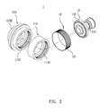
- Fig. 2 is an exploded perspective view showing the assembling relations between each elements of the harmonic reducer of the present invention.
- Fig. 3 is a plane section view showing the structure of the harmonic reducer of the present invention.
- Fig. 4 is a plane schematic view showing one end of the harmonic reducer of the present invention.
- the harmonic reducer with stationary flexspline 1 comprises a stationary spline 11A, a circular spline 11B, a flexspline 12 and a wave generator 13.
- the stationary spline 11A and the circular spline 11B both dispose an internal space, wherein a first internal gear 11A1 composed of a plurality of first internal gear tooth is formed in the inner circumferential wall of the stationary gear 11A, and a second internal gear 11B1 composed of a plurality of second internal gear tooth is formed in the inner circumferential wall of the circular spline 11B.
- the circular spline 11B is axially connected to an output shaft 11B2.
- the stationary gear 11A and the circular spline 11B are abutted axially against each other, and then the stationary gear 11A is mounted to the casing of the reducer (not shown in graph).
- the circular spline 11B can rotate relatively to the stationary gear 11A.
- the flexspline 12 is a thin-walled cylinder manufactured from tubular material with suitable thickness, or is a thin-walled cylinder made from forging and lathing process.
- the outer circumferential surface is then shaped into external gear 121 with a gear hobbing machine.
- the number of the gear teeth of the external gear 121 is equal to the number of the gear teeth of the first internal gear 11A1 in the stationary 11A, but not to the second internal gear 11B1 in the circular spline 11B. In other words, there is a difference in the number of gear teeth between the first internal gear 11A1 and the second internal gear 11B1.
- the flexspline 12 is then assembled in the internal space of the stationary gear 11A and the circular spline 11B.
- the wave generator 13 of the present invention is a deformable bearing which disposes a central axis 131 and an outer ring 132, wherein the central axis 131 is an oval that is close to a circle in shape so the mutual rotation is allowed between the outer ring 132 and the central axis 131.
- the central axis is connected to a power source (not shown in graph) which is normally a motor.
- the flexspline 12 is assembled in the internal space of the stationary gear 11A and the circular spline 11B which are axially abutted, and the wave generator 13 is installed in the inner perimeter of the flexspline 12.
- the flexspline 12 is a thin-walled gear which can be greater elastically deformed, and the inner diameter of the flexspline 12 is equal or slightly greater than the total outer diameter of the wave generator 13, while the wave generator 13 is a component which can deforms the flexspline elastically in a controllable range.
- the ends of the flexspline 12 is forced from the circular shape into an oval shape (as shown in Fig. 4 ).
- the external gear 121 near the two ends of the long axis of the oval is further pushed and engages with the first internal gear 11A1 of the stationary gear 11A and the second internal gear 11B1 of the circular spline 11B completely, whereas the external gear near the two ends of the short axis of the oval is completely disengaged with the first internal gear of the stationary gear and the second internal gear of the circular spline.
- the rest of the external gear on the other parts of the perimeter is in a transition state between engaged and disengaged with the first internal gear 11A1 of the stationary gear 11A and the second internal gear 11B1 of the circular gear 11B.
- the wave generator 13 rotates continuously, the deformation of the flexspline 12 changes continuously, so the engaging status of flexspline 12, the stationary gear 11A and the circular spline 11B also changes constantly.
- the cycle of the engagement starts from engaging in, engaged, engaging out, disengaged and then repeats onwards so the flexspline 12 slowly rotates in the same direction of the wave generator 13 in relative to the circular spline 11B.
- the flexspline 12 deforms but does not rotate in relative to the stationary gear 11A, which means there is no difference of the relative rotation speed between the flexspline 12 and the stationary gear 11A.
- the number of gear teeth between the flexspline 12 and the second internal gear 11B1 of the circular spline 11B are not equal, thus the flexspline 12 deforms and rotates in relative to the circular spline 11B, which means a difference in the relative rotation speed will occur between the flexspline 12 and the circular spline 11B.
- the output shaft 11B2 connected to the circular spline B is then rotating in a reducing speed.
- the loading on the gears can be spread out evenly so the loading can be lowered and the force applied can be more even; thereby the noise and the gear wear can be reduced to prolong the life of use, and the number of the components can also be decreased to lower the production cost.
Landscapes
- Engineering & Computer Science (AREA)
- General Engineering & Computer Science (AREA)
- Mechanical Engineering (AREA)
- Retarders (AREA)
Applications Claiming Priority (1)
| Application Number | Priority Date | Filing Date | Title |
|---|---|---|---|
| TW101211508U TWM440369U (en) | 2012-06-14 | 2012-06-14 | Harmonic reducer with fixed gear |
Publications (1)
| Publication Number | Publication Date |
|---|---|
| EP2674642A1 true EP2674642A1 (fr) | 2013-12-18 |
Family
ID=47716764
Family Applications (1)
| Application Number | Title | Priority Date | Filing Date |
|---|---|---|---|
| EP12183381.8A Withdrawn EP2674642A1 (fr) | 2012-06-14 | 2012-09-06 | Harmonic drive avec pignon stationnaire |
Country Status (3)
| Country | Link |
|---|---|
| US (1) | US20130333505A1 (fr) |
| EP (1) | EP2674642A1 (fr) |
| TW (1) | TWM440369U (fr) |
Cited By (1)
| Publication number | Priority date | Publication date | Assignee | Title |
|---|---|---|---|---|
| EP3885611A4 (fr) * | 2018-12-11 | 2022-06-08 | Technology AICI (Shenzhen) Co. Ltd. | Réducteur d'harmoniques à deux couronnes déformables, à quantité de déformation limitée |
Families Citing this family (4)
| Publication number | Priority date | Publication date | Assignee | Title |
|---|---|---|---|---|
| US8888374B1 (en) * | 2013-05-08 | 2014-11-18 | Hiwin Technologies Corp. | Bearing with antiskid design |
| US20160305528A1 (en) * | 2015-04-20 | 2016-10-20 | Nabors Lux Finance 2 Sarl | Harmonic Gear Drive |
| CA2927596A1 (fr) * | 2015-04-20 | 2016-10-20 | Nabors Lux Finance 2 Sarl | Transmission harmonique |
| JP7085822B2 (ja) * | 2017-11-28 | 2022-06-17 | 住友重機械工業株式会社 | ギヤモータ及びその組立方法 |
Citations (2)
| Publication number | Priority date | Publication date | Assignee | Title |
|---|---|---|---|---|
| EP2003368A2 (fr) * | 2006-03-31 | 2008-12-17 | JTEKT Corporation | Dispositif d'engrenage du type à engrènement flexible et dispositif de direction pour véhicule |
| DE102010007668A1 (de) * | 2009-02-12 | 2010-11-04 | Ovalo Gmbh | Getriebeelement für ein Spannungswellengetriebe, Nockenwellenversteller sowie Lenkkrafthilfe |
-
2012
- 2012-06-14 TW TW101211508U patent/TWM440369U/zh not_active IP Right Cessation
- 2012-09-06 EP EP12183381.8A patent/EP2674642A1/fr not_active Withdrawn
- 2012-09-07 US US13/607,286 patent/US20130333505A1/en not_active Abandoned
Patent Citations (2)
| Publication number | Priority date | Publication date | Assignee | Title |
|---|---|---|---|---|
| EP2003368A2 (fr) * | 2006-03-31 | 2008-12-17 | JTEKT Corporation | Dispositif d'engrenage du type à engrènement flexible et dispositif de direction pour véhicule |
| DE102010007668A1 (de) * | 2009-02-12 | 2010-11-04 | Ovalo Gmbh | Getriebeelement für ein Spannungswellengetriebe, Nockenwellenversteller sowie Lenkkrafthilfe |
Non-Patent Citations (1)
| Title |
|---|
| DEGEN R ET AL: "PANCAKE SHAPED MICRO GEAR SYSTEM WITH HIGH TRANSMISSION RATIO", ACTUATOR. PROCEEDINGS OF INTERNATIONAL TECHNOLOGY TRANSFERCONGRESS, XX, XX, 19 June 2000 (2000-06-19), pages 185 - 188, XP008015661 * |
Cited By (1)
| Publication number | Priority date | Publication date | Assignee | Title |
|---|---|---|---|---|
| EP3885611A4 (fr) * | 2018-12-11 | 2022-06-08 | Technology AICI (Shenzhen) Co. Ltd. | Réducteur d'harmoniques à deux couronnes déformables, à quantité de déformation limitée |
Also Published As
| Publication number | Publication date |
|---|---|
| US20130333505A1 (en) | 2013-12-19 |
| TWM440369U (en) | 2012-11-01 |
Similar Documents
| Publication | Publication Date | Title |
|---|---|---|
| US8869651B2 (en) | Harmonic reducer with clutch function | |
| US20130333515A1 (en) | Flexspline mounting structure of harmonic reducer | |
| EP2672146A1 (fr) | Harmonic drive avec flexspine stationnaire | |
| US9005065B2 (en) | Two-stage differential cycloidal speed reducer with a high reduction ratio | |
| CN109027180B (zh) | 减速器和机器人 | |
| CN108036034B (zh) | 一种双向输出型谐波减速装置 | |
| US10281007B2 (en) | Speed reducer | |
| EP2808581A1 (fr) | Appareil d'entraînement de roue | |
| CN104343894B (zh) | 减速传动轴承 | |
| KR101606863B1 (ko) | 로봇 디스크 커플링 정밀 감속기 | |
| EP2674642A1 (fr) | Harmonic drive avec pignon stationnaire | |
| EP3034907A1 (fr) | Réducteur | |
| CN106461028B (zh) | 波动齿轮装置的波动发生器及波动发生器的制造方法 | |
| JP6220757B2 (ja) | 内接式遊星歯車装置 | |
| CN108843746B (zh) | 一种用于机械人的精密减速器 | |
| JP2005054981A (ja) | ハーモニックドライブ減速機、該減速機付きモータおよび駆動システム | |
| US20130333516A1 (en) | Flexspline structure of harmonic reducer | |
| JP2012251603A (ja) | 摩擦伝動式波動変速機 | |
| CN117307685A (zh) | 一种高减比微型减速装置 | |
| CN102242795A (zh) | 精密摆线减速器 | |
| JP2018159458A (ja) | 波動歯車減速機および内燃機関の可変圧縮装置のアクチュエータ | |
| CN202707948U (zh) | 具有固定齿轮的谐波减速器 | |
| CN111590553B (zh) | 一种谐波减速器及驱动器 | |
| EP3812615B1 (fr) | Transmission reducteur | |
| CN100436867C (zh) | 活齿端面谐波齿轮传动装置 |
Legal Events
| Date | Code | Title | Description |
|---|---|---|---|
| PUAI | Public reference made under article 153(3) epc to a published international application that has entered the european phase |
Free format text: ORIGINAL CODE: 0009012 |
|
| AK | Designated contracting states |
Kind code of ref document: A1 Designated state(s): AL AT BE BG CH CY CZ DE DK EE ES FI FR GB GR HR HU IE IS IT LI LT LU LV MC MK MT NL NO PL PT RO RS SE SI SK SM TR |
|
| AX | Request for extension of the european patent |
Extension state: BA ME |
|
| STAA | Information on the status of an ep patent application or granted ep patent |
Free format text: STATUS: THE APPLICATION IS DEEMED TO BE WITHDRAWN |
|
| 18D | Application deemed to be withdrawn |
Effective date: 20140619 |