EP2003370A2 - Zugspindelmechanismus und lenkvorrichtung - Google Patents
Zugspindelmechanismus und lenkvorrichtung Download PDFInfo
- Publication number
- EP2003370A2 EP2003370A2 EP07737990A EP07737990A EP2003370A2 EP 2003370 A2 EP2003370 A2 EP 2003370A2 EP 07737990 A EP07737990 A EP 07737990A EP 07737990 A EP07737990 A EP 07737990A EP 2003370 A2 EP2003370 A2 EP 2003370A2
- Authority
- EP
- European Patent Office
- Prior art keywords
- feed
- feed screw
- nut
- shaft
- screw shaft
- Prior art date
- Legal status (The legal status is an assumption and is not a legal conclusion. Google has not performed a legal analysis and makes no representation as to the accuracy of the status listed.)
- Withdrawn
Links
- 230000007246 mechanism Effects 0.000 title claims description 145
- 229920003002 synthetic resin Polymers 0.000 claims description 35
- 239000000057 synthetic resin Substances 0.000 claims description 35
- 239000000463 material Substances 0.000 claims description 24
- 229910052751 metal Inorganic materials 0.000 claims description 24
- 239000002184 metal Substances 0.000 claims description 24
- 230000004323 axial length Effects 0.000 claims description 15
- 230000002093 peripheral effect Effects 0.000 claims description 11
- 230000009477 glass transition Effects 0.000 claims description 10
- 238000012840 feeding operation Methods 0.000 abstract description 7
- 239000011295 pitch Substances 0.000 description 44
- 238000003825 pressing Methods 0.000 description 32
- 230000008859 change Effects 0.000 description 24
- 229920005989 resin Polymers 0.000 description 18
- 239000011347 resin Substances 0.000 description 18
- 230000003247 decreasing effect Effects 0.000 description 17
- 238000004519 manufacturing process Methods 0.000 description 15
- 238000010008 shearing Methods 0.000 description 13
- 238000010586 diagram Methods 0.000 description 9
- 239000004734 Polyphenylene sulfide Substances 0.000 description 6
- 229920000069 polyphenylene sulfide Polymers 0.000 description 6
- 102200082816 rs34868397 Human genes 0.000 description 6
- 238000012360 testing method Methods 0.000 description 6
- 229910052782 aluminium Inorganic materials 0.000 description 5
- XAGFODPZIPBFFR-UHFFFAOYSA-N aluminium Chemical compound [Al] XAGFODPZIPBFFR-UHFFFAOYSA-N 0.000 description 5
- 229920003233 aromatic nylon Polymers 0.000 description 5
- 102220005308 rs33960931 Human genes 0.000 description 5
- 230000008602 contraction Effects 0.000 description 4
- 239000003365 glass fiber Substances 0.000 description 4
- 239000004519 grease Substances 0.000 description 3
- RTZKZFJDLAIYFH-UHFFFAOYSA-N Diethyl ether Chemical compound CCOCC RTZKZFJDLAIYFH-UHFFFAOYSA-N 0.000 description 2
- XEEYBQQBJWHFJM-UHFFFAOYSA-N Iron Chemical compound [Fe] XEEYBQQBJWHFJM-UHFFFAOYSA-N 0.000 description 2
- 239000004962 Polyamide-imide Substances 0.000 description 2
- 229920006121 Polyxylylene adipamide Polymers 0.000 description 2
- 229910000831 Steel Inorganic materials 0.000 description 2
- 125000003118 aryl group Chemical group 0.000 description 2
- 238000000034 method Methods 0.000 description 2
- 229920006111 poly(hexamethylene terephthalamide) Polymers 0.000 description 2
- 229920002312 polyamide-imide Polymers 0.000 description 2
- 229920001721 polyimide Polymers 0.000 description 2
- 239000009719 polyimide resin Substances 0.000 description 2
- 229910001220 stainless steel Inorganic materials 0.000 description 2
- 239000010935 stainless steel Substances 0.000 description 2
- 239000010959 steel Substances 0.000 description 2
- 229910001369 Brass Inorganic materials 0.000 description 1
- 239000004696 Poly ether ether ketone Substances 0.000 description 1
- 239000004952 Polyamide Substances 0.000 description 1
- 239000004721 Polyphenylene oxide Substances 0.000 description 1
- 239000004793 Polystyrene Substances 0.000 description 1
- -1 S45C Chemical compound 0.000 description 1
- 230000008901 benefit Effects 0.000 description 1
- JUPQTSLXMOCDHR-UHFFFAOYSA-N benzene-1,4-diol;bis(4-fluorophenyl)methanone Chemical compound OC1=CC=C(O)C=C1.C1=CC(F)=CC=C1C(=O)C1=CC=C(F)C=C1 JUPQTSLXMOCDHR-UHFFFAOYSA-N 0.000 description 1
- 239000010951 brass Substances 0.000 description 1
- 230000007423 decrease Effects 0.000 description 1
- 229910052742 iron Inorganic materials 0.000 description 1
- 150000002576 ketones Chemical class 0.000 description 1
- 238000012986 modification Methods 0.000 description 1
- 230000004048 modification Effects 0.000 description 1
- 239000004033 plastic Substances 0.000 description 1
- 229920003023 plastic Polymers 0.000 description 1
- 229920002647 polyamide Polymers 0.000 description 1
- 229920000570 polyether Polymers 0.000 description 1
- 229920002530 polyetherether ketone Polymers 0.000 description 1
- 239000002861 polymer material Substances 0.000 description 1
- 229920002223 polystyrene Polymers 0.000 description 1
Images


Classifications
-
- B—PERFORMING OPERATIONS; TRANSPORTING
- B62—LAND VEHICLES FOR TRAVELLING OTHERWISE THAN ON RAILS
- B62D—MOTOR VEHICLES; TRAILERS
- B62D1/00—Steering controls, i.e. means for initiating a change of direction of the vehicle
- B62D1/02—Steering controls, i.e. means for initiating a change of direction of the vehicle vehicle-mounted
- B62D1/16—Steering columns
- B62D1/18—Steering columns yieldable or adjustable, e.g. tiltable
- B62D1/181—Steering columns yieldable or adjustable, e.g. tiltable with power actuated adjustment, e.g. with position memory
-
- F—MECHANICAL ENGINEERING; LIGHTING; HEATING; WEAPONS; BLASTING
- F16—ENGINEERING ELEMENTS AND UNITS; GENERAL MEASURES FOR PRODUCING AND MAINTAINING EFFECTIVE FUNCTIONING OF MACHINES OR INSTALLATIONS; THERMAL INSULATION IN GENERAL
- F16H—GEARING
- F16H25/00—Gearings comprising primarily only cams, cam-followers and screw-and-nut mechanisms
- F16H25/18—Gearings comprising primarily only cams, cam-followers and screw-and-nut mechanisms for conveying or interconverting oscillating or reciprocating motions
- F16H25/20—Screw mechanisms
- F16H25/2003—Screw mechanisms with arrangements for taking up backlash
-
- F—MECHANICAL ENGINEERING; LIGHTING; HEATING; WEAPONS; BLASTING
- F16—ENGINEERING ELEMENTS AND UNITS; GENERAL MEASURES FOR PRODUCING AND MAINTAINING EFFECTIVE FUNCTIONING OF MACHINES OR INSTALLATIONS; THERMAL INSULATION IN GENERAL
- F16H—GEARING
- F16H25/00—Gearings comprising primarily only cams, cam-followers and screw-and-nut mechanisms
- F16H25/18—Gearings comprising primarily only cams, cam-followers and screw-and-nut mechanisms for conveying or interconverting oscillating or reciprocating motions
- F16H25/20—Screw mechanisms
- F16H25/24—Elements essential to such mechanisms, e.g. screws, nuts
- F16H2025/249—Materials or coatings for screws or nuts
-
- Y—GENERAL TAGGING OF NEW TECHNOLOGICAL DEVELOPMENTS; GENERAL TAGGING OF CROSS-SECTIONAL TECHNOLOGIES SPANNING OVER SEVERAL SECTIONS OF THE IPC; TECHNICAL SUBJECTS COVERED BY FORMER USPC CROSS-REFERENCE ART COLLECTIONS [XRACs] AND DIGESTS
- Y10—TECHNICAL SUBJECTS COVERED BY FORMER USPC
- Y10T—TECHNICAL SUBJECTS COVERED BY FORMER US CLASSIFICATION
- Y10T74/00—Machine element or mechanism
- Y10T74/18—Mechanical movements
- Y10T74/18568—Reciprocating or oscillating to or from alternating rotary
- Y10T74/18576—Reciprocating or oscillating to or from alternating rotary including screw and nut
Definitions
- the present invention relates to a steering apparatus, and more particularly to a steering apparatus that can adjust a tilting position or a telescopic position of a steering wheel by a feeding movement of a feed screw and relates a feed screw mechanism.
- the tilting position or the telescopic position of the steering wheel needs to be adjusted depending on the build or the driving position of a driver.
- a steering apparatus that adjusts the tilting position or the telescopic position by rotating a feed screw shaft with the rotation of an electric motor to linearly move a feed nut screwed to the feed screw shaft.
- a feed screw shaft is formed with metal, a feed nut is molded by a synthetic resin and the feed nut is deformed inward in a radial direction, and the inner periphery of the feed nut is pressed to the outer periphery of the feed screw shaft to eliminate a backlash between the feed screw shaft and the feed nut.
- a coefficient of thermal expansion of the synthetic resin is considerably higher than a coefficient of thermal expansion of the metal. Accordingly, when the working temperature of the steering apparatus is lower than a normal temperature, the feed nut made of the resin is contracted in an axial direction and a radial direction. As a result, the lead of the feed nut is smaller than the lead of the feed screw shaft due to a contraction in the axial direction to increase interference. Further, the inside diameter of the feed nut is reduced more than the outside diameter of the feed screw shaft due to a contraction in the radial direction to increase interference. Accordingly, when the feed screw mechanism operates, the increase of a torque, the variation of a torque and the increase an operating sound arise.
- the feed nut made of the resin is expanded in the axial direction and in the radial direction.
- the lead of the feed nut is larger than the lead of the feed screw shaft due to an expansion in the axial direction to increase the interference.
- the inside diameter of the feed nut is enlarged more than the outside diameter of the feed screw shaft due to an expansion in the radial direction to increase a backlash.
- a steering apparatus having a feed screw mechanism for suppressing an inconvenience of the operation of the feed screw mechanism caused by the temperature change
- the steering apparatus disclosed in the Patent Document 1 is provided with an axial slit having both axial ends opened in bearing parts at both ends in the axial direction of a feed nut. Further, an effective diameter of the feed nut at a central part in the axial direction thereof is set to a large diameter having an interference added in which the feed nut is fastened at a low temperature. An effective diameter of the feed nut at both the ends in the axial direction thereof is set to a small diameter having no space at a normal temperature. A remaining effective diameter in the axial direction is set to an effective diameter that gradually changes from the large diameter to the small diameter.
- the interference in the radial direction of the feed nut can be adjusted to improve the inconvenience of the operation of the feed screw mechanism.
- an interference in the axial direction of a screw due to a lead difference between the feed nut and a feed screw shaft
- a screw length is required to some degree in order to ensure a screw strength.
- the diameter of the nut is compared with the axial length of the nut, the axial length of the nut is longer than the diameter of the nut.
- a feed screw shaft is formed with metal and a feed nut is molded by a synthetic resin to reduce a sliding resistance when the feed nut is screed to the feed screw shaft so that the durability of the feed screw mechanism is improved and an operating sound is reduced during a feeding movement.
- the width of the screw thread of the feed screw shaft and the width of the screw thread of the feed nut of the conventional feed screw mechanism as shown in the Patent Document 2 are formed so as to have the same dimension (half as long as a pitch of the screw thread).
- the material strength of the feed nut made of the synthetic resin is extremely lower than that of the feed screw shaft. Accordingly, since an engaging length of a screw (the length of the feed nut screw in the axial direction) is determined to meet the feed nut low in its material strength, a problem arises that the feed nut is enlarged, the weight of the feed nut is increased and a production cost is increased.
- an elastically deforming part is provided in a bearing member for supporting a worm to apply an axial pressurizing force to the worm by the elastic force of the elastically deforming member, however, the variation of the pressurizing force due to a temperature change cannot be avoided.
- the dimensions of parts are respectively set so that an amount of linear expansion between the centers of a worm made of metal and a worm wheel made of a resin is equal to an amount of linear expansion of a housing made of aluminum to maintain the backlash of the engaging part of the worm and the worm wheel to a suitable value.
- the above-described dimensions are not applied to a feed screw mechanism for supporting a feed nut to freely rotate.
- the feed screw mechanism and the steering apparatus provided by the present invention, since the operating torque is not increased, an output of a motor for driving the feed screw mechanism may be decreased.
- the motor can be made to be compact, a production cost is decreased and a space may be small. Accordingly, a degree of freedom of an arrangement is improved. Further, the structure of the feed nut itself is simple, so that a working cost of the feed nut is reduced.
- a feed screw mechanism including:
- a feed screw mechanism including:
- the feed screw mechanism as set forth in the second aspect of the invention, wherein the pitch of the feed nut is formed to be substantially larger than the pitch of the feed screw shaft within a range of 0.025 % to 0.075 % of the axial length of the feed nut.
- the feed screw mechanism as set forth in the second aspect of the invention, wherein an annular groove is formed in an end face in the axial direction of the feed nut.
- the feed screw mechanism as set forth in the fourth aspect of the invention, wherein an inner peripheral surface of the annular groove is formed so as to have a diameter reduced toward an opening side of the annular groove.
- a glass transition point of the synthetic resin forming the feed nut is a value exceeding an upper limit value of a range of the working temperature of the feed screw mechanism.
- a steering apparatus including:
- a steering apparatus including:
- the steering apparatus as set forth in the eighth aspect of the invention, wherein the pitch of a feed nut is formed to be substantially larger than the pitch of a feed screw shaft within a range of 0.025 % to 0.075 % of the axial length of the feed nut.
- the steering apparatus as set forth in the eighth aspect of the invention, wherein an annular groove is formed in an end face in the axial direction of the feed nut.
- the steering apparatus as set forth in the ten aspect of the invention, wherein an inner peripheral surface of the annular groove is formed so as to have a diameter reduced toward an opening side of the annular groove.
- a glass transition point of the synthetic resin forming the feed nut is a value exceeding an upper limit value of a range of the working temperature of the feed screw mechanism.
- a width of the screw thread of the feed nut of the feed screw mechanism is formed to be larger than a width of the screw thread of the feed screw shaft.
- a fourteenth aspect of the present invention there is provided the steering apparatus as set forth in the thirteenth aspect of the invention, wherein a ratio of the width of the screw thread of the feed nut to the width of the screw thread of the feed screw shaft is formed to be proportional to an inverse number of a material strength of the feed nut and a material strength of the feed screw shaft.
- the steering apparatus as set forth in the thirteenth aspect of the invention, wherein the feed screw shaft is a rolled screw.
- the steering apparatus as set forth in the eighth aspect of the invention, wherein the width of the screw thread of a feed nut of the feed screw mechanism is formed to be larger than the width of the screw thread of the feed screw shaft.
- a ratio of the width of the screw thread of the feed nut to the width of the screw thread of the feed screw shaft is formed to be proportional to an inverse number of a material strength of the feed nut and a material strength of the feed screw shaft.
- the steering apparatus as set forth in the sixteenth aspect of the invention, wherein the feed screw shaft is a rolled screw.
- the pitch of the feed nut made of the synthetic resin is formed to be larger than the pitch of the feed screw shaft made of the metal. Accordingly, even when the working temperature changes, since an operating torque is not increased, the operating torque is not varied and an operating sound is not increased. Since the operating torque is not increased, an output of a motor for driving the feed screw mechanism may be decreased. As a result, the motor can be made to be compact to reduce a production cost and a space may be decreased to improve a degree of freedom of an arrangement. Further, the structure of the feed nut itself is simple, so that a working cost of the feed nut is reduced and a dimension of the feed nut in the axial direction can be shortened.
- the increase of the operating torque arises at a low temperature due to the influence of grease.
- the feed screw mechanism of the present invention has a property that as the working temperature of the feed screw mechanism is higher, the operating torque necessary for operating the feed screw mechanism becomes larger.
- the feed screw mechanism of the present invention is employed for the steering apparatus so that the rise of the operating torque at the low temperature can be suppressed as an entire part of the steering apparatus.
- the feed screw mechanism can be driven by the motor low in its output, the motor can be made to be compact, the production cost can be reduced and the space may be small, the degree of freedom of an arrangement is improved.
- the width of the screw thread of the feed nut of the feed screw mechanism is formed to be larger than the width of the screw thread of the feed screw shaft. Accordingly, the length of the feed nut in the axial direction is short. Consequently, the weight of the feed nut is reduced and a production cost can be reduced.
- the dimensions of the feed nut, a bearing and a housing in the axial direction are set so that the total of the variation of the dimensions of the feed nut and the bearing in the axial direction due to a temperature change is the same as the variation of the dimension of the housing in the axial direction due to the temperature change. Accordingly, the variation of a pressurizing force due to the temperature change is suppressed, the increase of the operating torque or the generation of a hammering sound during rotating the feed nut can be suppressed.
- Fig. 1 is an entire perspective view showing a state that an electric steering apparatus 101 is attached to a vehicle.
- the electric steering apparatus 101 supports a steering shaft 102 to freely rotate.
- the steering shaft 102 has a steering wheel 103 attached to its upper end (a rear side of a vehicle body) and an intermediate shaft 105 connected to a lower end (a front side of the vehicle body) of the steering shaft 102 through a universal joint 104.
- the intermediate shaft 105 has a universal joint 106 connected to its lower end. To the universal joint 106, a steering gear 107 having a rack and pinion mechanism is connected.
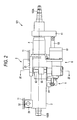
- Fig. 2 is a front view showing main parts of the tilting and telescopic type electric steering apparatus 101.
- Fig. 3 is a sectional view taken along a line III-III of Fig. 2 and showing main parts of a tilt driving mechanism.
- the tilting and telescopic type electric steering apparatus 101 of the present invention includes a vehicle body attaching bracket 2, a lower column (outer column) 3 and an upper column (inner column) 4.
- the vehicle body attaching bracket 2 in the rear side of a vehicle body has an upper plate 21 fixed to the vehicle body 11.
- a bracket 31 is integrally formed in an end part of the lower column 3 in the front side of the vehicle body.
- a tilting center shaft 32 is attached to the bracket 31, a tilting center shaft 32 is attached.
- the end part of the hollow and cylindrical lower column 3 in the front side of the vehicle body is supported on the vehicle body 11 so that a tilting position can be adjusted (swing in a plane parallel to a sheet surface in Fig. 2 )by considering the tilting center shaft 32 to be a fulcrum point.
- the upper column 4 is fitted so that a telescopic position can be adjusted (slide in parallel with a central axis of the lower column 3).
- an upper steering shaft 102A is supported to freely rotate.
- the steering wheel 103 is fixed.
- a lower steering shaft 102B is rotatably supported on the lower column 3.
- the lower steering shaft 102B is spline-connected to the upper steering shaft 102A. Accordingly, the rotation of the upper steering shaft 102A is transmitted to the lower steering shaft 102B irrespective of the telescopic position of the upper column 4.
- the front side of the vehicle body in the lower steering shaft 102B (a left side of Fig. 2 ) is connected to the steering gear 107 (see Fig. 1 ) through the universal joint 104 (see Fig. 1 ).
- the lower steering shaft 102B rotates through the upper steering shaft 102A so that the steering angle of the wheel can be changed.
- right and left side plates are formed that are not shown in the drawing and extend in parallel and downward from the upper plate 21 and the lower column 3 is held between the inner side surfaces of the right and left side plates so as to tilt and slide.
- a telescopic driving mechanism 5 for adjusting a telescopic position is attached to the outer periphery of the lower surface of the lower column 3. Further, in a lower part of the vehicle body attaching bracket 2, a tilt driving mechanism 6 for adjusting a tilting position is attached.
- a worm 62 attached to an output shaft not illustrated of a tilting motor 61 of the tilt driving mechanism 6 is engaged with a worm wheel 64 attached in a lower part of a feed screw shaft 63 (see Fig. 3 ) to transmit the rotation of the tilting motor 61 to the feed screw shaft 63.
- the feed screw shaft 63 extends vertically (in a vertical direction in Figs. 2 and 3 ) to a central axis of the tilting motor 61 and its upper and lower ends are rotatably supported on the vehicle body attaching bracket 2 by bearings 631 and 632.
- a feed nut 65 is screwed to a male screw formed in the outer periphery of the feed screw shaft 63.
- the feed screw shaft 63 and the feed nut 65 form a tilt driving feed screw mechanism.
- a tilt driving force transmitting protrusion 651 is formed integrally.
- the tilt driving force protrusion 651 protrudes toward the central axis of the lower column 3.
- An end of the tilt driving force transmitting protrusion 651 is fitted into an engaging hole 66 formed in the lower column 3.
- a telescopic motor 51 that is partly seen in Fig. 2 is attached.
- a feed screw shaft 53 is attached in parallel with the central axis of the lower column 3 and an end of the feed screw shaft 53 in the rear side of the vehicle body (the right side of Fig. 2 ) is connected to a lower end of a flange 41 fixed to an end of the upper column 4 in the rear side of the vehicle body.
- the rotation of a worm attached to an output shaft not illustrated of the telescopic motor 51 is transmitted to a worm wheel not shown in the drawing to rotate a feed nut that is not illustrated in the drawing and is screwed to the feed screw shaft 53.
- the rotation of the feed nut enables the feed screw shaft 53 to reciprocate (rightward and leftward in Fig. 2 ) so that the telescopic position of the upper column 4 is adjusted.
- the driver when the tilting position of the steering wheel 103 needs to be adjusted, the driver operates a switch that is not shown in the drawing to rotate the tilting motor 61 either in a normal direction or a reverse direction. Then, the feed screw shaft 63 rotates under the rotation of the tilting motor 61 so that the feed nut 65 linearly moves.
- the tilt driving force transmitting protrusion formed integrally with the feed nut 65 carries out the linear movement. Since the tilt driving force transmitting protrusion 651 is engaged with the engaging hole 66 of the lower column 3, the lower column 3 is tilted upward or downward by the tilting center shaft 32 as the fulcrum point.
- this electric steering apparatus 101 when the telescopic position of the steering wheel 103 needs to be adjusted, the driver operates a switch that is not shown in the drawing to rotate the telescopic motor 51 either in a normal direction or a reverse direction. Then, the feed screw shaft 53 moves in parallel with the central axis of the lower column 3 in accordance with the rotation of the telescopic motor 51 so that the upper column 4 carries out a telescopic movement.
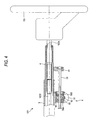
- Fig. 4 is a front view showing main parts of a telescopic type electric steering apparatus 101.
- the telescopic type electric steering apparatus 101 includes a lower column (outer column) 3 and an upper column (inner column) 4.
- the upper column 4 is fitted so that a telescopic position can be adjusted (slide in parallel with a central axis of the lower column 3).
- an upper steering shaft 102A is rotatably supported.
- a steering wheel 103 is fixed to an end part of the upper steering shaft 102A in the rear side (a right side of Fig. 4 ) of a vehicle body.
- a lower steering shaft 102B is rotatably supported on the lower column 3.
- the lower steering shaft 102B is spline-connected to the upper steering shaft 102A. Accordingly, the rotation of the upper steering shaft 102A is transmitted to the lower steering shaft 102B irrespective of the telescopic position of the upper column 4.
- the front side of the vehicle body in the lower steering shaft 102B (a left side of Fig. 4 ) is connected to a steering gear 107 (see Fig. 1 ) through a universal joint 104 (see Fig. 1 ).
- a steering gear 107 (see Fig. 1 )
- a universal joint 104 (see Fig. 1 ).
- a telescopic driving mechanism 5 for adjusting a telescopic position is attached to the lower surface of the lower column 3.
- a feed screw shaft 53 is attached in parallel with the central axis of the lower column 3 and an end of the feed screw shaft 53 in the rear side of the vehicle body (the right end of Fig. 4 ) is connected to a lower end of a flange 41 fixed to an end of the upper column 4 in the rear side of the vehicle body.
- a telescopic motor 51 On the lower surface of the lower column 3, a telescopic motor 51 is attached. The rotation of a worm 52 attached to an output shaft not illustrated of the telescopic motor 51 is transmitted to a worm wheel 54 to rotate a feed nut 55 screwed to the feed screw shaft 53. The feed nut 55 is rotatably supported on the lower surface of the lower column 3 by bearings 56A and 56B.
- a telescopic driving feed screw mechanism is formed by the feed screw shaft 53 and the feed nut 55.
- this electric steering apparatus 101 when the telescopic position of the steering wheel 103 needs to be adjusted, the driver operates a switch that is not shown in the drawing to rotate the telescopic motor 51 either in a normal direction or a reverse direction. Then, the feed screw shaft 53 moves in parallel with the central axis of the lower column 3 in accordance with the rotation of the telescopic motor 51 so that the upper column 4 carries out a telescopic movement.
- Fig. 5 is a partly enlarged sectional view showing a screwed part of a feed screw shaft 63 and a feed nut 65 for tilt driving or of a feed screw shaft 53 and a feed nut 55 for telescopic driving of a first embodiment of the present invention.
- Fig. 5(1) shows a state at a high temperature
- Fig. 5(2) shows a state at a normal temperature
- Fig. 5(3) shows a state at a low temperature.
- the feed screw shafts 53 and 63 are formed with metal such as S45C, S50C or the like.
- the material of the feed screw shafts 53 and 63 may be metal and aluminum or stainless steel may be used.
- the feed nuts 55 and 65 are formed with a synthetic resin such as PPS (polyphenylene sulfide), an aromatic nylon resin, a polyamide imide resin, a polyamide MXD6 resin, a total aromatic polyimide resin, POM, a modified polyamide 6T.
- PPS polyphenylene sulfide
- the nominal size of the feed screw shafts 53 and 63 and the feed nuts 55 and 65 is M12
- a pitch is set to 2 mm
- the axial length of the feed nuts 55 and 65 is set to 20 mm.
- the pitch B2 of the feed nuts 55 and 65 is formed to be slightly larger than the pitch A2 of the feed screw shafts 53 and 63.
- the normal temperature indicates about 10 to 30°C.
- the difference between the pitch B2 and the pitch A2 is desirably set substantially within a range of 0.025 % to 0.075% of the axial length of the feed nuts 55 and 65.
- a pitch B1 of the feed nuts 55 and 65 has the substantially same dimension as that of a pitch A1 of the feed screw shafts 53 and 63. Accordingly, since the interference is not large in the feed nuts 55 and 65 and the feed screw shafts 53 and 63 even at the low temperature, the increase of a torque, the variation of the torque and the increase of an operating sound do not occur and the smooth feeding operation can be carried out.
- the interference between the screw thread of the feed nuts 55 and 65 and the screw thread of the feed screw shafts 53 and 63 is larger than that at the normal temperature.
- the feed nuts 55 and 65 made of the synthetic resin are apt to be bent more under the high temperature than those under the normal temperature. Accordingly, the screw thread of the feed nuts 55 and 65 is bent to suppress the increase of the torque, the variation of the torque and the increase of the operating sound during operating the feed screw mechanism. Thus, the smooth feeding operation can be carried out.
- the Young's modulus is smaller.
- the Young's modulus of Zaitel (a registered trademark) as a kind of the aromatic nylon resin is 10.9 GPa at - 40°C and 7.7 GPa at 80°C. Accordingly, even when the quantity of deformation due to the temperature change is constant and the quantity of deformation at the high temperature is the same as that at the low temperature, the Young's modulus is smaller at the high temperature, so that the stress may be decreased. As a result, the operating torque may be also decreased. Therefore, the provision of the interference at the high temperature makes it more possible to suppress an influence of the interference to the increase of the operating torque to a low level than the provision of the interference at the low temperature.
- the interference acting on the screw thread of the feed nuts 55 and 65 increases under the state of the high temperature, a problem may arise that the creep of the feed nuts 55 and 65 occurs (a phenomenon that when a load is applied at a high temperature, a plastic deformation gradually progresses with the elapse of time).
- the slight interference is provided in the male screw and the female screw at the normal temperature, an interference larger than that conventionally obtained is formed at the high temperature. Thus, in this state, the creep is liable to occur.
- the synthetic resin as a material of the feed nuts 55 and 65, the synthetic resin may be selected whose glass transition point (a phenomenon that a glassy hard state changes to a rubbery state when a polymer material is heated is referred to as a glass transition and a temperature at which the glass transition occurs is referred to as a glass transition point) has a value exceeding an upper limit value within a range of a working temperature of the feed screw mechanism.
- the glass transition point is more effectively located outside the range of the working temperature of the feed screw mechanism than a conventional mechanism.
- polystyrene as a synthetic resin whose glass transition point has a value exceeding 80°C may be selected.
- Fig. 6 is a sectional view showing a screwed part of feed screw shafts 53 and 63 and feed nuts 55 and 65 of a second embodiment of the present invention.
- Fig. 6(1) is a sectional view showing an entire part of the screwed part
- Fig. 6(2) is an enlarged sectional view of a part P in Fig. 6(1)
- Fig. 6(3) is an enlarged sectional view of the part P showing a state when an interference between the screw thread of the feed nut and the screw thread of the feed screw shaft is large.
- the second embodiment is a modified embodiment of the first embodiment.
- annular grooves are formed in both end faces in the axial direction of feed nuts 55 and 65.
- the screw threads of both the end sides of the feed nuts 55 and 65 in the axial direction are bent outward in the radial direction to suppress the increase of a pressure in the screwed part.
- the feed screw shafts 53 and 63 are formed with metal such as S45C, S50C or the like and the feed nuts 55 and 65 are formed with a synthetic resin as in the first embodiment. Further, as shown in Fig. 6(1) , under a state at a normal temperature, a pitch B2 of the feed nuts 55 and 65 is formed to be slightly larger than a pitch A2 of the feed screw shafts 53 and 63.
- annular grooves 72 and 72 are formed in end faces 71A and 71A of the feed nuts 55 and 65 in the axial direction.
- the annular grooves 72 and 72 are formed in a circular ring shape about a central axis 73 of the feed nuts 55 and 65 and a width W of the groove is set to a fixed value.
- the depth H1 of the groove of the annular grooves 72 and 72 is set to a value about 1.5 times of the pitch B2 of the feed nuts 55 and 65.
- the feed nuts 55 and 65 formed with the synthetic resin expand more than the feed screw shafts 53 and 63 made of the metal.
- the interference between the screw thread of the feed nuts 55 and 65 and the screw thread of the feed screw shafts 53 and 63 is large.
- the pitch B2 of the feed nuts 55 and 65 is formed to be slightly larger than the pitch A2 of the feed screw shafts 53 and 63, the screw threads of both the end sides in the axial direction of the feed nuts 55 and 65 are strongly pressed to the screw threads of both the end sides of the feed screw shafts 53 and 63.
- the screw threads of both the end sides in the axial direction of the feed nuts 55 and 65 are bent outward in the radial direction to suppress the excessive increase of the pressure of the screwed part.
- Fig. 7 is a sectional view showing a screwed part of feed screw shafts 53 and 63 and feed nuts 55 and 65 of a third embodiment of the present invention.
- Fig. 7(1) is a sectional view showing an entire part of the screwed part
- Fig. 7(2) is an enlarged sectional view of a part Q in Fig. 7(1)
- Fig. 7(3) is an enlarged sectional view of the part Q showing a state when an interference between the screw thread of the feed nut and the screw thread of the feed screw shaft is large.
- the third embodiment is a modified embodiment of the second embodiment and shows the modified example of the configurations of annular grooves formed in both end faces in the axial direction of the feed nuts 55 and 65.
- the feed screw shafts 53 and 63 are formed with metal such as S45C, S50C or the like and the feed nuts 55 and 65 are formed with a synthetic resin as in the first embodiment and the second embodiment. Further, as shown in Fig. 7(1) , under a state at a normal temperature, a pitch B2 of the feed nuts 55 and 65 is formed to be slightly larger than a pitch A2 of the feed screw shafts 53 and 63.
- annular grooves 74 and 74 are formed in end faces 71A and 71A of the feed nuts 55 and 65 in the axial direction.
- the annular grooves 74 and 74 are formed in a circular ring shape about a central axis 73 of the feed nuts 55 and 65 and formed in a tapered shape so that a groove width W2 in an opening side is larger than a groove width W1 in a groove bottom side.
- the inner peripheral surface 741 of the annular grooves 74 and 74 is formed in a tapered shape (the opening side of the inner peripheral surface 741 has a small diameter).
- an outer peripheral surface 742 may be also formed in a tapered shape (the opening side of the outer peripheral surface 742 has a large diameter).
- the groove depth H2 of the annular grooves 74 and 74 is set to a value about 1.5 times of the pitch B2 of the feed nuts 55 and 65.
- the feed nuts 55 and 65 formed with the synthetic resin expand more than the feed screw shafts 53 and 63 made of the metal.
- the interference between the screw thread of the feed nuts 55 and 65 and the screw thread of the feed screw shafts 53 and 63 is large.
- the pitch B2 of the feed nuts 55 and 65 is formed to be slightly larger than the pitch A2 of the feed screw shafts 53 and 63, the screw threads of both the end sides in the axial direction of the feed nuts 55 and 65 are strongly pressed to the screw threads of both the end sides of the feed screw shafts 53 and 63.
- the screw threads of both the end sides in the axial direction of the feed nuts 55 and 65 are bent outward in the radial direction to suppress the excessive increase of pressure of the screwed part.
- the opening side of the inner peripheral surface 741 of the annular grooves 74 and 74 is formed to have small diameter. Accordingly, as the annular grooves 74 and 74 go nearer to the opening side, the rigidity of the screw thread is more decreased. Therefore, the screw threads at both end sides can be more easily bent outward in the radial direction than those of the embodiment 2.
- the annular grooves 72 or 74 are formed in both the end faces in the axial direction of the feed nuts 55 and 65, however, the annular groove 72 or 74 may be formed in one end face in the axial direction of the feed nuts 55 and 65.
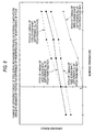
- Fig. 8 is a diagram showing the results of a test carried out to recognize how an operating torque of a feed screw mechanism of the present invention changes depending on a working temperature, so that the difference of characteristics due to the difference of a pitch between the feed nut and the feed screw shaft is inspected and data for determining a proper difference of pitch is obtained.
- the feed screw shaft formed with iron such as S45C, S50C or the like and the feed nut formed with PPS (polyphenylene sulfide) were used.
- the nominal size of the feed screw shaft and the feed nut was M12, the axial length of the feed nut was set to 20 mm and the pitch of the feed nut is set to 2.000 mm at a normal temperature and fixed.
- the pitch of the feed screw shaft four kinds of 1.995 mm, 1.990 mm, 1.985 mm and 1.980 mm were used. That is, four kinds of feed screw mechanisms were used in which the feed nuts were combined with the feed screws so that the pitches of the feed nuts were respectively larger by 5 ⁇ , 10 ⁇ , 15 ⁇ , and 20 ⁇ than the pitches of the feed screw shafts under the state of the normal temperature to recognize how the operating torque of the feed screw mechanisms changes depending on the working temperature.
- the difference in pitch between the feed nut and the feed screw shaft is 20 ⁇
- the operating torque is 0. Since the operating torque of 0 means that a backlash is generated in the feed screw shaft, the operating torque of 0 is not preferable for the characteristics of the feed screw mechanism and the feed screw mechanism for a steering apparatus. Accordingly, the three kinds of the feed screw mechanisms having the difference of the pitch of 5 ⁇ , 10 ⁇ and 15 ⁇ relative to the feed nut are desirable for the steering apparatus. That is, it is recognized that under the state of the normal temperature, the difference in pitch between the feed nut and the feed screw shaft is substantially desirably set within a range of 0.025% to 0.075% of the axial length of the feed nut.
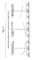
- Fig. 9 is a diagram for explaining the difference between the characteristics of an operating torque of a conventional feed screw mechanism depending on the working temperature and the characteristics of the operating torque of the feed screw mechanism of the present invention depending on the working temperature.
- the pitch of the feed nut made of the synthetic resin is formed to be larger the pitch of the feed screw shaft made of the metal at the normal temperature, since the screw thread of the feed nut is pressed to the screw thread of the feed screw shaft with a small interference at the normal temperature, the operating torque is low.
- the feed nut made of the synthetic resin is more liable to be bent under the state of a high temperature relative to the case under the state of the normal temperature. Accordingly, since the screw thread of the feed nut is bent and the increase of the operating torque is suppressed when the feed screw mechanism operates, a smooth feeding operation can be realized. As a result, the output of a motor for driving the feed screw mechanism may be decreased and the motor can be made to be compact.
- Fig. 10 is a diagram for explaining how the operating torque and the operating force of a conventional steering apparatus change depending on a working temperature.
- Fig. 11 is a diagram for explaining how the operating torque and the operating force of a steering apparatus of the present invention change depending on a working temperature.
- a motor may be made to be compact, a production cost is reduced, space may be decreased and a degree of freedom of an arrangement is improved.
- a lower column 3 is formed by an outer column and an upper column 4 is formed by an inner column, however, the lower column 3 may be formed by the inner column and the upper column 4 may be formed by the outer column.
- Fig. 12 is a partly enlarged sectional view showing a screwed part of a feed screw shaft 63 and a feed nut 65 for the above-described tilt driving or of a feed screw shaft 53 and a feed nut 55 for the telescopic driving.
- the width W2 of the screw thread of the feed nuts 55 and 65 is formed to be larger than the width W1 of the screw thread of the feed screw shafts 53 and 63.
- the width W2 of the screw thread and the width W1 of the screw thread mean the width of the screw thread measured at a position of an effective diameter 71 in a section including an axis 70 of a screw.
- the feed screw shafts 53 and 63 are formed with metal such as S45C, S50C or the like.
- the material of the feed screw shafts 53 and 63 may be metal and aluminum, stainless steel or brass may be used.
- the feed nuts 55 and 65 are formed with a synthetic resin such as PPS (polyphenylene sulfide), an aromatic nylon resin, a polyamide imide resin, a polyamide MXD6 resin, a total aromatic polyimide resin, POM, a modified polyamide 6T, PEEK(polyether.ether.ketone), PA(polyamide), etc.
- the ratio of the width W2 of the screw thread of the feed nuts 55 and 65 to the width W1 of the screw thread of the feed screw shafts 53 and 63 is formed to be proportional to an inverse number of a material strength of the feed nuts 55 and 65 and a material strength of the feed screw shafts 53 and 63.
- Fig. 13 is a partly enlarged sectional view showing one example of a method for calculating the width W1 of the screw thread of the feed screw shafts 53 and 63 and the width W2 of the screw thread of the feed nuts 55 and 65.
- the shearing length of the feed screw shafts 53 and 63 is L1
- the shearing length of the feed nuts 55 and 65 is L2
- the total shearing length of the sharing length L1 and the shearing length L2 is L
- a pitch P of the screw thread is 2.0 mm
- a half angle of the screw thread is 15°
- the shearing strength ⁇ 1 of the feed screw shafts is 400N/mm 2 .
- the shearing strength ⁇ 2 of the feed nuts is 95 N/mm 2 .
- the feed nuts 55 and 65 and the feed screw shafts 53 and 63 have the same withstand load of the screw threads at the screwed position, the axial length (an engaging length)of the feed nuts 55 and 65 LN (see Fig. 12 ) can be shortened. Therefore, the feed nut can be made to be compact, the weight of the feed nut can be reduced, and a production cost can be lowered. Further, since the width W1 of the screw thread of the feed screw shafts 53 and 63 is decreased, the feed screw shaft is lightened and the production cost can be reduced.
- a lower column 3 is formed by an outer column and an upper column 4 is formed by an inner column, however, the lower column 3 may be formed by the inner column and the upper column 4 may be formed by the outer column.
- Fig. 14 is a partly sectional front view showing main parts of a telescopic type electric steering apparatus of a fifth embodiment of the present invention.
- Fig. 15 is a sectional view showing main parts of a telescopic driving mechanism shown in Fig. 14 .
- the telescopic type electric steering apparatus 1101 includes a lower column (outer column) 1003 and an upper column (inner column) 1004.
- a housing 1050 is formed in which a telescopic driving mechanism 1005 for carrying out an adjustment of a telescopic position.
- a round bar shaped feed screw shaft 1053 is arranged in parallel with a central axis of the lower column 1003.
- An end of the feed screw shaft 1053 in a rear part of a vehicle body (a right end in Fig. 14 ) is connected to a lower end of a flange 1041 fixed to the upper column 1004 in the rear side of the vehicle body.
- a telescopic motor 1051 is attached to the housing 1050.
- the rotation of a worm 1052 attached to an output shaft of the telescopic motor 1051 that is not shown in the drawing is transmitted to a worm wheel 1054 to rotate a feed nut 1055 screwed to the feed screw shaft 1053.
- the worm wheel 1054 is formed on the outer periphery of the feed nut 1055.
- the feed nut 1055 is supported on the housing 1050 so as to freely rotate by bearings 1056 and 1057.
- a hole 1501 of a large diameter circular in section is formed in an opening end side (a right side of Fig. 15 ) and a hole 1502 of a small diameter circular in section is formed in a closed end side (a left side of Fig. 15 ).
- an outer ring 1057A of the bearing 1057 is internally fitted.
- an outer ring 1056A of the bearing 1056 whose outside diameter is smaller than the outer ring 1057A of the bearing 1057 is internally fitted.
- a through hole 1506 having a diameter larger than the dimension of the outside diameter of the feed screw shaft 53 is formed and connected to a closed end face 1505 and the feed screw shaft 1053 passes through the through hole 1506 with a space.
- a female screw 1503 is formed in the opening end side and a male screw 1581 formed on an outer periphery of a bearing pressing nut 1058 is screwed to the female screw 1503 to press leftward a right end face 1571A of the outer ring 1057A of the bearing 1057 by a left end face 1582 of the bearing pressing nut 1058.
- a lock nut 1059 is screwed to the male screw 1581 of the bearing pressing nut 1058 to press a left end face 1591 of the lock nut 1059 to a right end face 1504 of the housing 1050 and lock the bearing pressing nut 1058.
- a left end face 1561A of the outer ring 1056A of the bearing 1056 abuts on the closed end face 1505 at the left end of the small diameter hole 1502.
- the dimensions of the outside diameters of a right end face 1551 and a left end face 1552 of the feed nut 1055 are designed to be larger than the dimensions of the inside diameters of an inner ring 1057B of the bearing 1057 and an inner ring 1056B of the bearing 1056 and smaller than the dimensions of the outside diameters of the inner ring 1057B of the bearing 1057 and the inner ring 1056B of the bearing 1056.
- a left end face 1571B of the inner ring 1057B of the bearing 1057 abuts on the right end face 1551 and a right end face 1561B of the inner ring 1056B of the bearing 1056 abuts on the left end face 1552.
- this electric steering apparatus 1101 when the telescopic position of a steering wheel 1103 needs to be adjusted, a driver operates a switch that is not shown in the drawing to rotate the telescopic motor 1051 either in a normal direction or a reverse direction. Then, the rotation of the telescopic motor 51 enables the feed screw shaft 1053 to linearly move in parallel with the central axis of the lower column 1003. Thus, the upper column 1004 carries out a telescopic movement.
- the telescopic driving mechanism 1005 when a temperature changes, axial dimensions respectively change proportionally to the coefficients of linear expansion of materials of the housing 1050, the feed nut 1055, the bearings 1056 and 1057.
- the housing 1050 is formed with aluminum
- the feed nut 1055 is formed with an aromatic nylon resin
- the bearings 1056 and 1057 are formed with bearing steel (SUJ2)
- the coefficients of linear expansion are respectively greatly different. Accordingly, since the variations of the axial dimensions are greatly different, an initially set pressurizing force is changed.
- the dimensions of the parts may be respectively set so that the total of the variations of the axial dimensions of the feed nut 1055 and the bearings 1056 and 1057 is constantly equal to the variation of the axial dimension of the housing 1050 for accommodating the feed nut 1055 and the bearings 1056 and 1057.
- a distance between both the end faces of the bearings 1056 and 1057 of the housing 1050 is A
- a distance between the right end face 1551 and the left end face 1552 of the feed nut 1055 B
- an axial width of the bearing 1056 is C
- an axial width of the bearing 1057 is D.
- a coefficient of linear expansion of the housing 1050 is K1
- a coefficient of linear expansion of the feed nut 1055 is K2
- a coefficient of linear expansion of the bearings 1056 and 1957 K3
- A B + C + D
- the distance A between both the end faces of the bearings 1056 and 1057 of the housing 1050, the distance B between the right end face 1551 and the left end face 1552 of the feed nut 1055, the axial width C of the bearing 1056 and the axial width D of the bearing 1057 may be set so as to satisfy the two equations at the same time.
- the coefficient of linear expansion K1 of the housing 1050 is 2.36 X 10 -5
- the coefficient of linear expansion K2 of the feed nut 1055 is 4 x 10 -5
- the coefficient of linear expansion K3 of the bearings 1056 and 1057 is 1.17 x10 5
- the distance B between the right end face 1551 and the left end face 1552 of the feed nut 1055, the axial width C of the bearing 1056 and the axial width D of the bearing 1057 may be set so as to satisfy this equation.
- the dimensions of the parts cannot be respectively set so as to satisfy the above-described two equations at the same time owing to the restriction of a layout of the telescopic driving mechanism 1005.
- a glass fiber is added to the feed nut 1055 made of the resin to change the coefficient of linear expansion K2 of the feed nut 1055.
- a quantity of addition of the glass fiber is preferably 30 to 70 mass %.
- Fig. 16 is a partly sectional front view showing main parts of a telescopic type electric steering apparatus of a sixth embodiment of the present invention.
- Fig. 17 is a sectional view showing main parts of a telescopic driving mechanism shown in Fig. 16 .
- a structural part and an operation different from those of the above-described embodiments will be described and a duplicated explanation will be omitted. Further, the same parts as those of the above-described embodiments are designated by the same reference numerals and described.
- the sixth embodiment is an example in which an outer ring 1057A of a bearing 1057 in an opening end side is supported not by a housing 1050 but by a bearing pressing nut 1058.
- an upper column 1004 is fitted so that a telescopic position can be adjusted (slide in parallel with a central axis of the lower column 3).
- an upper steering shaft 1102A is supported to freely rotate.
- a steering wheel 1103 is fixed to an end part of the upper steering shaft 1102A in the rear side (a right side of Fig. 16 ) of a vehicle body.
- a lower steering shaft 1102B is supported to freely rotate.
- the lower steering shaft 1102B is spline-connected to the upper steering shaft 1102A. Accordingly, the rotation of the upper steering shaft 1102A is transmitted to the lower steering shaft 1102B irrespective of the telescopic position of the upper column 1004.
- a housing 1050 is formed in which a telescopic driving mechanism 1005 for adjusting a telescopic position is incorporated.
- a round bar shaped feed screw shaft 1053 is arranged in parallel with the central axis of the lower column 1003 and an end of the feed screw shaft 1053 in the rear side of the vehicle body (the right end of Fig. 16 ) is connected to a lower end of a flange 1041 fixed to the upper column 1004 in the rear side of the vehicle body.
- a telescopic motor 1051 is attached to the housing 1050.
- the rotation of a worm 1052 attached to an output shaft not illustrated of the telescopic motor 1051 is transmitted to a worm wheel 1054 to rotate a feed nut 1055 screwed to the feed screw shaft 1053.
- the worm wheel 1054 is formed on the outer periphery of the feed nut 1055.
- the feed nut 1055 is rotatably supported by bearings 1056 and 1057.
- a hole 1501 of a large diameter circular in section is formed in an opening end side (a right side of Fig. 17 ) and a hole 1502 of a small diameter circular in section is formed in a closed end side (a left side of Fig. 17 ).
- a female screw 1503 is formed in the opening end side and a male screw 1581 formed on the outer periphery of a bearing pressing nut 1058 is screwed to the female screw 1503.
- a bearing hole 1583 is formed in a left part of the bearing pressing nut 1058.
- an outer ring 1057A of the bearing 1057 is internally fitted.
- an outer ring 1056A of the bearing 1056 whose outside diameter is the same as that of an outer ring 1057A of the bearing 1057 is internally fitted. That is, the bearing 1056 and the bearing 1057 are common parts.
- the bearing pressing nut 1058 presses leftward the right end face 1571A of the outer ring 1057A of the bearing 1057 by a step surface 1584 of the bearing hole 1583.
- a lock nut 1059 is screwed to the male screw 1581 of the bearing pressing nut 1058 to press a left end face 1591 of the lock nut 1059 to a right end face 1504 of the housing 1050 and lock the bearing pressing nut 1058.
- the feed nut 1055 and the bearings 1056 and 1067 are respectively different, coefficients of linear expansion are respectively greatly different.
- a left end face 1561A of the outer ring 1056A of the bearing 1056 abuts on a closed end face 1505 at the left end of the small diameter hole 1502.
- the right end face 1571A of the outer ring 1057A of the bearing 1057 is pressed leftward by the step surface 1584 of the bearing pressing nut 1058, its pressing force is transmitted to the closed end face 1505 at the left end of the small diameter hole 1502 through the left end face 1571B of an inner ring 1057B of the bearing 1057,the right end face 1551 of the feed nut 1055, the left end face 1552 of the feed nut 1055, the right end face 1561B of an inner ring 1056B of the bearing 1056 and the left end face 1561A of the outer ring 1056A of the bearing 1056. Accordingly, a proper pressurizing force can be applied to the bearings 1056 and 1057.
- a distance between both the end faces of the bearings 1056 and 1057 of the housing 1050 is A
- a distance between the right end face 1551 and the left end face 1552 of the feed nut 1055 is B
- an axial width of the bearing 1056 is C
- an axial width of the bearing 1057 is D.
- a coefficient of linear expansion of the housing 1050 is K1
- a coefficient of linear expansion of the feed nut 1055 is K2
- a coefficient of linear expansion of the bearings 1056 and 1957 K3
- A B + C + D
- the distance A between both the end faces of the bearings 1056 and 1057 of the housing 1050, the distance B between the right end face 1551 and the left end face 1552 of the feed nut 1055, the axial width C of the bearing 1056 and the axial width D of the bearing 1057 may be set so as to satisfy the two equations at the same time.
- the telescopic driving mechanism 1005 can be made to be compact and the bearing 1056 and the bearing 1057 can be made to be common parts. Thus, the number of the parts can be reduced.
- Fig. 18 is a partly sectional front view showing main parts of a telescopic type electric steering apparatus of a seventh embodiment of the present invention.
- Fig. 19 is a sectional view showing main parts of a telescopic driving mechanism shown in Fig. 18 .
- a structural part and an operation different from those of the above-described embodiments will be described and a duplicated explanation will be omitted. Further, the same parts as those of the above-described embodiments are designated by the same reference numerals and described.
- the seventh embodiment is a modified embodiment of the sixth embodiment in which an outer ring 1057A of a bearing 1057 in an opening end side is supported by a bearing pressing nut 1058 and the outside diameter of the outer ring 1057A of the bearing 1057 in the opening end side is smaller than the outside diameter of an outer ring 1056A of a bearing 1056 in a closed end side.
- a housing 1050 is formed in which a telescopic driving mechanism 1005 for adjusting a telescopic position is incorporated.
- a round bar shaped feed screw shaft 1053 is arranged in parallel with the central axis of the lower column 1003 and an end of the feed screw shaft 1053 in the rear side of a vehicle body (a right end of Fig. 18 ) is connected to a lower end of a flange 1041 fixed to an upper column 1004 in the rear side of the vehicle body.
- a telescopic motor 1051 is attached to the housing 1050.
- the rotation of a worm 1052 attached to an output shaft not illustrated of the telescopic motor 1051 is transmitted to a worm wheel 1054 to rotate a feed nut 1055 screwed to the feed screw shaft 1053.
- the worm wheel 1054 is formed on the outer periphery of the feed nut 1055.
- the feed nut 1055 is supported by the bearings 1056 and 1057 to freely rotate.
- a hole 1501 of a large diameter circular in section is formed in an opening end side (a right side of Fig. 19 ) and a hole 1502 of a small diameter circular in section is formed in a closed end side (a left side of Fig. 19 ).
- a female screw 1503 is formed in the opening end side and a male screw 1581 formed on the outer periphery of a bearing pressing nut 1058 is screwed to the female screw 1503.
- the outer ring 1056A of the bearing 1056 is internally fitted.
- a bearing hole 1585 is formed that has a diameter smaller than the inside diameter of the small diameter hole 1502.
- an outer ring 1057A of the bearing 1057 is internally fitted.
- the outside diameter of the outer ring 1057A of the bearing 1057 is formed to be smaller than that of the outer ring 1056A of the bearing 1056.
- the bearing pressing nut 1058 presses leftward the right end face 1571A of the outer ring 1057A of the bearing 1057 by a step surface 1586 of the bearing hole 1585.
- a lock nut 1059 is screwed to the male screw 1581 of the bearing pressing nut 1058 to press a left end face 1591 of the lock nut 1059 to a right end face 1504 of the housing 1050 and lock the bearing pressing nut 1058.
- the feed nut 1055 and the bearings 1056 and 1067 are respectively different, coefficients of linear expansion are respectively greatly different.
- a left end face 1561A of the outer ring 1056A of the bearing 1056 abuts on a closed end face 1505 at the left end of the small diameter hole 1502.
- the right end face 1571A of the outer ring 1057A of the bearing 1057 is pressed leftward by the step surface 1586 of the bearing pressing nut 1058, its pressing force is transmitted to the closed end face 1505 at the left end of the small diameter hole 1502 through the left end face 1571B of an inner ring 1057B of the bearing 1057,the right end face 1551 of the feed nut 1055, the left end face 1552 of the feed nut 1055, the right end face 1561B of an inner ring 1056B of the bearing 1056 and the left end face 1561A of the outer ring 1056A of the bearing 1056. Accordingly, a proper pressurizing force can be applied to the bearings 1056 and 1057.
- a distance between both the end faces of the bearings 1056 and 1057 of the housing 1050 is A
- a distance between the right end face 1551 and the left end face 1552 of the feed nut 1055 is B
- an axial width of the bearing 1056 is C
- an axial width of the bearing 1057 is D.
- a coefficient of linear expansion of the housing 1050 is K1
- a coefficient of linear expansion of the feed nut 1055 is K2
- a coefficient of linear expansion of the bearings 1056 and 1957 is K3
- A B + C + D
- a ⁇ K ⁇ 1 B ⁇ K ⁇ 2 + ( C + D ) ⁇ K ⁇ 3 are established.
- the distance A between both the end faces of the bearings 1056 and 1057 of the housing 1050, the distance B between the right end face 1551 and the left end face 1552 of the feed nut 1055, the axial width C of the bearing 1056 and the axial width D of the bearing 1057 may be set so as to satisfy the two equations at the same time.
- the telescopic driving mechanism 1005 can be made to be more compact.
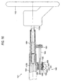
- Fig. 20 is a front view showing main parts of a tilting and telescopic type electric steering apparatus of an eighth embodiment of the present invention.
- Fig. 21 is a sectional view taken along a line XXI-XXI of Fig. 20 and showing main parts of a tilt driving mechanism.
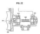
- Fig. 22 is a sectional view taken along a line XXII-XXII of Fig. 21 and showing main parts of a tilting motor and a worm.
- the tilting and telescopic type electric steering apparatus 1101 of the present invention includes a vehicle body attaching bracket 1002 , a lower column (outer column) 1003 and an upper column (inner column) 1004.
- the vehicle body attaching bracket 1002 in the rear side of a vehicle body has an upper plate 1021 fixed to the vehicle body 1011.
- a bracket 1031 is integrally formed in an end part of the lower column 1003 in the front side of the vehicle body.
- a central shaft 1032 of tilting is attached to the bracket 1031.
- the end part of the hollow and cylindrical lower column 1003 in the front side of the vehicle body is supported on the vehicle body 1011 so that a tilting position can be adjusted (swing in a plane parallel to a sheet surface in Fig. 20 )by considering the central shaft 1032 of tilting to be a fulcrum point.
- right and left side plates 1022 and 1022 are formed that extend in parallel and downward from the upper plate 1021 and the lower column 1003 is held between the inner side surfaces of the right and left side plates 1022 and 1022 so as to tilt and slide.
- a telescopic driving mechanism 1005 for adjusting a telescopic position is attached to the outer periphery of the lower surface of the lower column 1003. Further, to the outer periphery of the lower surface of the lower column 1003, a telescopic motor 51 that is partly seen in Fig. 20 is attached. To the lower surface of the lower column 1003, a feed screw shaft 1053 is attached in parallel with the central axis of the lower column 1003 and an end of the feed screw shaft 53 in the rear side of the vehicle body (the right end of Fig. 20 ) is connected to a lower end of a flange 1041 fixed to an end of the upper column 1004 in the rear side of the vehicle body.
- the rotation of a worm attached to an output shaft not illustrated of the telescopic motor 1051 is transmitted to a worm wheel not shown in the drawing to rotate a feed nut that is not illustrated in the drawing and is screwed to the feed screw shaft 1053.
- the rotation of the feed nut enables the feed screw shaft 1053 to reciprocate (rightward and leftward in Fig. 20 ) so that the telescopic position of the upper column 1004 is adjusted. Since the telescopic driving mechanism 1005 has the same structure as that of the fifth embodiment to the seventh embodiment, a detailed description will be omitted.
- a tilt driving mechanism 1006 for adjusting a tilting position is attached in a lower part of the vehicle body attaching bracket 1002.
- a worm 1062 attached to an output shaft 1611 (see Fig. 22 )of a tilting motor 1061 for the tilt driving mechanism 1006 is engaged with a worm wheel 1064 to convert the rotation of the tilting motor 1061 to a reciprocating movement of a feed screw shaft 1063 attached in a lower part of a feed screw shaft 63.
- the worm 1062 is supported on the lower end of the vehicle body attaching bracket 1002 so as to freely rotate by bearings 1612 and 1613.
- a feed nut 1065 having the worm wheel formed on its outer periphery is screwed to the feed screw shaft 1063 (see Fig. 21 ) formed with metal.
- the feed screw shaft 1063 extends vertically (in a vertical direction in Figs. 20 and 21 ) to a central axis of the tilting motor 1061.
- a tilt driving force transmitting pin 1631 made of metal is fixed to an upper end of the feed screw shaft 1063.
- the tilt driving force transmitting pin 1631 protrudes toward the central axis of the lower column 1003 and an end of the tilt driving force transmitting pin 1631 is fitted to a elongated hole 1033 (a long diameter side of the elongated hole 1033 is arranged in the direction intersecting at right angles to the surface of a sheet of Fig. 21 ) formed in the lower column 1003.
- the tilt driving force transmitting pin 1631 linearly moves in a vertical direction together with the feed screw shaft 1063.
- the feed screw shaft 1063 linearly moves in the vertical direction in Fig. 20 .
- the lower column 1003 swings by considering the central shaft 1032 of tilting to be the fulcrum point. Accordingly, a deviation arises between both the movements, however, this deviation can be absorbed by sliding the tilt driving force transmitting pin 1631 along the elongated hole 1033 rightward and leftward in Fig. 20 .
- this electric steering apparatus 1101 when the tilting position of the steering wheel 1003 needs to be adjusted, a driver operates a switch that is not shown in the drawing to rotate the tilting motor 1061 either in a normal direction or a reverse direction. Then, the feed nut 1065 rotates under the rotation of the tilting motor 1061 so that the feed screw shaft 1063 linearly moves.
- the tilt driving force transmitting pin 1631 formed integrally with the feed screw shaft 1063 carries out the linear movement. Since the tilt driving force transmitting pin 1631 is engaged with the elongated hole 1033 of the lower column 1003, the lower column 1003 is tilted upward or downward by considering the central shaft 1032 of tilting to be the fulcrum point.
- a housing 1060 is formed in which the tilt driving mechanism 1006 is incorporated.
- a hole 1601 of a large diameter circular in section is formed in an opening end side (a lower side of Fig. 21 ) and a hole 1602 of a small diameter circular in section is formed in a closed end side (an upper side of Fig. 21 ).
- a female screw 1603 is formed in the opening end side and a male screw 1681 formed on the outer periphery of a bearing pressing nut 1068 is screwed to the female screw 1603.
- an outer ring of a bearing 1066 is internally fitted.
- a bearing hole 1685 is formed that has a diameter smaller than the inside diameter of the small diameter hole 1602.
- an outer ring of a bearing 1067 is internally fitted. The outside diameter of the outer ring of the bearing 1067 is formed to be smaller than the outside diameter of the outer ring of the bearing 1066.
- the bearing pressing nut 1068 presses upward the lower end face of the outer ring of the bearing 1067 by a step surface of the bearing hole 1685.
- a lock nut 1069 is screwed to a male screw 1681 of the bearing pressing nut 1068 to press an upper end face of the lock nut 1069 to the lower end face of the housing 1060 and lock the bearing pressing nut 1068.
- coefficients of linear expansion are respectively greatly different.
- An upper end face of the outer ring of the bearing 1066 abuts on a closed end face at the upper end of the small diameter hole 1602.
- the lower end face of the outer ring of the bearing 1067 is pressed upward by a step surface of the bearing pressing nut 1068, its pressing force is transmitted to the closed end face at the upper end of the small diameter hole 1602 through the upper end face of an inner ring of the bearing 1067,the lower end face of the feed nut 1065, the upper end face of the feed nut 1065, the lower end face of an inner ring of the bearing 1066 and the upper end face of the outer ring of the bearing 1066. Accordingly, a proper pressurizing force can be applied to the bearings 1066 and 1067.
- a distance between both the end faces of the bearings 1066 and 1067 of the housing 1060 is A
- a distance between the lower end face and the upper end face of the feed nut 1065 is B
- an axial width of the bearing 1066 is C
- an axial width of the bearing 1067 is D.
- a coefficient of linear expansion of the housing 1060 is K1
- a coefficient of linear expansion of the feed nut 1065 is K2
- a coefficient of linear expansion of the bearings 1066 and 1967 K3
- A B + C + D
- the distance A between both the end faces of the bearings 1066 and 1067 of the housing 1060, the distance B between the lower end face and the upper end face of the feed nut 1065, the axial width C of the bearing 1066 and the axial width D of the bearing 1067 may be set so as to satisfy the two equations at the same time.
- the tilt driving mechanism 1006 can be made to be more compact.
- the lower column 1003 is formed by an outer column and the upper column 1004 is formed by an inner column.
- the lower column 1003 may be formed by the inner column and the upper column 1004 may be formed by the outer column.
- the pitch of the feed nut made of the synthetic resin is formed to be larger than the pitch of the feed screw shaft made of the metal. Accordingly, even when the working temperature changes, since an operating torque is not increased, the operating torque is not varied and an operating sound is not increased. Since the operating torque is not increased, an output of a motor for driving the feed screw mechanism may be decreased. As a result, the motor can be made to be compact to reduce a production cost and a space may be decreased to improve a degree of freedom of an arrangement. Further, the structure of the feed nut itself is simple, so that a working cost of the feed nut is reduced and a dimension of the feed nut in the axial direction can be shortened.
- the feed screw mechanism of the present invention has a property that as the working temperature of the feed screw mechanism is higher, the operating torque necessary for operating the feed screw mechanism becomes larger. Accordingly, the feed screw mechanism of the present invention is employed for the steering apparatus so that the rise of the operating torque at the low temperature can be suppressed as an entire part of the steering apparatus. As a result, since the feed screw mechanism can be driven by the motor low in its output, the motor can be made to be compact, the production cost can be reduced and the space may be small, the degree of freedom of an arrangement is improved.
- the width of the screw thread of the feed nut of the feed screw mechanism is formed to be larger than the width of the screw thread of the feed screw shaft. Accordingly, the length of the feed nut in the axial direction is short. Consequently, the weight of the feed nut is reduced and a production cost can be reduced.
- the dimensions of the feed nut, a bearing and a housing in the axial direction are set so that the total of the variation of the dimensions of the feed nut and the bearing in the axial direction due to a temperature change is the same as the variation of the dimension of the housing in the axial direction due to the temperature change. Accordingly, the variation of a pressurizing force due to the temperature change is suppressed, the increase of the operating torque or the generation of a hammering sound during rotating the feed nut can be suppressed.
Landscapes
- Engineering & Computer Science (AREA)
- General Engineering & Computer Science (AREA)
- Mechanical Engineering (AREA)
- Chemical & Material Sciences (AREA)
- Combustion & Propulsion (AREA)
- Transportation (AREA)
- Steering Controls (AREA)
- Transmission Devices (AREA)
Applications Claiming Priority (5)
| Application Number | Priority Date | Filing Date | Title |
|---|---|---|---|
| JP2006062225 | 2006-03-08 | ||
| JP2006148175A JP5114869B2 (ja) | 2006-05-29 | 2006-05-29 | ステアリング装置 |
| JP2006177317A JP2008006881A (ja) | 2006-06-27 | 2006-06-27 | ステアリング装置 |
| JP2007001673A JP5151154B2 (ja) | 2006-03-08 | 2007-01-09 | ステアリング装置 |
| PCT/JP2007/054477 WO2007102558A1 (ja) | 2006-03-08 | 2007-03-07 | 送りねじ機構及びステアリング装置 |
Publications (2)
| Publication Number | Publication Date |
|---|---|
| EP2003370A2 true EP2003370A2 (de) | 2008-12-17 |
| EP2003370A9 EP2003370A9 (de) | 2009-04-22 |
Family
ID=38474979
Family Applications (1)
| Application Number | Title | Priority Date | Filing Date |
|---|---|---|---|
| EP07737990A Withdrawn EP2003370A2 (de) | 2006-03-08 | 2007-03-07 | Zugspindelmechanismus und lenkvorrichtung |
Country Status (3)
| Country | Link |
|---|---|
| US (1) | US20090266187A1 (de) |
| EP (1) | EP2003370A2 (de) |
| WO (1) | WO2007102558A1 (de) |
Cited By (2)
| Publication number | Priority date | Publication date | Assignee | Title |
|---|---|---|---|---|
| EP2581209A1 (de) * | 2011-10-14 | 2013-04-17 | Robert Bosch Gmbh | Vorrichtung zum Betreiben eines Presskolbens |
| WO2015154791A1 (de) * | 2014-04-07 | 2015-10-15 | Igus Gmbh | GLEITGEWINDETRIEB MIT ASYMMETRISCHEM INNEN- UND AUßENGEWINDE SOWIE ENTSPRECHENDE SPINDELMUTTER |
Families Citing this family (12)
| Publication number | Priority date | Publication date | Assignee | Title |
|---|---|---|---|---|
| WO2008001721A1 (en) * | 2006-06-29 | 2008-01-03 | Nsk Ltd. | Steering device |
| JP5233246B2 (ja) * | 2007-10-31 | 2013-07-10 | 日本精工株式会社 | 電動テレスコ調整式ステアリング装置 |
| JP5513282B2 (ja) * | 2010-06-29 | 2014-06-04 | 富士機工株式会社 | 電動テレスコステアリング装置 |
| KR101306457B1 (ko) * | 2011-01-17 | 2013-09-09 | 주식회사 만도 | 전동식 틸트 조향장치 |
| DE102014103879A1 (de) * | 2014-03-21 | 2015-09-24 | Thyssenkrupp Presta Ag | Lenksäule für ein Kraftfahrzeug, Gewindestange und Spindelmutter |
| DE102015216326B4 (de) * | 2015-08-26 | 2016-09-08 | Thyssenkrupp Ag | Motorisch verstellbare Lenksäule für ein Kraftfahrzeug |
| DE102017201379A1 (de) * | 2017-01-30 | 2018-08-02 | Thyssenkrupp Ag | Motorisch verstellbare Lenksäule für ein Kraftfahrzeug und Verstellantrieb für eine Lenksäule |
| DE102017215842B4 (de) * | 2017-09-08 | 2025-01-16 | Robert Bosch Gmbh | Verfahren zum Betrieb einer Lenkvorrichtung und Lenkvorrichtung |
| US11390313B2 (en) * | 2020-04-30 | 2022-07-19 | Nsk Ltd. | Electrically adjustable steering column |
| DE102020216255A1 (de) | 2020-12-18 | 2022-06-23 | Robert Bosch Gesellschaft mit beschränkter Haftung | Spindelantrieb sowie Verfahren zur Herstellung eines solchen |
| DE102022203917A1 (de) * | 2021-09-30 | 2023-03-30 | Hl Mando Corporation | Lenksäule für kraftfahrzeuge |
| CN114812826A (zh) * | 2022-05-19 | 2022-07-29 | 深圳美铭高电子有限公司 | 一种方便移动的门式人体测温仪 |
Family Cites Families (22)
| Publication number | Priority date | Publication date | Assignee | Title |
|---|---|---|---|---|
| FR1111508A (fr) * | 1952-06-20 | 1956-03-01 | Perfectionnements aux pièces filetées | |
| DE3421273C2 (de) * | 1983-06-11 | 1987-01-22 | Aisin Seiki K.K., Kariya, Aichi | Wellenbuchseneinheit |
| US4864884A (en) * | 1988-08-01 | 1989-09-12 | Dana Corporation | Ball nut and means for attaching a mounting flange thereto |
| JPH04106546U (ja) * | 1991-02-26 | 1992-09-14 | 光洋機械工業株式会社 | ボールねじ |
| JPH0823B2 (ja) | 1993-06-28 | 1996-01-10 | 哲男 松尾 | 手延べ製麺用延べ機の、熟成コンベヤー |
| JP3379092B2 (ja) | 1994-02-04 | 2003-02-17 | 日本精工株式会社 | 電動式パワーステアリング装置 |
| US5355287A (en) * | 1994-03-10 | 1994-10-11 | Elco Industries, Inc. | Headlamp adjuster with sealed adjusting link |
| JPH0960703A (ja) * | 1995-08-29 | 1997-03-04 | Aisin Seiki Co Ltd | 駆動装置 |
| JP2000238647A (ja) | 1998-12-25 | 2000-09-05 | Nsk Ltd | 電動式ステアリングコラム装置 |
| US6311576B1 (en) * | 1999-10-04 | 2001-11-06 | Techmetric Inc. | Anti-backlash nut for lead screw |
| JP3852268B2 (ja) | 2000-05-01 | 2006-11-29 | 日本精工株式会社 | 電動位置調整式ステアリング装置及びそのネジギヤの加工方法 |
| JP2006148175A (ja) | 2000-09-13 | 2006-06-08 | Hamamatsu Photonics Kk | レーザ加工方法 |
| DE10057302B4 (de) * | 2000-11-17 | 2004-11-18 | Krauss-Maffei Kunststofftechnik Gmbh | Formverriegelungsvorrichtung einer Spritzgießmaschine mit einer zugübertragenden Befestigungsvorrichtung |
| JP4581245B2 (ja) * | 2000-12-26 | 2010-11-17 | 日本精工株式会社 | 車両用電動チルト式ステアリング装置 |
| GB0112984D0 (en) * | 2001-05-30 | 2001-07-18 | Lucas Industries Ltd | Screw actuator |
| JP2003346515A (ja) * | 2002-05-30 | 2003-12-05 | Koito Mfg Co Ltd | 車輌用前照灯のレベリング装置 |
| JP4453807B2 (ja) * | 2003-06-20 | 2010-04-21 | 株式会社ジェイテクト | ボールねじの製造方法 |
| JP2005069430A (ja) * | 2003-08-27 | 2005-03-17 | Kokuei Kogyo:Kk | 直線移動装置 |
| JP2006057794A (ja) * | 2004-08-23 | 2006-03-02 | Nsk Ltd | 遊星ローラネジ装置 |
| JP2006062225A (ja) | 2004-08-27 | 2006-03-09 | Fuji Photo Film Co Ltd | インクジェット記録装置 |
| JP3686672B1 (ja) | 2004-12-24 | 2005-08-24 | 日産ディーゼル工業株式会社 | エンジンの排気浄化装置 |
| JP4710430B2 (ja) | 2005-06-21 | 2011-06-29 | 富士ゼロックス株式会社 | シート供給装置及び画像形成装置 |
-
2007
- 2007-03-07 EP EP07737990A patent/EP2003370A2/de not_active Withdrawn
- 2007-03-07 US US11/910,018 patent/US20090266187A1/en not_active Abandoned
- 2007-03-07 WO PCT/JP2007/054477 patent/WO2007102558A1/ja not_active Ceased
Non-Patent Citations (1)
| Title |
|---|
| See references of WO2007102558A1 * |
Cited By (4)
| Publication number | Priority date | Publication date | Assignee | Title |
|---|---|---|---|---|
| EP2581209A1 (de) * | 2011-10-14 | 2013-04-17 | Robert Bosch Gmbh | Vorrichtung zum Betreiben eines Presskolbens |
| WO2015154791A1 (de) * | 2014-04-07 | 2015-10-15 | Igus Gmbh | GLEITGEWINDETRIEB MIT ASYMMETRISCHEM INNEN- UND AUßENGEWINDE SOWIE ENTSPRECHENDE SPINDELMUTTER |
| EP4325090A2 (de) | 2014-04-07 | 2024-02-21 | igus GmbH | Gleitgewindetrieb mit asymmetrischem innen- und aussengewinde |
| EP4325090A3 (de) * | 2014-04-07 | 2024-04-24 | igus GmbH | Gleitgewindetrieb mit asymmetrischem innen- und aussengewinde |
Also Published As
| Publication number | Publication date |
|---|---|
| US20090266187A1 (en) | 2009-10-29 |
| WO2007102558A1 (ja) | 2007-09-13 |
| EP2003370A9 (de) | 2009-04-22 |
Similar Documents
| Publication | Publication Date | Title |
|---|---|---|
| EP2003370A2 (de) | Zugspindelmechanismus und lenkvorrichtung | |
| EP1760368B1 (de) | Elektrische Servolenkung | |
| EP2279108B1 (de) | Getriebeanordnung für ein elektrisches servolenksystem | |
| US6763738B1 (en) | Electric power steering apparatus | |
| US7559266B2 (en) | Telescopic shaft | |
| US8336413B2 (en) | Rack and pinion steering apparatus having rack bearing wear compensation with damping | |
| JP5104332B2 (ja) | 伸縮軸の製造方法、及び、この製造方法によって製造した伸縮軸 | |
| US11708887B2 (en) | Gearbox assembly | |
| US20130291669A1 (en) | Linear actuator and linear actuating module having same | |
| EP1974154A1 (de) | Reibungsgetriebe-frej | |
| DE102007040857B4 (de) | Drehmomentsensor für ein Lenkrad | |
| US20160017647A1 (en) | Shearing-force mechanism with cross-linked thermoplastic | |
| EP2913245B1 (de) | Elektrische servolenkung | |
| CN101096213A (zh) | 伸缩轴 | |
| JP5151154B2 (ja) | ステアリング装置 | |
| JP4636813B2 (ja) | 回転直動変換機構 | |
| CN101658697A (zh) | 注射泵注射器的识别机构 | |
| EP1992545A1 (de) | Zahnstangengelenkvorrichtung mit Verschleißausgleich für das Stangenlager mit Dämpfung | |
| CN112105544B (zh) | 转向传动机构以及用于制造转向传动机构的方法 | |
| JP7482516B2 (ja) | 撓み継手およびゴニオメータ | |
| CN106940162B (zh) | 一种双轴测角仪 | |
| CN114577456B (zh) | 一种橡胶接头性能测试系统 | |
| CN118578343A (zh) | 全柔性高精度姿态调整组合平台及其应用 | |
| CN112610594A (zh) | 一种低轴漂的柔性轴承及基于轴漂补偿的步进机构 | |
| JP2020180638A (ja) | ボールねじ装置、およびステアリング装置 |
Legal Events
| Date | Code | Title | Description |
|---|---|---|---|
| PUAI | Public reference made under article 153(3) epc to a published international application that has entered the european phase |
Free format text: ORIGINAL CODE: 0009012 |
|
| 17P | Request for examination filed |
Effective date: 20070927 |
|
| AK | Designated contracting states |
Kind code of ref document: A2 Designated state(s): DE GB PL |
|
| PUAB | Information related to the publication of an a document modified or deleted |
Free format text: ORIGINAL CODE: 0009199EPPU |
|
| DAX | Request for extension of the european patent (deleted) | ||
| RBV | Designated contracting states (corrected) |
Designated state(s): DE GB PL |
|
| STAA | Information on the status of an ep patent application or granted ep patent |
Free format text: STATUS: THE APPLICATION HAS BEEN WITHDRAWN |
|
| 18W | Application withdrawn |
Effective date: 20090515 |