EP2003405A2 - Dispositif de fixation pour des composants plats installés sur un bâti, en particulier pour des modules solaires - Google Patents
Dispositif de fixation pour des composants plats installés sur un bâti, en particulier pour des modules solaires Download PDFInfo
- Publication number
- EP2003405A2 EP2003405A2 EP08007003A EP08007003A EP2003405A2 EP 2003405 A2 EP2003405 A2 EP 2003405A2 EP 08007003 A EP08007003 A EP 08007003A EP 08007003 A EP08007003 A EP 08007003A EP 2003405 A2 EP2003405 A2 EP 2003405A2
- Authority
- EP
- European Patent Office
- Prior art keywords
- profile
- component
- fastening device
- region
- holding
- Prior art date
- Legal status (The legal status is an assumption and is not a legal conclusion. Google has not performed a legal analysis and makes no representation as to the accuracy of the status listed.)
- Granted
Links
Images
Classifications
-
- H—ELECTRICITY
- H02—GENERATION; CONVERSION OR DISTRIBUTION OF ELECTRIC POWER
- H02S—GENERATION OF ELECTRIC POWER BY CONVERSION OF INFRARED RADIATION, VISIBLE LIGHT OR ULTRAVIOLET LIGHT, e.g. USING PHOTOVOLTAIC [PV] MODULES
- H02S20/00—Supporting structures for PV modules
- H02S20/20—Supporting structures directly fixed to an immovable object
- H02S20/22—Supporting structures directly fixed to an immovable object specially adapted for buildings
- H02S20/23—Supporting structures directly fixed to an immovable object specially adapted for buildings specially adapted for roof structures
-
- F—MECHANICAL ENGINEERING; LIGHTING; HEATING; WEAPONS; BLASTING
- F24—HEATING; RANGES; VENTILATING
- F24S—SOLAR HEAT COLLECTORS; SOLAR HEAT SYSTEMS
- F24S25/00—Arrangement of stationary mountings or supports for solar heat collector modules
- F24S25/20—Peripheral frames for modules
-
- F—MECHANICAL ENGINEERING; LIGHTING; HEATING; WEAPONS; BLASTING
- F24—HEATING; RANGES; VENTILATING
- F24S—SOLAR HEAT COLLECTORS; SOLAR HEAT SYSTEMS
- F24S25/00—Arrangement of stationary mountings or supports for solar heat collector modules
- F24S25/30—Arrangement of stationary mountings or supports for solar heat collector modules using elongate rigid mounting elements extending substantially along the supporting surface, e.g. for covering buildings with solar heat collectors
- F24S25/33—Arrangement of stationary mountings or supports for solar heat collector modules using elongate rigid mounting elements extending substantially along the supporting surface, e.g. for covering buildings with solar heat collectors forming substantially planar assemblies, e.g. of coplanar or stacked profiles
- F24S25/35—Arrangement of stationary mountings or supports for solar heat collector modules using elongate rigid mounting elements extending substantially along the supporting surface, e.g. for covering buildings with solar heat collectors forming substantially planar assemblies, e.g. of coplanar or stacked profiles by means of profiles with a cross-section defining separate supporting portions for adjacent modules
-
- F—MECHANICAL ENGINEERING; LIGHTING; HEATING; WEAPONS; BLASTING
- F24—HEATING; RANGES; VENTILATING
- F24S—SOLAR HEAT COLLECTORS; SOLAR HEAT SYSTEMS
- F24S25/00—Arrangement of stationary mountings or supports for solar heat collector modules
- F24S25/60—Fixation means, e.g. fasteners, specially adapted for supporting solar heat collector modules
- F24S25/63—Fixation means, e.g. fasteners, specially adapted for supporting solar heat collector modules for fixing modules or their peripheral frames to supporting elements
- F24S25/632—Side connectors; Base connectors
-
- F—MECHANICAL ENGINEERING; LIGHTING; HEATING; WEAPONS; BLASTING
- F24—HEATING; RANGES; VENTILATING
- F24S—SOLAR HEAT COLLECTORS; SOLAR HEAT SYSTEMS
- F24S25/00—Arrangement of stationary mountings or supports for solar heat collector modules
- F24S25/60—Fixation means, e.g. fasteners, specially adapted for supporting solar heat collector modules
- F24S25/63—Fixation means, e.g. fasteners, specially adapted for supporting solar heat collector modules for fixing modules or their peripheral frames to supporting elements
- F24S25/634—Clamps; Clips
-
- F—MECHANICAL ENGINEERING; LIGHTING; HEATING; WEAPONS; BLASTING
- F24—HEATING; RANGES; VENTILATING
- F24S—SOLAR HEAT COLLECTORS; SOLAR HEAT SYSTEMS
- F24S80/00—Details, accessories or component parts of solar heat collectors not provided for in groups F24S10/00-F24S70/00
- F24S80/70—Sealing means
-
- F—MECHANICAL ENGINEERING; LIGHTING; HEATING; WEAPONS; BLASTING
- F24—HEATING; RANGES; VENTILATING
- F24S—SOLAR HEAT COLLECTORS; SOLAR HEAT SYSTEMS
- F24S20/00—Solar heat collectors specially adapted for particular uses or environments
- F24S2020/10—Solar modules layout; Modular arrangements
- F24S2020/13—Overlaying arrangements similar to roof tiles
-
- F—MECHANICAL ENGINEERING; LIGHTING; HEATING; WEAPONS; BLASTING
- F24—HEATING; RANGES; VENTILATING
- F24S—SOLAR HEAT COLLECTORS; SOLAR HEAT SYSTEMS
- F24S25/00—Arrangement of stationary mountings or supports for solar heat collector modules
- F24S2025/01—Special support components; Methods of use
- F24S2025/018—Means for preventing movements, e.g. stops
-
- F—MECHANICAL ENGINEERING; LIGHTING; HEATING; WEAPONS; BLASTING
- F24—HEATING; RANGES; VENTILATING
- F24S—SOLAR HEAT COLLECTORS; SOLAR HEAT SYSTEMS
- F24S25/00—Arrangement of stationary mountings or supports for solar heat collector modules
- F24S2025/01—Special support components; Methods of use
- F24S2025/019—Means for accommodating irregularities on mounting surface; Tolerance compensation means
-
- F—MECHANICAL ENGINEERING; LIGHTING; HEATING; WEAPONS; BLASTING
- F24—HEATING; RANGES; VENTILATING
- F24S—SOLAR HEAT COLLECTORS; SOLAR HEAT SYSTEMS
- F24S25/00—Arrangement of stationary mountings or supports for solar heat collector modules
- F24S25/60—Fixation means, e.g. fasteners, specially adapted for supporting solar heat collector modules
- F24S2025/6002—Fixation means, e.g. fasteners, specially adapted for supporting solar heat collector modules by using hooks
-
- F—MECHANICAL ENGINEERING; LIGHTING; HEATING; WEAPONS; BLASTING
- F24—HEATING; RANGES; VENTILATING
- F24S—SOLAR HEAT COLLECTORS; SOLAR HEAT SYSTEMS
- F24S25/00—Arrangement of stationary mountings or supports for solar heat collector modules
- F24S2025/80—Special profiles
- F24S2025/801—Special profiles having hollow parts with closed cross-section
-
- F—MECHANICAL ENGINEERING; LIGHTING; HEATING; WEAPONS; BLASTING
- F24—HEATING; RANGES; VENTILATING
- F24S—SOLAR HEAT COLLECTORS; SOLAR HEAT SYSTEMS
- F24S25/00—Arrangement of stationary mountings or supports for solar heat collector modules
- F24S2025/80—Special profiles
- F24S2025/807—Special profiles having undercut grooves
-
- Y—GENERAL TAGGING OF NEW TECHNOLOGICAL DEVELOPMENTS; GENERAL TAGGING OF CROSS-SECTIONAL TECHNOLOGIES SPANNING OVER SEVERAL SECTIONS OF THE IPC; TECHNICAL SUBJECTS COVERED BY FORMER USPC CROSS-REFERENCE ART COLLECTIONS [XRACs] AND DIGESTS
- Y02—TECHNOLOGIES OR APPLICATIONS FOR MITIGATION OR ADAPTATION AGAINST CLIMATE CHANGE
- Y02B—CLIMATE CHANGE MITIGATION TECHNOLOGIES RELATED TO BUILDINGS, e.g. HOUSING, HOUSE APPLIANCES OR RELATED END-USER APPLICATIONS
- Y02B10/00—Integration of renewable energy sources in buildings
- Y02B10/10—Photovoltaic [PV]
-
- Y—GENERAL TAGGING OF NEW TECHNOLOGICAL DEVELOPMENTS; GENERAL TAGGING OF CROSS-SECTIONAL TECHNOLOGIES SPANNING OVER SEVERAL SECTIONS OF THE IPC; TECHNICAL SUBJECTS COVERED BY FORMER USPC CROSS-REFERENCE ART COLLECTIONS [XRACs] AND DIGESTS
- Y02—TECHNOLOGIES OR APPLICATIONS FOR MITIGATION OR ADAPTATION AGAINST CLIMATE CHANGE
- Y02B—CLIMATE CHANGE MITIGATION TECHNOLOGIES RELATED TO BUILDINGS, e.g. HOUSING, HOUSE APPLIANCES OR RELATED END-USER APPLICATIONS
- Y02B10/00—Integration of renewable energy sources in buildings
- Y02B10/20—Solar thermal
-
- Y—GENERAL TAGGING OF NEW TECHNOLOGICAL DEVELOPMENTS; GENERAL TAGGING OF CROSS-SECTIONAL TECHNOLOGIES SPANNING OVER SEVERAL SECTIONS OF THE IPC; TECHNICAL SUBJECTS COVERED BY FORMER USPC CROSS-REFERENCE ART COLLECTIONS [XRACs] AND DIGESTS
- Y02—TECHNOLOGIES OR APPLICATIONS FOR MITIGATION OR ADAPTATION AGAINST CLIMATE CHANGE
- Y02E—REDUCTION OF GREENHOUSE GAS [GHG] EMISSIONS, RELATED TO ENERGY GENERATION, TRANSMISSION OR DISTRIBUTION
- Y02E10/00—Energy generation through renewable energy sources
- Y02E10/40—Solar thermal energy, e.g. solar towers
- Y02E10/47—Mountings or tracking
-
- Y—GENERAL TAGGING OF NEW TECHNOLOGICAL DEVELOPMENTS; GENERAL TAGGING OF CROSS-SECTIONAL TECHNOLOGIES SPANNING OVER SEVERAL SECTIONS OF THE IPC; TECHNICAL SUBJECTS COVERED BY FORMER USPC CROSS-REFERENCE ART COLLECTIONS [XRACs] AND DIGESTS
- Y02—TECHNOLOGIES OR APPLICATIONS FOR MITIGATION OR ADAPTATION AGAINST CLIMATE CHANGE
- Y02E—REDUCTION OF GREENHOUSE GAS [GHG] EMISSIONS, RELATED TO ENERGY GENERATION, TRANSMISSION OR DISTRIBUTION
- Y02E10/00—Energy generation through renewable energy sources
- Y02E10/50—Photovoltaic [PV] energy
Definitions
- the invention relates to a fastening device for to be arranged on a frame structure planar components, in particular solar modules, comprising a first and a second, spaced from each other, horizontally and parallel to be arranged on the frame structure support rails on which a component in the region of its opposite edges can be fixed.
- a frame structure Large-area components such as solar modules or solar panels, etc. are usually arranged outdoors, whether freestanding or on house roofs, on a frame structure.
- the frame structure is usually anchored in the ground or on the roof itself and consists, for example, of corresponding side guides, formed of suitable profile rails, on which the components are fixed by means of a suitable fastening device.
- a fastening device usually comprises two parallel and spaced apart to be arranged on the frame structure rails extending between the frame mounting portions. On these rails, the components are fixed on the edge or with fastening means.
- fasteners usually threaded fasteners are used, so suitable brackets that are screwed to the respective rail and in a suitable manner, often via screw, fixed.
- D. h. Each individual component is individually fastened or screwed, which is very expensive during assembly, as well as in the context of disassembly, for example, if a component is to replace because of a defect.
- the invention is thus based on the problem to provide a fastening device that allows a very closely adjacent arranging planar components, in particular of solar modules.
- a fastening device of the type mentioned that are provided on the underside of a frameless component in the region of at least a portion of the side edges arranged profile elements with a side edge projecting retaining web, which serve the connection with the support rails, and that for connecting a profile element to the first support rail, a holding element with a first attachment portion for attachment to a mounting region of the support rail and a second mounting portion with two projecting to both sides holding portions which engage over the opposite holding webs of two juxtaposed components in the mounting position, is provided.
- the holding element itself has a first attachment portion for attachment to the support rail and a second attachment portion, with which it interacts with the respective holding web of two adjacent components.
- D. h. The fixation of the components to the support rails and thus the frame structure is carried out exclusively in the area below the components after the clamping engagement of the holding sections on the holding webs of the profile elements in the area below the components.
- the component underside arranged profile elements are advantageously vertically and horizontally extending rails that are either mitred cut in the region of their corners by means of preferably inner corner connectors connected to each other or via corresponding corner connecting profile connector, which then form the profile elements after the support rail fixation in the area the corners take place, are interconnected.
- the rails have a stabilizing function in any case, according to the invention, the components are frameless. This prevents excessive bending of the components in the assembly position, be it in the vertical or in the horizontal direction.
- the holding element itself is essentially T-shaped and has a longitudinal limb and a transverse limb arranged on it, forming the two holding sections, ie the transverse limb engages on both sides via the corresponding holding webs of the adjacent profile elements.
- the holding element may be one or more parts.
- the groove is formed as a double undercut T-groove and the hook portion of the groove shape according to T-shaped. This allows for easy insertion, the hook portion is only inserted from above into the groove and then twisting to secure it securely.
- the holding element is longitudinally displaceable in the groove, so it can be readily used at any point and pushed accordingly in position and thus encroachment on the retaining web of a profile element.
- a first component is fixed, after which the one or more holding elements are positioned on him under attack over the retaining web and then the second component is pushed.
- the adjacent profile elements gegenlagernder stop on which abut both components via their respective profile elements and on which they and thus the components are spaced defined.
- the stopper is designed and positioned so that the profile elements run against it and at the same time the side edges of the components are positioned in a desired as close as possible contact each other.
- an expedient development provides for a preferably web-shaped stop for the profile element (s) arranged in the region of the lower component edge on the first fastening region of a carrier profile rail.
- an expedient embodiment of the invention provides that this is done only in the region of the lower edge for fixing to a first support rail and to provide another mounting option in the region of the upper edge of the component for attachment to the second support rail.
- the optionally second support rail a second fastening area in the form of a component edge open, substantially C-shaped receiving groove into which the holding web of the local profile elements or, engages over a leg of the receiving groove, engages.
- a particularly expedient refinement provides that the first and the second attachment region are formed on each support rail, that is to say the first and second attachment regions. h.,
- the rails are so far identical design so that a total of only one profile must be kept in stock, which offers the two mounting options according to the invention.
- the first fastening region is arranged higher than the second fastening region in the assembly position.
- the fixation via the profile elements always takes place in the region of the side or vertically projecting holding web. This is relative to the underside of a component, as revolving, always in the same position. If the first fastening region now lies higher than the second fastening region, then this inevitably leads to the component being arranged somewhat higher in the lower edge region where it is arranged on the first fastening region than in the upper edge region, where it is on the second fastening region is fixed. This now offers the particularly advantageous possibility of overlapping two superimposed components slightly with each other.
- the upper edge region of a lower component can be pushed and arranged below the lower edge region of an upper component. That is, the lower edge area of the upper component overlaps slightly above the upper edge region of the lower component, so that a quasi-shingled arrangement, seen in the vertical direction, can be realized with the simultaneous possibility of a nearly immediately adjacent arrangement in the horizontal direction.
- the stiffener serving profile component may for example be made of plastic or metal and extends over the length of an elongated, rectangular component (the length of which is, for example, about 1.7 m, while the width is about 1 m).
- the profile member extends just below the resulting narrow gap and receives dripping water passing over it and discharges it down where it can be derived as a result of either the continuation of the profile member to the next member or the overlapped assembly.
- each profile element it is expedient for each profile element to have a laterally open receiving or clamping section for a clamping section of the sealing element or the side leg of the profile component provided.
- This can be a simple fixation of the sealing element, for example a rubber sealing element, which is sufficiently deformable and, for example, a sealing lip or the like, or the profile component, which can be designed as a metal part or as a sufficiently rigid plastic part, can be achieved.
- a tooth or groove-like surface structure is expediently provided on at least part of the bearing surfaces of the profile elements.
- a profile element in particular as far as this is designed as a profile rail, have at least one hollow chamber in which a stiffening element is arranged.
- This z. B. of metal, preferably aluminum (such as the profile elements itself) existing stiffening element serves to stiffen the entire component in order to avoid longitudinal or transverse bending.
- the invention further relates to a component group, in particular solar module group, which is arranged on a frame structure in which a plurality of juxtaposed, frameless components are assembled using a fastening device of the type described in a composite. It is only necessary in the component group according to the invention to provide an anti-theft device to the outer components, since the inner components on the holding elements and the preferred clamping plug fixation on the other edge of the component are not removable and not detachable without loosening the anti-theft device.
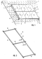
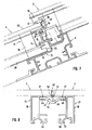
- Fig. 1 shows in the form of a schematic diagram arranged on a house roof 1 component group 2, comprising only exemplary six components 3, z.
- Example in the form of solar modules 4 comprising a plurality of solar cells serving for energy production.
- a frame structure 5 is provided, comprising two rails 6 running vertically here, which are fixed on the roof side via corresponding roof supports 7.
- Fastening means are arranged two support rails 8 on the rails 6 of the frame structure.
- the two support rails 8 are spaced and parallel to each other and traverse the rails 6 horizontally. They are part of a fastening device for the solar modules 4, which will be discussed in more detail below, which in turn are attached to the support rails 8 via suitable profile elements and retaining elements.
- suitable profile elements and retaining elements are suitable profile elements and retaining elements.
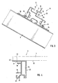
- Fig. 2 shows in an improved view of the frame structure 5 with the rails 6 and arranged thereon, usually screwed support profile rails 8, of which three are shown in the example shown.
- support profile rails 8 are used to attach a component 3, so each of a solar module, so that, based on such a solar module, each one support rail, the first support rail and the other support rail represents the second support rail.
- the supporting rails are all made the same
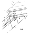
- Fig. 3 shows a sectional view through such a support profile 8.
- two vertically juxtaposed components 3 or 4 solar modules as this, starting from the example according to Fig.
- each support rail 8 in the central support rail 8 is the case, two mounting areas are formed on each support rail 8, a first mounting portion 9 consisting of a here T-shaped, ie both sides undercut groove 10 together with a support surface 11 and a limiting this stop 12, and a second Fastening region 13 in the form of an open towards the side, substantially C-shaped in cross-section receiving groove 14 having a lower support leg 15 and an upper leg 16 and a groove bottom 17.
- the two attachment areas 9 and 13 are obviously offset in height, the attachment area 9 is higher than the attachment area 13 Fig. 3
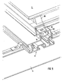
- the attachment of a support rail 8 is shown on a rail 6 of the base frame.
- two lateral T-slots 18 are provided, engage in the corresponding clamping plates 19, which in turn are fastened to the respective rail 6 via fastening screws, not shown.
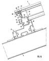
- Fig. 4 shows a partial view of a component 3, here a solar module 4 in the region of one of its edges, which may be either a side edge or the upper or lower edge of the component.
- a profile element 21 is arranged, usually glued, for which purpose the profile element 21 has a flat upper holding leg 22.
- a stiffening element eg of metal
- a stiffening element extending over the length of the profile element, which is preferably a rail, can be arranged.
- a first profile element 21 in the form of an over the entire vertical length of the solar cell module 4 extending rail 28 are arranged in the example shown.
- a not shown in detail, also designed as a profile rail profile element is disposed on the horizontal side 29.
- Both rails 28 are connected via a profile connector 30, which continues the respective profile rail form, and which also forms a profile element 21.
- the profile connector 30 as well as the horizontally extending, not shown profiled rail each have a profile section 23 which abuts against the stop web 12 of the first mounting portion 9. This limits the movement of the solar module, which is inclined at the mounting position downwards.
- a holding element 31 For fixing a holding element 31 is used, see Fig. 6 , a lower T-shaped hook portion 32, to which a longitudinal leg 33 connects, on which in turn a transverse leg 34 is arranged, the two lateral Holding portions 35 forms. Furthermore, two lateral stops 36 are provided.
- the holding element 31 which is flat in the region of its longitudinal limb, that is to say formed like a sheet with a thickness of 2-5 mm, will now be described in relation to FIGS Fig. 5 and 6 rotated by 90 ° position with the hook portion 32 inserted from above into the groove 10 and then by 90 ° in the in the Fig. 5 . 6 rotated position shown. Then, the hook portion 31 is pushed against the solar module 4 until the two stops 36 abut against the lower leg 25 of the profile section 23 of the profile connector 30, wherein in this position then a holding portion 35 has the holding web 24 overlapped surface, so that in connection with the hook portion 32 a clamping overlap is realized, which prevents lifting of the solar module.
- the design of the holding element 31, in particular the length of the stops 36, is dimensioned such that the two longitudinal narrow edge projections 37 of the adjacent profile elements 21 which protrude laterally by approximately 1 to 2 mm and prevent the glass edges of the module glass plates from contacting one another can abut, are only minimally spaced from each other, or directly adjacent to each other.
- Fig. 5 and 6 show the fixation of the lower edge of the component
- Fig. 7 the fixation of the upper edge of the component.
- Below the solar module 4 is also in the region of the upper edge a not shown here, parallel to the edge edge member 38 extending profile element 21 arranged in the form of a rail 28, which in turn via a profile connector 30, which in turn is a profile element 21, is connected to the vertically extending rail 28.
- the lower edge of the profile connector 30 and the horizontally extending rail 28 is now placed with the respective profile sections 23 on the support leg 15 of the second mounting portion 13 and then pushed a piece up until the profile section 23 in the C shaped receiving groove 14 is received and is overlapped by the legs 16.
- the lower component edge is placed on the first mounting portion 9 of the underlying support rail 8 and guided against the stop 12, as with respect to the Fig. 5 and 6 described. In any case, however, remains the profile section 23 of the profile connector 30 and the horizontally extending rail 28 in the C-shaped receiving groove 14, so that here is a backup against unintentional lifting is given. A further fixation in the region of the upper edge of the component does not take place, only against a horizontal displacement, as will be discussed below.
- a sealing element 39 is arranged, which extends over the entire horizontal width. It is arranged on the horizontally extending profile elements, ie the profile connector 30 and the horizontally extending, not shown rail 28. The fixation takes place in the groove 27, which serves as a clamping groove.
- the sealing element 39 has a corresponding slot 40, via which a clamping portion 54 is formed, which is inserted into the clamping groove 27. Furthermore, a downwardly projecting sealing lip 41 and a sealing loop 42 is provided on the inside.
- the solar module 4 is pushed under the sealing element 39, wherein the sealing lip 41 is deformed and sealingly rests on the upper side 43 of the lower solar module 4. This is a line seal in horizontal Direction reached.
- the upper solar module 4 thus overlaps the lower solar module 4, so that a shingled, shingled arrangement results.
- the sealing loop 42 can be compressed via the solar module 4, so that there is also a line seal.
- Fig. 7 Furthermore, shows a profiled member 44, which, as will be discussed below, extending in the vertical direction below the transition slot between two adjacent solar modules 4, against the sealing loop 42.
- This profile member 44 can via a projection 45 (eg., An inserted Pin), which engages behind the stop web 12, be fixed.
- the profile component 44 serving for sealing between two profile elements 21, here for example two profile rails 28, of two adjacent solar modules 4 shows Fig. 8 .
- the profile component 44 for example plastic, has a cross-sectional groove shape. It serves to seal the possibly remaining gap between the components 48. About two side portions 46, it engages in the grooves 27 of the rail 28 a. Evidently, the recess 47 resulting from the channel shape is below the possibly very narrow gap 48 between the immediately adjacent side edges of the two solar modules 4 and the edge projections 37. Any moisture entering via this gap 48 collects in the recess 47 and runs, After the arrangement is inclined, down to where it can be removed.
- the recess 47 may open slightly above the solar module below (in this area, if necessary, the sealing element 39 would be interrupted).
- a sealing web 49 on the profile component 44, for example, of a soft plastic material which, in the assembly position in the gap 48, seals it.
- the fixing methods described allow two components or a component group arranged one above the other to be moved horizontally.
- the outermost right and leftmost component of a row in the region of its lower component edge and its upper component edge is firmly connected to the support rail 8, see Fig. 9 .
- a claw-like holding member 52 is provided, which engages over the vertical web 53 of the profile connector 30, which is provided at its lower end and the part of the local profile section 23, and a suitable fastening screw together with the sliding block, the holding member 52 is then anchored in the groove 10 which can also be used to build up an anti-theft device.
- profile connectors 30, which themselves form profile elements 21, in the corner region of a component it is also possible to cut the profile rails miter and to connect via an inside simple corner connector by pressing. A bottom frame frame is then formed from only four rails with the inner corner connectors.
Landscapes
- Engineering & Computer Science (AREA)
- Chemical & Material Sciences (AREA)
- Mechanical Engineering (AREA)
- Sustainable Development (AREA)
- Sustainable Energy (AREA)
- Thermal Sciences (AREA)
- Physics & Mathematics (AREA)
- Combustion & Propulsion (AREA)
- Life Sciences & Earth Sciences (AREA)
- General Engineering & Computer Science (AREA)
- Architecture (AREA)
- Civil Engineering (AREA)
- Structural Engineering (AREA)
- Photovoltaic Devices (AREA)
- Roof Covering Using Slabs Or Stiff Sheets (AREA)
Applications Claiming Priority (1)
| Application Number | Priority Date | Filing Date | Title |
|---|---|---|---|
| DE102007027997A DE102007027997B4 (de) | 2007-06-14 | 2007-06-14 | Befestigungseinrichtung für an einem Gestellaufbau anzuordnende flächige rahmenlose Bauteile, insbesondere Solarmodule |
Publications (3)
| Publication Number | Publication Date |
|---|---|
| EP2003405A2 true EP2003405A2 (fr) | 2008-12-17 |
| EP2003405A3 EP2003405A3 (fr) | 2012-07-18 |
| EP2003405B1 EP2003405B1 (fr) | 2014-01-01 |
Family
ID=39777080
Family Applications (1)
| Application Number | Title | Priority Date | Filing Date |
|---|---|---|---|
| EP08007003.0A Not-in-force EP2003405B1 (fr) | 2007-06-14 | 2008-04-09 | Dispositif de fixation pour des composants plats installés sur un bâti, en particulier pour des modules solaires |
Country Status (3)
| Country | Link |
|---|---|
| US (1) | US8104239B2 (fr) |
| EP (1) | EP2003405B1 (fr) |
| DE (1) | DE102007027997B4 (fr) |
Cited By (10)
| Publication number | Priority date | Publication date | Assignee | Title |
|---|---|---|---|---|
| WO2009137887A1 (fr) * | 2008-05-16 | 2009-11-19 | Kerryj Investment Pty Ltd | Système de montage |
| AU2009101302B4 (en) * | 2008-05-16 | 2010-07-15 | Kerryj Investment Pty Ltd | Mounting system |
| WO2011045185A3 (fr) * | 2009-10-12 | 2011-09-15 | Fischer Lichtsysteme Gmbh | Système de montage pour modules solaires et installation solaire équipée de ce système de montage |
| FR2972471A1 (fr) * | 2011-03-10 | 2012-09-14 | Centurywatt | Revetement d'un pan de toiture muni de panneaux photovoltaiques lamines ou bi-verre standard |
| WO2012143006A1 (fr) * | 2011-04-21 | 2012-10-26 | Fath Solar Group Holding Gmbh | Module solaire |
| ITVI20110185A1 (it) * | 2011-07-13 | 2013-01-14 | Aulusplan S R L | Assieme di pannelli solari |
| EP2546585A1 (fr) * | 2011-07-12 | 2013-01-16 | Mauro Pula | Système de panneaux intégré |
| EP2525167A3 (fr) * | 2011-05-20 | 2014-07-30 | Robert Bosch Gmbh | Dispositif de fixation pour au moins un collecteur solaire |
| EP2426432A3 (fr) * | 2010-09-01 | 2015-03-18 | Mounting Systems GmbH | Rail de profilé, élément de support et agencement de module solaire ainsi formé, notamment pour un montage transversal de modules solaires |
| FR3032263A1 (fr) * | 2015-02-04 | 2016-08-05 | Ciel Et Terre Int | Fixation panneau a entraxe reglable |
Families Citing this family (97)
| Publication number | Priority date | Publication date | Assignee | Title |
|---|---|---|---|---|
| US7434362B2 (en) * | 2001-07-20 | 2008-10-14 | Unirac, Inc. | System for removably and adjustably mounting a device on a surface |
| US9151056B2 (en) * | 2008-04-17 | 2015-10-06 | Konvin Associates, L.P. | Dual glazing panel system |
| FR2945609B1 (fr) * | 2009-05-12 | 2013-03-29 | Avancis Gmbh & Co Kg | Dispositif de fixation et procede de montage de modules solaires. |
| FR2951479B1 (fr) * | 2009-10-16 | 2014-01-17 | Wilson Coelho | Structure support de panneaux solaires pour toiture de batiment |
| US20110209422A1 (en) * | 2010-02-18 | 2011-09-01 | King Zachary A | Method and apparatus for mounting photovoltaic modules to shingled surfaces |
| US8595996B2 (en) * | 2010-02-26 | 2013-12-03 | General Electric Company | Photovoltaic framed module array mount utilizing asymmetric rail |
| US8495839B2 (en) * | 2010-04-01 | 2013-07-30 | Yanegijutsukenkyujo Co., Ltd. | Installation structure of solar cell module |
| US8984751B2 (en) * | 2010-05-17 | 2015-03-24 | Andrew R Ramos | Composite configurable system to support solar panels on geomembrane |
| US20110277296A1 (en) * | 2010-05-17 | 2011-11-17 | Ramos Andrew R | Composite system to support solar panels on polymer covers on landfills |
| FR2961300B1 (fr) * | 2010-06-14 | 2014-05-09 | Inst Rech Fondamentale En Technologies Solaires Irfts | Structure de solidarisation de panneaux photovoltaiques sur un bati |
| US9074796B2 (en) | 2010-09-30 | 2015-07-07 | Apollo Precision (Kunming) Yuanhong Limited | Photovoltaic module support clamp assembly |
| US9239173B2 (en) | 2010-09-30 | 2016-01-19 | Apollo Precision (Fujian) Limited | Photovoltaic module support with interface strips |
| US9182152B2 (en) | 2010-09-30 | 2015-11-10 | Apollo Precision (Fujian) Limited | Photovoltaic module support with cable clamps |
| CA2755588A1 (fr) * | 2010-10-20 | 2012-04-20 | D Three Enterprises, Llc | Pince de montage et de mise a la terre combinee |
| US8656658B2 (en) * | 2010-10-20 | 2014-02-25 | Miasole | Retainers for attaching photovoltaic modules to mounting structures |
| FR2968376A1 (fr) * | 2010-12-06 | 2012-06-08 | Auversun | Ensemble de joints adaptes pour assurer l'etancheite entre deux cadres de panneau photovoltaique se chevauchant partiellement et cadre equipe de tels joints |
| DE102011084556A1 (de) * | 2011-01-12 | 2012-07-12 | Mounting Systems Gmbh | Befestigungssystem zur Montage von Solarmodulen auf einem Trapezblech |
| CN103782510B (zh) * | 2011-02-22 | 2017-07-28 | 光城公司 | 光伏模块的枢转配合框架、系统和方法 |
| DE102011013147B4 (de) * | 2011-03-04 | 2020-07-02 | Hpf Gmbh | Solardach |
| US8601755B2 (en) * | 2011-03-28 | 2013-12-10 | 1541689 Ontario Inc. | Solar panel supports |
| US8776454B2 (en) | 2011-04-05 | 2014-07-15 | Michael Zuritis | Solar array support structure, mounting rail and method of installation thereof |
| JP5795909B2 (ja) * | 2011-08-31 | 2015-10-14 | 元旦ビューティ工業株式会社 | 太陽電池モジュールの接続構造、及び接続方法 |
| TWI425646B (zh) * | 2012-01-06 | 2014-02-01 | Au Optronics Corp | 光伏陣列系統、其光伏裝置及其光伏裝置的側框件 |
| US9316417B2 (en) * | 2012-06-29 | 2016-04-19 | Sunpower Corporation | Framing system for mounting solar collecting devices |
| JP2014103337A (ja) * | 2012-11-22 | 2014-06-05 | Honda Motor Co Ltd | 太陽電池モジュール |
| US10256765B2 (en) | 2013-06-13 | 2019-04-09 | Building Materials Investment Corporation | Roof integrated photovoltaic system |
| US9273885B2 (en) * | 2013-06-13 | 2016-03-01 | Building Materials Investment Corporation | Roof integrated photovoltaic system |
| US8938932B1 (en) * | 2013-12-13 | 2015-01-27 | Quality Product Llc | Rail-less roof mounting system |
| CN106232915A (zh) * | 2014-04-16 | 2016-12-14 | 控制与发展企业有限公司 | 包括夹紧到型材的遮盖板的遮盖物 |
| US9670672B2 (en) * | 2014-12-03 | 2017-06-06 | Aleksandar Stevanov | Roof panel system |
| US20170133529A1 (en) * | 2015-11-05 | 2017-05-11 | Solarworld Industries Sachsen Gmbh | Photovoltaic modules and method of manufacturing a photovoltaic module |
| US20190207555A1 (en) * | 2016-12-27 | 2019-07-04 | Hall Labs Llc | Solar shingle installation and interconnection system |
| US11012024B2 (en) * | 2018-07-03 | 2021-05-18 | Building Materials Investment Corporation | Roof integrated photovoltaic system with improved serviceability |
| US11894797B1 (en) * | 2019-06-06 | 2024-02-06 | Powershingle, Llc | Solar support structures and methods |
| MX2022006401A (es) | 2019-11-27 | 2022-10-27 | GAF Energy LLC | Módulo fotovoltaico integrado de techo con espaciador. |
| US11398795B2 (en) | 2019-12-20 | 2022-07-26 | GAF Energy LLC | Roof integrated photovoltaic system |
| CA3165505A1 (fr) | 2020-01-22 | 2021-07-29 | Nathan Peterson | Bardeaux de toiture photovoltaiques integres, procedes, systemes et kits associes |
| EP4107790A4 (fr) | 2020-02-18 | 2024-03-13 | Gaf Energy LLC | Module photovoltaïque à superstrat texturé conférant un aspect imitant un bardeau |
| EP4111507A4 (fr) | 2020-02-27 | 2024-03-27 | Gaf Energy LLC | Module photovoltaïque avec agent d'encapsulation diffusant la lumière fournissant un aspect imitant le bardeau |
| US11961928B2 (en) | 2020-02-27 | 2024-04-16 | GAF Energy LLC | Photovoltaic module with light-scattering encapsulant providing shingle-mimicking appearance |
| MX2022011753A (es) | 2020-03-30 | 2022-10-18 | Bmic Llc | Paneles de techo estructurales laminados interconectables. |
| WO2021207238A1 (fr) | 2020-04-09 | 2021-10-14 | GAF Energy LLC | Module photovoltaïque stratifié tridimensionnel |
| US11217715B2 (en) | 2020-04-30 | 2022-01-04 | GAF Energy LLC | Photovoltaic module frontsheet and backsheet |
| CA3176241A1 (fr) | 2020-05-13 | 2021-11-18 | GAF Energy LLC | Passe-cable electrique |
| CN115769383A (zh) | 2020-06-04 | 2023-03-07 | Gaf能源有限责任公司 | 光伏屋顶板及其安装方法 |
| WO2022020490A1 (fr) | 2020-07-22 | 2022-01-27 | GAF Energy LLC | Modules photovoltaïques |
| WO2022035473A1 (fr) | 2020-08-11 | 2022-02-17 | GAF Energy LLC | Système photovoltaïque monté sur le toit et procédé de transfert sans fil d'énergie électrique |
| CN116420231A (zh) | 2020-09-03 | 2023-07-11 | Gaf能源有限责任公司 | 建筑集成光伏系统 |
| US11545928B2 (en) | 2020-10-13 | 2023-01-03 | GAF Energy LLC | Solar roofing system |
| EP4229750A4 (fr) | 2020-10-14 | 2024-11-13 | Gaf Energy LLC | Appareil de montage pour modules photovoltaïques |
| US11454027B2 (en) | 2020-10-29 | 2022-09-27 | GAF Energy LLC | System of roofing and photovoltaic shingles and methods of installing same |
| MX2021013676A (es) | 2020-11-09 | 2022-05-10 | Bmic Llc | Paneles estructurales entrelazados de techumbre con paneles solares integrados. |
| US11486144B2 (en) | 2020-11-12 | 2022-11-01 | GAF Energy LLC | Roofing shingles with handles |
| WO2022103841A1 (fr) | 2020-11-13 | 2022-05-19 | GAF Energy LLC | Systèmes et procédés pour modules photovoltaïques |
| MX2023006559A (es) | 2020-12-02 | 2023-09-18 | GAF Energy LLC | Aletas escalonadas para tejas fotovoltáicas para techos. |
| CA3205363A1 (fr) | 2021-01-19 | 2022-07-28 | Thierry Nguyen | Caracteristiques de deversement d'eau pour bardeaux de toiture |
| MX2023009726A (es) | 2021-02-19 | 2023-11-09 | GAF Energy LLC | Módulo fotovoltaico para un techo con cinta de fibra continua. |
| US12568694B2 (en) | 2021-03-19 | 2026-03-03 | GAF Energy LLC | Photovoltaic module with a laminated potted printed circuit board |
| MX2023011156A (es) | 2021-03-29 | 2023-10-05 | GAF Energy LLC | Componentes electricos para sitemas fotovoltaicos. |
| CN112865693A (zh) * | 2021-03-30 | 2021-05-28 | 高邮市瑞久金属材料有限公司 | 一种双层结构长使用寿命的太阳能发电板用铝制边框 |
| DE102021111373A1 (de) * | 2021-05-03 | 2022-11-03 | Stobag Ag | Dachkonstruktion |
| MX2023013029A (es) | 2021-05-06 | 2023-11-16 | GAF Energy LLC | Modulo fotovoltaico con bordes perimetrales transparentes. |
| MX2023014362A (es) | 2021-06-02 | 2023-12-15 | GAF Energy LLC | Modulo fotovoltaico con encapsulante de dispersion de la luz que proporciona una apariencia que imita a las tejas. |
| US12009781B2 (en) | 2021-07-06 | 2024-06-11 | GAF Energy LLC | Jumper module for photovoltaic systems |
| US11512480B1 (en) | 2021-07-16 | 2022-11-29 | GAF Energy LLC | Roof material storage bracket |
| US11728759B2 (en) | 2021-09-01 | 2023-08-15 | GAF Energy LLC | Photovoltaic modules for commercial roofing |
| WO2023141566A1 (fr) | 2022-01-20 | 2023-07-27 | GAF Energy LLC | Bardeaux de toiture pour imiter l'aspect de modules photovoltaïques |
| US12013153B2 (en) | 2022-02-08 | 2024-06-18 | GAF Energy LLC | Building integrated photovoltaic system |
| US12209414B2 (en) | 2022-02-23 | 2025-01-28 | GAF Energy LLC | Roofing shingle and method of manufacturing same |
| WO2023173019A1 (fr) | 2022-03-10 | 2023-09-14 | GAF Energy LLC | Encapsulant et feuille arrière combinés pour modules photovoltaïques |
| US12199550B2 (en) | 2022-04-08 | 2025-01-14 | GAF Energy LLC | Low profile connector for solar roofing systems |
| CA3257758A1 (fr) | 2022-06-06 | 2023-12-14 | GAF Energy LLC | Indicateurs de composants actifs pour systèmes photovoltaïques |
| US12325996B2 (en) | 2022-07-15 | 2025-06-10 | GAF Energy LLC | Solar roofing system with fiber composite roofing shingles |
| US12145348B2 (en) | 2022-08-24 | 2024-11-19 | GAF Energy LLC | System for forming a roofing membrane, and associated method |
| EP4581684A1 (fr) | 2022-08-29 | 2025-07-09 | Gaf Energy LLC | Modules photovoltaïques à couches décalées |
| US12034089B2 (en) | 2022-09-01 | 2024-07-09 | GAF Energy LLC | Anti-reflective photovoltaic shingles and related methods |
| WO2024059462A1 (fr) | 2022-09-13 | 2024-03-21 | GAF Energy LLC | Système de toiture à capteurs et procédé associé |
| US12015374B2 (en) | 2022-09-26 | 2024-06-18 | GAF Energy LLC | Photovoltaic modules integrated with building siding and fencing |
| WO2024073498A1 (fr) | 2022-09-29 | 2024-04-04 | GAF Energy LLC | Module de raccordement avec manchon |
| US12031332B2 (en) | 2022-10-25 | 2024-07-09 | GAF Energy LLC | Roofing materials and related methods |
| US12231075B2 (en) | 2022-10-27 | 2025-02-18 | GAF Energy LLC | Building integrated photovoltaic systems |
| US12413183B2 (en) | 2022-11-15 | 2025-09-09 | GAF Energy LLC | Electrical cable passthrough for photovoltaic systems |
| US11811361B1 (en) | 2022-12-14 | 2023-11-07 | GAF Energy LLC | Rapid shutdown device for photovoltaic modules |
| US12355390B1 (en) | 2023-02-03 | 2025-07-08 | GAF Energy LLC | Solar shingle and associated roofing system and method |
| US12445089B2 (en) | 2023-02-03 | 2025-10-14 | GAF Energy LLC | Photovoltaic module, and associated kit, system, and method |
| US12413174B2 (en) | 2023-02-21 | 2025-09-09 | GAF Energy LLC | Roofing system including photovoltaic module wireway cover, and associated method |
| CA3229888A1 (en) | 2023-02-23 | 2025-04-25 | GAF Energy LLC | Photovoltaic shingles with multi-module power electronics |
| US12506440B2 (en) | 2023-02-28 | 2025-12-23 | GAF Energy LLC | Photovoltaic modules with energy storage components |
| CA3231973A1 (en) | 2023-03-14 | 2025-06-26 | GAF Energy LLC | Integrated cell and circuit interconnection |
| US12009782B1 (en) | 2023-04-04 | 2024-06-11 | GAF Energy LLC | Photovoltaic systems with wireways |
| US12413177B2 (en) | 2023-08-31 | 2025-09-09 | GAF Energy LLC | Photovoltaic modules and roofing shingles with nail zones |
| US12451838B1 (en) | 2023-10-06 | 2025-10-21 | GAF Energy LLC | Failsafe functionality for photovoltaic modules |
| WO2025090902A1 (fr) | 2023-10-26 | 2025-05-01 | GAF Energy LLC | Systèmes de toiture à protection contre l'entrée d'eau |
| WO2025122742A1 (fr) | 2023-12-05 | 2025-06-12 | GAF Energy LLC | Système de toiture pour la prévention de la déformation d'un bardeau de toiture |
| DE202024100335U1 (de) | 2024-01-23 | 2024-02-02 | Pentagon, Warenhandels- und Verlagsgesellschaft mbH | Montagesystem für Photovoltaik-Module und andere flächige Elemente |
| WO2025217150A1 (fr) | 2024-04-10 | 2025-10-16 | GAF Energy LLC | Bardeaux de toiture à structure ignifuge |
| US12540474B2 (en) | 2024-07-22 | 2026-02-03 | GAF Energy LLC | Electrically grounding metal roofing shingles with photovoltaic systems |
Citations (2)
| Publication number | Priority date | Publication date | Assignee | Title |
|---|---|---|---|---|
| DE102004044103A1 (de) | 2003-09-17 | 2005-04-21 | Michael Buechele | Einrichtung zur Befestigung von Solarmodulen an Befestigungsprofilen |
| DE102006053831A1 (de) | 2006-11-14 | 2008-05-15 | Fath Gmbh | Befestigungseinrichtung für an einem Gestellaufbau anzuordnende Rahmenbauteile, insbesondere Solarmodule |
Family Cites Families (25)
| Publication number | Priority date | Publication date | Assignee | Title |
|---|---|---|---|---|
| DE3611542A1 (de) * | 1986-04-05 | 1987-10-08 | Remscheid Volksbank | Solarmodul |
| EP0531869B1 (fr) | 1991-09-11 | 1997-01-08 | SIEMENS SOLAR GmbH | Pince de montage |
| ATE187789T1 (de) * | 1993-04-22 | 2000-01-15 | Richard Waddington | Verbessertes schindel-dachaufbau |
| US5460660A (en) | 1993-07-21 | 1995-10-24 | Photon Energy, Inc. | Apparatus for encapsulating a photovoltaic module |
| US6111189A (en) * | 1998-07-28 | 2000-08-29 | Bp Solarex | Photovoltaic module framing system with integral electrical raceways |
| DE19934073B4 (de) * | 1999-07-19 | 2005-08-25 | Regen Energiesysteme Gmbh | Vorrichtung zur Befestigung von Solarmodulen |
| US7012188B2 (en) * | 2000-04-04 | 2006-03-14 | Peter Stuart Erling | Framing system for solar panels |
| ATE249605T1 (de) * | 2000-04-10 | 2003-09-15 | Soltop Schuppisser Ag | Modulartiger solarkollektor |
| FR2809431B1 (fr) * | 2000-05-24 | 2002-08-30 | Novitech | Systeme de couverture a rangees de tuiles superposees |
| US20020112435A1 (en) * | 2000-07-03 | 2002-08-22 | Hartman Paul H. | Demand side management structures |
| DE10216899A1 (de) * | 2002-04-17 | 2003-11-06 | Volker Schulte | Sonnenkollektor |
| DE10224437A1 (de) * | 2002-06-01 | 2003-12-11 | Hans Joachim Damm | Befestigungsvorrichtung für ein Solarkollektor-Modul |
| US20040000334A1 (en) * | 2002-06-27 | 2004-01-01 | Astropower, Inc. | Photovoltaic tiles, roofing system, and method of constructing roof |
| JP2004150137A (ja) * | 2002-10-30 | 2004-05-27 | Kyocera Corp | 屋根設置体の固定構造 |
| US20040216399A1 (en) * | 2003-01-30 | 2004-11-04 | Kyocera Corporation | Fixing apparatus |
| US20040154655A1 (en) * | 2003-02-12 | 2004-08-12 | Sharp Kabushiki Kaisha | Attaching structural unit used for installing quadrangular solar-battery module onto slanted roof |
| US7600349B2 (en) * | 2003-02-26 | 2009-10-13 | Unirac, Inc. | Low profile mounting system |
| US20040221886A1 (en) * | 2003-02-26 | 2004-11-11 | Kyocera Corporation | Solar cell module and solar cell array using same |
| JP4056419B2 (ja) * | 2003-03-31 | 2008-03-05 | シャープ株式会社 | 太陽電池ユニットおよびその屋根取り付け方法 |
| US6959517B2 (en) * | 2003-05-09 | 2005-11-01 | First Solar, Llc | Photovoltaic panel mounting bracket |
| DE202004015811U1 (de) * | 2004-10-13 | 2004-12-16 | Bbt Thermotechnik Gmbh | Befestigungsvorrichtung für mindestens einen Sonnenkollektor |
| DE202004019259U1 (de) * | 2004-12-12 | 2005-07-14 | Schmidt-Cornelius, Hans-Otto | Solar-Steckgestell-Element zur Montage von Solar-Photovoltaikmodulen |
| AT501455B1 (de) * | 2005-02-21 | 2006-11-15 | Lechthaler Andreas | Traggestell für plattenförmige solarzellen- oder sonnenkollektor-module |
| JP4684874B2 (ja) | 2005-12-13 | 2011-05-18 | 株式会社屋根技術研究所 | 太陽電池モジュール枠体 |
| DE202006018586U1 (de) * | 2006-12-06 | 2007-03-08 | Kaack, Peter | Anordnung zum Montieren von Solarmodulen |
-
2007
- 2007-06-14 DE DE102007027997A patent/DE102007027997B4/de not_active Expired - Fee Related
-
2008
- 2008-04-09 EP EP08007003.0A patent/EP2003405B1/fr not_active Not-in-force
- 2008-04-23 US US12/148,849 patent/US8104239B2/en not_active Expired - Fee Related
Patent Citations (2)
| Publication number | Priority date | Publication date | Assignee | Title |
|---|---|---|---|---|
| DE102004044103A1 (de) | 2003-09-17 | 2005-04-21 | Michael Buechele | Einrichtung zur Befestigung von Solarmodulen an Befestigungsprofilen |
| DE102006053831A1 (de) | 2006-11-14 | 2008-05-15 | Fath Gmbh | Befestigungseinrichtung für an einem Gestellaufbau anzuordnende Rahmenbauteile, insbesondere Solarmodule |
Cited By (13)
| Publication number | Priority date | Publication date | Assignee | Title |
|---|---|---|---|---|
| US8640401B2 (en) | 2008-05-16 | 2014-02-04 | Kerry J Investments Pty Ltd. | Photovoltaic panel mounting system |
| AU2009101302B4 (en) * | 2008-05-16 | 2010-07-15 | Kerryj Investment Pty Ltd | Mounting system |
| WO2009137887A1 (fr) * | 2008-05-16 | 2009-11-19 | Kerryj Investment Pty Ltd | Système de montage |
| WO2011045185A3 (fr) * | 2009-10-12 | 2011-09-15 | Fischer Lichtsysteme Gmbh | Système de montage pour modules solaires et installation solaire équipée de ce système de montage |
| EP2426432A3 (fr) * | 2010-09-01 | 2015-03-18 | Mounting Systems GmbH | Rail de profilé, élément de support et agencement de module solaire ainsi formé, notamment pour un montage transversal de modules solaires |
| FR2972471A1 (fr) * | 2011-03-10 | 2012-09-14 | Centurywatt | Revetement d'un pan de toiture muni de panneaux photovoltaiques lamines ou bi-verre standard |
| WO2012120208A3 (fr) * | 2011-03-10 | 2012-11-15 | Centurywatt | Revêtement d'un pan de toiture muni de panneaux photovoltaïques lamines ou bi-verre standard |
| WO2012143006A1 (fr) * | 2011-04-21 | 2012-10-26 | Fath Solar Group Holding Gmbh | Module solaire |
| EP2525167A3 (fr) * | 2011-05-20 | 2014-07-30 | Robert Bosch Gmbh | Dispositif de fixation pour au moins un collecteur solaire |
| EP2546585A1 (fr) * | 2011-07-12 | 2013-01-16 | Mauro Pula | Système de panneaux intégré |
| ITVI20110185A1 (it) * | 2011-07-13 | 2013-01-14 | Aulusplan S R L | Assieme di pannelli solari |
| FR3032263A1 (fr) * | 2015-02-04 | 2016-08-05 | Ciel Et Terre Int | Fixation panneau a entraxe reglable |
| WO2016124858A1 (fr) * | 2015-02-04 | 2016-08-11 | Ciel Et Terre International | Dispositif de fixation de panneau solaire |
Also Published As
| Publication number | Publication date |
|---|---|
| US8104239B2 (en) | 2012-01-31 |
| DE102007027997B4 (de) | 2012-12-06 |
| US20080315061A1 (en) | 2008-12-25 |
| DE102007027997A1 (de) | 2008-12-18 |
| EP2003405B1 (fr) | 2014-01-01 |
| EP2003405A3 (fr) | 2012-07-18 |
Similar Documents
| Publication | Publication Date | Title |
|---|---|---|
| EP2003405B1 (fr) | Dispositif de fixation pour des composants plats installés sur un bâti, en particulier pour des modules solaires | |
| DE102007033323B4 (de) | Befestigungseinrichtung für an einem Gestellaufbau anzuordnende flächige Bauteile, insbesondere Solarmodule | |
| DE102007056600B4 (de) | Photovoltaikanlage mit einer Matrix aus rahmenlosen Solarmodulen | |
| EP2691704B1 (fr) | Agencement avec modules de fixation destinés à fixer des modules solaires | |
| DE102004026786A1 (de) | Halteprofil und Montagesystem für ungerahmte Solarmodule | |
| DE102007018212B4 (de) | Befestigungseinrichtung für an einem Gestellaufbau anzuordnende Rahmenbauteile, insbesondere Solarmodule | |
| DE202011003490U1 (de) | Halteklammer | |
| EP2423622B1 (fr) | Dispositif de fixation avec éléments de montage et rail de support | |
| EP2982812B1 (fr) | Systeme de fixation d'elements de façades en forme de plaques, procede de montage d'elements de façades en forme de plaque et façade | |
| DE9407701U1 (de) | Bausatz zur Halterung einer aus Platten, insbesondere Glasplatten o.dgl. zusammensetzbaren Fassade oder Dacheindeckung | |
| AT512032B1 (de) | Anordnung zur befestigung von platten | |
| DE102006053831B4 (de) | Befestigungseinrichtung für an einem Gestellaufbau anzuordnende Rahmenbauteile, insbesondere Solarmodule | |
| AT511006B1 (de) | Montagesystem und verfahren zur befestigung von solarmodulrahmen auf darunterliegende primärschienen | |
| DE202021104820U1 (de) | Befestigungsvorrichtung zur Befestigung eines einen Teil eines Daches eines Gebäudes bildenden Photovoltaikmoduls am Gebäude und Verbindungsvorrichtungen zur Verbindung solcher Photovoltaikmodule miteinander | |
| DE8418908U1 (de) | Haltevorrichtung mit halterung fuer sonnenkollektoren | |
| EP2458302B1 (fr) | Elément de liaison et dispositif de fixation de modules solaires | |
| EP1647649A2 (fr) | Système de fixation de façades | |
| AT517212B1 (de) | Montagesystem für Solarmodul | |
| DE9102071U1 (de) | Befestigungsvorrichtung | |
| DE29501224U1 (de) | Unterkonstruktion für mit Dachplatten eingedeckte Steildächer | |
| EP2896909B1 (fr) | Système de montage en toiture de modules solaires | |
| WO2012104423A1 (fr) | Élément de maintien réglable pour toits à profil trapézoïdal | |
| EP2345086A2 (fr) | Adaptateur conçu pour la fixation de modules solaires, modules solaires fixés à l'aide d'adaptateurs et procédé de fixation de modules solaires | |
| AT506369A1 (de) | Spannschiene für eine membrane einer membranpresse | |
| WO2012168389A1 (fr) | Ensemble cadre et ensemble module solaire |
Legal Events
| Date | Code | Title | Description |
|---|---|---|---|
| PUAI | Public reference made under article 153(3) epc to a published international application that has entered the european phase |
Free format text: ORIGINAL CODE: 0009012 |
|
| AK | Designated contracting states |
Kind code of ref document: A2 Designated state(s): AT BE BG CH CY CZ DE DK EE ES FI FR GB GR HR HU IE IS IT LI LT LU LV MC MT NL NO PL PT RO SE SI SK TR |
|
| AX | Request for extension of the european patent |
Extension state: AL BA MK RS |
|
| PUAL | Search report despatched |
Free format text: ORIGINAL CODE: 0009013 |
|
| AK | Designated contracting states |
Kind code of ref document: A3 Designated state(s): AT BE BG CH CY CZ DE DK EE ES FI FR GB GR HR HU IE IS IT LI LT LU LV MC MT NL NO PL PT RO SE SI SK TR |
|
| AX | Request for extension of the european patent |
Extension state: AL BA MK RS |
|
| RIC1 | Information provided on ipc code assigned before grant |
Ipc: F24J 2/46 20060101ALI20120613BHEP Ipc: H01L 31/042 20060101ALI20120613BHEP Ipc: H01L 31/048 20060101ALI20120613BHEP Ipc: F24J 2/52 20060101AFI20120613BHEP |
|
| 17P | Request for examination filed |
Effective date: 20120913 |
|
| AKX | Designation fees paid |
Designated state(s): AT BE BG CH CY CZ DE DK EE ES FI FR GB GR HR HU IE IS IT LI LT LU LV MC MT NL NO PL PT RO SE SI SK TR |
|
| 17Q | First examination report despatched |
Effective date: 20130306 |
|
| GRAP | Despatch of communication of intention to grant a patent |
Free format text: ORIGINAL CODE: EPIDOSNIGR1 |
|
| RAP1 | Party data changed (applicant data changed or rights of an application transferred) |
Owner name: FATH GMBH |
|
| INTG | Intention to grant announced |
Effective date: 20131017 |
|
| GRAS | Grant fee paid |
Free format text: ORIGINAL CODE: EPIDOSNIGR3 |
|
| GRAA | (expected) grant |
Free format text: ORIGINAL CODE: 0009210 |
|
| AK | Designated contracting states |
Kind code of ref document: B1 Designated state(s): AT BE BG CH CY CZ DE DK EE ES FI FR GB GR HR HU IE IS IT LI LT LU LV MC MT NL NO PL PT RO SE SI SK TR |
|
| REG | Reference to a national code |
Ref country code: GB Ref legal event code: FG4D Free format text: NOT ENGLISH |
|
| REG | Reference to a national code |
Ref country code: CH Ref legal event code: EP |
|
| REG | Reference to a national code |
Ref country code: IE Ref legal event code: FG4D Free format text: LANGUAGE OF EP DOCUMENT: GERMAN |
|
| REG | Reference to a national code |
Ref country code: CH Ref legal event code: NV Representative=s name: ISLER AND PEDRAZZINI AG, CH |
|
| REG | Reference to a national code |
Ref country code: DE Ref legal event code: R096 Ref document number: 502008011139 Country of ref document: DE Effective date: 20140213 |
|
| REG | Reference to a national code |
Ref country code: AT Ref legal event code: REF Ref document number: 647775 Country of ref document: AT Kind code of ref document: T Effective date: 20140215 |
|
| REG | Reference to a national code |
Ref country code: NL Ref legal event code: T3 |
|
| PGFP | Annual fee paid to national office [announced via postgrant information from national office to epo] |
Ref country code: IE Payment date: 20140326 Year of fee payment: 7 |
|
| PGFP | Annual fee paid to national office [announced via postgrant information from national office to epo] |
Ref country code: LU Payment date: 20140403 Year of fee payment: 7 |
|
| REG | Reference to a national code |
Ref country code: LT Ref legal event code: MG4D |
|
| PG25 | Lapsed in a contracting state [announced via postgrant information from national office to epo] |
Ref country code: IS Free format text: LAPSE BECAUSE OF FAILURE TO SUBMIT A TRANSLATION OF THE DESCRIPTION OR TO PAY THE FEE WITHIN THE PRESCRIBED TIME-LIMIT Effective date: 20140501 Ref country code: LT Free format text: LAPSE BECAUSE OF FAILURE TO SUBMIT A TRANSLATION OF THE DESCRIPTION OR TO PAY THE FEE WITHIN THE PRESCRIBED TIME-LIMIT Effective date: 20140101 |
|
| PGFP | Annual fee paid to national office [announced via postgrant information from national office to epo] |
Ref country code: GB Payment date: 20140417 Year of fee payment: 7 |
|
| PG25 | Lapsed in a contracting state [announced via postgrant information from national office to epo] |
Ref country code: ES Free format text: LAPSE BECAUSE OF FAILURE TO SUBMIT A TRANSLATION OF THE DESCRIPTION OR TO PAY THE FEE WITHIN THE PRESCRIBED TIME-LIMIT Effective date: 20140101 Ref country code: PT Free format text: LAPSE BECAUSE OF FAILURE TO SUBMIT A TRANSLATION OF THE DESCRIPTION OR TO PAY THE FEE WITHIN THE PRESCRIBED TIME-LIMIT Effective date: 20140502 Ref country code: FI Free format text: LAPSE BECAUSE OF FAILURE TO SUBMIT A TRANSLATION OF THE DESCRIPTION OR TO PAY THE FEE WITHIN THE PRESCRIBED TIME-LIMIT Effective date: 20140101 Ref country code: SE Free format text: LAPSE BECAUSE OF FAILURE TO SUBMIT A TRANSLATION OF THE DESCRIPTION OR TO PAY THE FEE WITHIN THE PRESCRIBED TIME-LIMIT Effective date: 20140101 Ref country code: CY Free format text: LAPSE BECAUSE OF FAILURE TO SUBMIT A TRANSLATION OF THE DESCRIPTION OR TO PAY THE FEE WITHIN THE PRESCRIBED TIME-LIMIT Effective date: 20140101 |
|
| PGFP | Annual fee paid to national office [announced via postgrant information from national office to epo] |
Ref country code: FR Payment date: 20140430 Year of fee payment: 7 Ref country code: AT Payment date: 20140408 Year of fee payment: 7 Ref country code: CH Payment date: 20140415 Year of fee payment: 7 |
|
| PG25 | Lapsed in a contracting state [announced via postgrant information from national office to epo] |
Ref country code: LV Free format text: LAPSE BECAUSE OF FAILURE TO SUBMIT A TRANSLATION OF THE DESCRIPTION OR TO PAY THE FEE WITHIN THE PRESCRIBED TIME-LIMIT Effective date: 20140101 Ref country code: HR Free format text: LAPSE BECAUSE OF FAILURE TO SUBMIT A TRANSLATION OF THE DESCRIPTION OR TO PAY THE FEE WITHIN THE PRESCRIBED TIME-LIMIT Effective date: 20140101 |
|
| PGFP | Annual fee paid to national office [announced via postgrant information from national office to epo] |
Ref country code: BE Payment date: 20140417 Year of fee payment: 7 |
|
| REG | Reference to a national code |
Ref country code: DE Ref legal event code: R097 Ref document number: 502008011139 Country of ref document: DE |
|
| PG25 | Lapsed in a contracting state [announced via postgrant information from national office to epo] |
Ref country code: RO Free format text: LAPSE BECAUSE OF FAILURE TO SUBMIT A TRANSLATION OF THE DESCRIPTION OR TO PAY THE FEE WITHIN THE PRESCRIBED TIME-LIMIT Effective date: 20140101 Ref country code: EE Free format text: LAPSE BECAUSE OF FAILURE TO SUBMIT A TRANSLATION OF THE DESCRIPTION OR TO PAY THE FEE WITHIN THE PRESCRIBED TIME-LIMIT Effective date: 20140101 Ref country code: DK Free format text: LAPSE BECAUSE OF FAILURE TO SUBMIT A TRANSLATION OF THE DESCRIPTION OR TO PAY THE FEE WITHIN THE PRESCRIBED TIME-LIMIT Effective date: 20140101 Ref country code: CZ Free format text: LAPSE BECAUSE OF FAILURE TO SUBMIT A TRANSLATION OF THE DESCRIPTION OR TO PAY THE FEE WITHIN THE PRESCRIBED TIME-LIMIT Effective date: 20140101 |
|
| PLBE | No opposition filed within time limit |
Free format text: ORIGINAL CODE: 0009261 |
|
| STAA | Information on the status of an ep patent application or granted ep patent |
Free format text: STATUS: NO OPPOSITION FILED WITHIN TIME LIMIT |
|
| PG25 | Lapsed in a contracting state [announced via postgrant information from national office to epo] |
Ref country code: PL Free format text: LAPSE BECAUSE OF FAILURE TO SUBMIT A TRANSLATION OF THE DESCRIPTION OR TO PAY THE FEE WITHIN THE PRESCRIBED TIME-LIMIT Effective date: 20140101 Ref country code: SK Free format text: LAPSE BECAUSE OF FAILURE TO SUBMIT A TRANSLATION OF THE DESCRIPTION OR TO PAY THE FEE WITHIN THE PRESCRIBED TIME-LIMIT Effective date: 20140101 Ref country code: MC Free format text: LAPSE BECAUSE OF FAILURE TO SUBMIT A TRANSLATION OF THE DESCRIPTION OR TO PAY THE FEE WITHIN THE PRESCRIBED TIME-LIMIT Effective date: 20140101 |
|
| 26N | No opposition filed |
Effective date: 20141002 |
|
| REG | Reference to a national code |
Ref country code: DE Ref legal event code: R097 Ref document number: 502008011139 Country of ref document: DE Effective date: 20141002 |
|
| PG25 | Lapsed in a contracting state [announced via postgrant information from national office to epo] |
Ref country code: SI Free format text: LAPSE BECAUSE OF FAILURE TO SUBMIT A TRANSLATION OF THE DESCRIPTION OR TO PAY THE FEE WITHIN THE PRESCRIBED TIME-LIMIT Effective date: 20140101 |
|
| PGFP | Annual fee paid to national office [announced via postgrant information from national office to epo] |
Ref country code: NL Payment date: 20150422 Year of fee payment: 8 |
|
| PGFP | Annual fee paid to national office [announced via postgrant information from national office to epo] |
Ref country code: DE Payment date: 20150420 Year of fee payment: 8 |
|
| REG | Reference to a national code |
Ref country code: DE Ref legal event code: R082 Ref document number: 502008011139 Country of ref document: DE Representative=s name: SCHNEIDER, ANDREAS, DIPL.-PHYS., DE |
|
| PG25 | Lapsed in a contracting state [announced via postgrant information from national office to epo] |
Ref country code: LU Free format text: LAPSE BECAUSE OF NON-PAYMENT OF DUE FEES Effective date: 20150409 |
|
| REG | Reference to a national code |
Ref country code: CH Ref legal event code: PL |
|
| REG | Reference to a national code |
Ref country code: AT Ref legal event code: MM01 Ref document number: 647775 Country of ref document: AT Kind code of ref document: T Effective date: 20150409 |
|
| GBPC | Gb: european patent ceased through non-payment of renewal fee |
Effective date: 20150409 |
|
| REG | Reference to a national code |
Ref country code: IE Ref legal event code: MM4A |
|
| PG25 | Lapsed in a contracting state [announced via postgrant information from national office to epo] |
Ref country code: LI Free format text: LAPSE BECAUSE OF NON-PAYMENT OF DUE FEES Effective date: 20150430 Ref country code: GB Free format text: LAPSE BECAUSE OF NON-PAYMENT OF DUE FEES Effective date: 20150409 Ref country code: CH Free format text: LAPSE BECAUSE OF NON-PAYMENT OF DUE FEES Effective date: 20150430 |
|
| REG | Reference to a national code |
Ref country code: FR Ref legal event code: ST Effective date: 20151231 |
|
| PG25 | Lapsed in a contracting state [announced via postgrant information from national office to epo] |
Ref country code: AT Free format text: LAPSE BECAUSE OF NON-PAYMENT OF DUE FEES Effective date: 20150409 Ref country code: FR Free format text: LAPSE BECAUSE OF NON-PAYMENT OF DUE FEES Effective date: 20150430 |
|
| PG25 | Lapsed in a contracting state [announced via postgrant information from national office to epo] |
Ref country code: MT Free format text: LAPSE BECAUSE OF FAILURE TO SUBMIT A TRANSLATION OF THE DESCRIPTION OR TO PAY THE FEE WITHIN THE PRESCRIBED TIME-LIMIT Effective date: 20140101 |
|
| PG25 | Lapsed in a contracting state [announced via postgrant information from national office to epo] |
Ref country code: NO Free format text: LAPSE BECAUSE OF FAILURE TO SUBMIT A TRANSLATION OF THE DESCRIPTION OR TO PAY THE FEE WITHIN THE PRESCRIBED TIME-LIMIT Effective date: 20140401 Ref country code: IE Free format text: LAPSE BECAUSE OF NON-PAYMENT OF DUE FEES Effective date: 20150409 |
|
| PG25 | Lapsed in a contracting state [announced via postgrant information from national office to epo] |
Ref country code: BG Free format text: LAPSE BECAUSE OF FAILURE TO SUBMIT A TRANSLATION OF THE DESCRIPTION OR TO PAY THE FEE WITHIN THE PRESCRIBED TIME-LIMIT Effective date: 20140101 |
|
| PG25 | Lapsed in a contracting state [announced via postgrant information from national office to epo] |
Ref country code: GR Free format text: LAPSE BECAUSE OF FAILURE TO SUBMIT A TRANSLATION OF THE DESCRIPTION OR TO PAY THE FEE WITHIN THE PRESCRIBED TIME-LIMIT Effective date: 20140402 |
|
| PG25 | Lapsed in a contracting state [announced via postgrant information from national office to epo] |
Ref country code: HU Free format text: LAPSE BECAUSE OF FAILURE TO SUBMIT A TRANSLATION OF THE DESCRIPTION OR TO PAY THE FEE WITHIN THE PRESCRIBED TIME-LIMIT; INVALID AB INITIO Effective date: 20080409 Ref country code: TR Free format text: LAPSE BECAUSE OF FAILURE TO SUBMIT A TRANSLATION OF THE DESCRIPTION OR TO PAY THE FEE WITHIN THE PRESCRIBED TIME-LIMIT Effective date: 20140101 |
|
| REG | Reference to a national code |
Ref country code: DE Ref legal event code: R119 Ref document number: 502008011139 Country of ref document: DE |
|
| REG | Reference to a national code |
Ref country code: NL Ref legal event code: MM Effective date: 20160501 |
|
| PG25 | Lapsed in a contracting state [announced via postgrant information from national office to epo] |
Ref country code: NL Free format text: LAPSE BECAUSE OF NON-PAYMENT OF DUE FEES Effective date: 20160501 Ref country code: DE Free format text: LAPSE BECAUSE OF NON-PAYMENT OF DUE FEES Effective date: 20161101 |
|
| PG25 | Lapsed in a contracting state [announced via postgrant information from national office to epo] |
Ref country code: BE Free format text: LAPSE BECAUSE OF NON-PAYMENT OF DUE FEES Effective date: 20150430 |
|
| PGFP | Annual fee paid to national office [announced via postgrant information from national office to epo] |
Ref country code: IT Payment date: 20170419 Year of fee payment: 10 |
|
| PG25 | Lapsed in a contracting state [announced via postgrant information from national office to epo] |
Ref country code: IT Free format text: LAPSE BECAUSE OF NON-PAYMENT OF DUE FEES Effective date: 20180409 |