EP2423622B1 - Dispositif de fixation avec éléments de montage et rail de support - Google Patents
Dispositif de fixation avec éléments de montage et rail de support Download PDFInfo
- Publication number
- EP2423622B1 EP2423622B1 EP11177666.2A EP11177666A EP2423622B1 EP 2423622 B1 EP2423622 B1 EP 2423622B1 EP 11177666 A EP11177666 A EP 11177666A EP 2423622 B1 EP2423622 B1 EP 2423622B1
- Authority
- EP
- European Patent Office
- Prior art keywords
- mounting
- fixing
- support
- base support
- support rail
- Prior art date
- Legal status (The legal status is an assumption and is not a legal conclusion. Google has not performed a legal analysis and makes no representation as to the accuracy of the status listed.)
- Active
Links
Images

Classifications
-
- A—HUMAN NECESSITIES
- A47—FURNITURE; DOMESTIC ARTICLES OR APPLIANCES; COFFEE MILLS; SPICE MILLS; SUCTION CLEANERS IN GENERAL
- A47H—FURNISHINGS FOR WINDOWS OR DOORS
- A47H1/00—Curtain suspension devices
- A47H1/10—Means for mounting curtain rods or rails
- A47H1/104—Means for mounting curtain rods or rails for mounting curtain rails
-
- F—MECHANICAL ENGINEERING; LIGHTING; HEATING; WEAPONS; BLASTING
- F24—HEATING; RANGES; VENTILATING
- F24S—SOLAR HEAT COLLECTORS; SOLAR HEAT SYSTEMS
- F24S25/00—Arrangement of stationary mountings or supports for solar heat collector modules
- F24S25/30—Arrangement of stationary mountings or supports for solar heat collector modules using elongate rigid mounting elements extending substantially along the supporting surface, e.g. for covering buildings with solar heat collectors
-
- F—MECHANICAL ENGINEERING; LIGHTING; HEATING; WEAPONS; BLASTING
- F24—HEATING; RANGES; VENTILATING
- F24S—SOLAR HEAT COLLECTORS; SOLAR HEAT SYSTEMS
- F24S25/00—Arrangement of stationary mountings or supports for solar heat collector modules
- F24S25/30—Arrangement of stationary mountings or supports for solar heat collector modules using elongate rigid mounting elements extending substantially along the supporting surface, e.g. for covering buildings with solar heat collectors
- F24S25/33—Arrangement of stationary mountings or supports for solar heat collector modules using elongate rigid mounting elements extending substantially along the supporting surface, e.g. for covering buildings with solar heat collectors forming substantially planar assemblies, e.g. of coplanar or stacked profiles
-
- F—MECHANICAL ENGINEERING; LIGHTING; HEATING; WEAPONS; BLASTING
- F24—HEATING; RANGES; VENTILATING
- F24S—SOLAR HEAT COLLECTORS; SOLAR HEAT SYSTEMS
- F24S25/00—Arrangement of stationary mountings or supports for solar heat collector modules
- F24S25/60—Fixation means, e.g. fasteners, specially adapted for supporting solar heat collector modules
- F24S25/61—Fixation means, e.g. fasteners, specially adapted for supporting solar heat collector modules for fixing to the ground or to building structures
-
- F—MECHANICAL ENGINEERING; LIGHTING; HEATING; WEAPONS; BLASTING
- F24—HEATING; RANGES; VENTILATING
- F24S—SOLAR HEAT COLLECTORS; SOLAR HEAT SYSTEMS
- F24S25/00—Arrangement of stationary mountings or supports for solar heat collector modules
- F24S25/60—Fixation means, e.g. fasteners, specially adapted for supporting solar heat collector modules
- F24S25/65—Fixation means, e.g. fasteners, specially adapted for supporting solar heat collector modules for coupling adjacent supporting elements, e.g. for connecting profiles together
-
- F—MECHANICAL ENGINEERING; LIGHTING; HEATING; WEAPONS; BLASTING
- F24—HEATING; RANGES; VENTILATING
- F24S—SOLAR HEAT COLLECTORS; SOLAR HEAT SYSTEMS
- F24S25/00—Arrangement of stationary mountings or supports for solar heat collector modules
- F24S25/70—Arrangement of stationary mountings or supports for solar heat collector modules with means for adjusting the final position or orientation of supporting elements in relation to each other or to a mounting surface; with means for compensating mounting tolerances
-
- F—MECHANICAL ENGINEERING; LIGHTING; HEATING; WEAPONS; BLASTING
- F24—HEATING; RANGES; VENTILATING
- F24S—SOLAR HEAT COLLECTORS; SOLAR HEAT SYSTEMS
- F24S25/00—Arrangement of stationary mountings or supports for solar heat collector modules
- F24S25/60—Fixation means, e.g. fasteners, specially adapted for supporting solar heat collector modules
- F24S2025/6007—Fixation means, e.g. fasteners, specially adapted for supporting solar heat collector modules by using form-fitting connection means, e.g. tongue and groove
-
- Y—GENERAL TAGGING OF NEW TECHNOLOGICAL DEVELOPMENTS; GENERAL TAGGING OF CROSS-SECTIONAL TECHNOLOGIES SPANNING OVER SEVERAL SECTIONS OF THE IPC; TECHNICAL SUBJECTS COVERED BY FORMER USPC CROSS-REFERENCE ART COLLECTIONS [XRACs] AND DIGESTS
- Y02—TECHNOLOGIES OR APPLICATIONS FOR MITIGATION OR ADAPTATION AGAINST CLIMATE CHANGE
- Y02E—REDUCTION OF GREENHOUSE GAS [GHG] EMISSIONS, RELATED TO ENERGY GENERATION, TRANSMISSION OR DISTRIBUTION
- Y02E10/00—Energy generation through renewable energy sources
- Y02E10/40—Solar thermal energy, e.g. solar towers
- Y02E10/47—Mountings or tracking
Definitions
- the invention relates to a fastening device comprising a mounting rail and U-shaped holder, in particular for solar modules or solar panels or photovoltaic modules with the features specified in the preamble of claims 1, 2.
- a fastening device for a mounting rail for a solar module which has on both sides at least partially each having a fastening web, which is insertable into a holding means for fastening the mounting rail.
- the holding means has a, seen in cross section, substantially U-shaped holder with a plot and two legs, which preferably have mutually opposite receiving grooves for the fastening webs on the inner sides.
- One of the receiving grooves has a height which corresponds to the thickness of the associated fastening web to its substantially play-free recording.
- the other second receiving groove has a height which is greater than the thickness of the associated fastening web, that when receiving the mounting web of the holder relative to the support rail is tilted.
- the distance between the groove base and the second receiving groove and the inside of the opposite leg is greater than the width of the mounting rail in the region of the fastening web.
- the distance between the groove bottom of the first receiving groove and the inside of the opposite leg is smaller than the width of the mounting rail in the region of the fastening webs.
- the holder For mounting the mounting rail, the holder is first attached to an object, for example to a trapezoidal sheet of a roof.
- two preferably self-drilling screws are introduced as fastening means in the through holes of the holder and the top side screwed into the trapezoidal sheet.
- the support rail is introduced laterally into the second enlarged receiving groove with the fastening web.
- the receiving groove allows a tilted or opposite the base support of the holding element oblique insertion of the support rail with the attachment web.
- the mounting rail is pushed into the second receiving groove until the fastening web is led beyond the inside of the first leg.
- By depressing and by lateral displacement in the direction of the first receiving groove is a position securing both mounting webs. It is a floating attachment.
- By lateral displacement in the second receiving groove the support rail from the first receiving groove slide out again. If the mounting rail is already mounted with their ends, additional holders can be added later and pushed onto trapezoidal sheets and additionally mounted. By rotating the holder by 180 ° about a vertical axis while a lateral pushing out of the mounting rail can be avoided from the holders.
- the holders are placed in the intermediate cavities of the trapezoidal sheet on the mounting webs of the support rail and pushed onto the protruding part of the trapezoidal sheet and fastened thereto by means of screws. Due to the lateral play of the mounting rail with the mounting webs within the holder so rotated holder for lateral bearing protection must be additionally mounted or additional fixing must be provided to fix the mounting rail in the mounted position can.
- U1 is a fastening device for fixing a mounting profile for solar modules or solar collectors on a support profile, in particular on a trapezoidal or sandwich profile, known, on the one hand with the mounting profile and on the other hand connected to the carrier profile.
- the connection between the mounting profile and the fastening device is a defined play-afficted connection, so that over the movable recording of the mounting profile, a thermal expansion is compensated.
- a slot is provided, through which a fastening element for connection to the mounting profile can be inserted, wherein the slot extends in the direction of the relevant thermal expansion of the mounting profile.
- the mounting rail is riveted or screwed to the holder with slot, in such a way that a thermal expansion of the mounting profile is possible.
- a device for fixing a mounting rail is known, the at least partially outwardly projecting mounting webs on both sides for attaching the mounting rail to U-shaped holders, which have in the two from the plane of a base support protruding lateral bearing legs receiving grooves into which the fastening webs are engageable.
- the holders have a base support with holes for screw and / or rivet fastening to fasteners or other fixing means for this and a plurality of grooves on top of each other in the two bearing legs running parallel, with which the holder can be swiveled in two height positions on the mounting webs of the support rail.
- the relative distance between the grooves in the two bearing legs is the same and the height of the grooves corresponds to the thickness of the mounting webs.
- From the DE 103 36 019 A1 is a facade construction known that a substructure of vertical or horizontal basic profile beams and to these mounted, crossing horizontal or vertical profile carriers. Façade panels are attached to the substructure via plate holders.
- the profile carriers are fastened to the basic profile carriers by means of special carrier profile holders, eg. B. on support profile holder, which are bolted to the basic profile carrier and engage around the profile carrier.
- the support profile holder may have legs with SAge leopardverrastung, in which the support section with correspondingly formed counter teeth on the outer sides latching pressed.
- the invention is based on the object, a fastening device of the generic type so that unevenness, especially small height differences between the attachment points on the mounting surfaces can be compensated by the holder itself in a simple manner.
- Another object is to allow a thermal expansion of the support rail and a simple mounting of both the holder on the support rail and a fixed mounting on mounting surfaces, the support rail should be within the tolerances almost free of play in the holder fixable.
- the invention achieves the object by designing the fastening device according to the technical teachings given in the independent claims and 2. Advantageous developments of the invention are specified in the dependent claims in detail.
- a plurality of receiving grooves are arranged one above the other in the two bearing legs running parallel and that the relative distance of the grooves in both bearing legs is equal and the height of the grooves corresponds to the thickness of the fastening webs.
- the holder slide on the mounting webs to be able to be placed away from the beginning can.
- the mounting rails for example, when installing as a support for solar modules, laid horizontally on a sloping roof.
- the holders should be designed so that they can be mounted anywhere in the desired height position for attaching the mounting rail to carriers or at the raised points of trapezoidal roofs. The invention provides for this further advantageous design options.
- the bearing legs are in series one behind the other in the longitudinal direction of the einunderbaren mounting rail offset provided on the base support of the U-shaped holder. Further, the distance between the two adjacent inner edges of the bearing legs is chosen so large or the bearing legs provided with such obliquely and mutually parallel cutouts that when tilted the holder relative to the mounting rail longitudinal axis about a vertical axis, the mounting rail in the space between the two bearing legs can be inserted and by opposite rotation, the lateral fixing webs are pivoted into the receiving grooves.
- the mounting webs are stored or fixed therein and lie on the groove base or have them only a very small, within the tolerance range distance, so that a lateral displacement in the direction of the longitudinal axis of the holder is not possible.
- the holding legs can be realized for example by two towers, one of which is attached to one edge of the base support of the holder at one longitudinal edge and the other at the other longitudinal edge.
- a plurality of grooves are introduced in parallel above the base support to cause the oblique insertion of the support rail between the two towers by rotation of the holder about a fictitious vertical axis pivoting on one of the grooves on the respective fastening web.
- the bearing legs can also have a first region, which is provided with grooves, and a second region, which is formed as a free cut obliquely and extends from the inner edge to the outside, so that an oblique, that is almost diagonal channel is given.
- a bearing leg on the base support relative to the other bearing leg is relatively displaceable, removable or displaceable arranged and that after insertion of the lateral mounting webs on one side of the mounting rail in the receiving grooves in the stationary mounted on the base support bearing leg in a defined altitude of relatively displaceable, removable or displaceably arranged bearing leg with its grooves in the same height position on the existing on the other side of the support rail lateral mounting webs can be placed and fixed to the base support.
- This mounting device uses a modular solution in which the holder of the fastening device has two bearing legs on the base support, wherein the one bearing leg is fixedly fixed to the base support and the second arranged opposite the receptacles surface parallel displaceable or attachable or attachable, so that first the base support with the one bearing leg on the or the lateral mounting webs on the support rail can be placed, while the second bearing leg is only then added in the same height position, wherein the laterally projecting mounting webs engage in the grooves.
- the base support with the stationary bearing leg at a mounting rail which is routed horizontally on a sloping roof, are pushed from below onto the mounting bar or webs and by means of the introduced in the mounting tab of the base support bore on the roof, for example by means Blind rivets or screws are attached.
- the second, attachable or attachable bearing leg can then be placed from above and attached by inserting a screw or rivet in the congruent bore in the retaining leg of the bearing leg and the tab on the base support.
- a spring may be used against the spring force of the movable bearing leg is removable to the outside and automatically picked up by the spring force on a mounting web with the receiving groove when releasing the bearing leg.
- the movable bearing leg can be moved relative to the base support in different positions
- the retaining leg has on the underside ofpapgerasten, ie elevations in Engage recesses on the top of the tab on the base support in the different width positions relative to the stationary bearing leg.
- a joint connection ie a tongue and groove connection, extending in the longitudinal direction of the support rail may be provided, which prevents removal of the movable bearing leg of the base element entirely.
- a bow spring is provided in a further embodiment, which engages in lateral holes of the base support, in particular in the tab on which the holding leg of the movable bearing leg, and engages with the spring leg on the holding leg.
- the storage of the lateral legs of the bow spring in the holes of the base support would have to be provided so that the bow spring bears under spring pressure on the surface of the retaining leg.
- the bow spring can be designed as a bridge spring or as a single leg spring, which engages laterally over the retaining leg.
- This embodiment has the advantage that the bearing leg can be brought into an open position, that is, a greater width between the opposite groove ribs of the bearing legs is given as the width of the outer mass of the mounting webs, so that in the mounting position of the holder from below to the mounting rail can be attached. If the base support lies on the mounting surface on the roof or on another object, then the height of the mounting rail can be leveled and both bearing legs can be pushed onto the fastening webs. A joining key causes an additional sliding safety device. In a conventional manner, then the attachment via the holes in the tabs or in the tab and the holding web can be done.
- the holder with the inserted mounting rail can then preferably over at lateral Tabs of the base support of the holder introduced holes z.
- the lateral fastening webs need not be arranged at the same height. You also do not need to have the same thickness. If deviations exist, however, the receiving grooves in the two bearing legs of the holder have different widths and be adapted to the formation of the fastening webs, as well in the height position, so that a parallel alignment of the bottom of the mounting rail relative to the base support of the holder is possible. However, if the configurations are the same, then a holder can be placed and rotated both from one direction and from another direction on the underside of the support rail. In addition, if two fastening webs are arranged one above the other, in the grid of the corresponding grooves, so this is a better position assurance given as if only one fastening web is mounted laterally.
- the further embodiment of the invention provides that at least one intermediate rib of the receiving grooves at least on one side a latching recess or a latching projection is provided, into which a corresponding latching projection or a latching recess at least one fastening web in the pivoted or deferred state of the fastening webs, so that a rotation or trigger safety is given.
- longitudinal thickening may, for example, also be provided on the ribs between the receiving grooves, and the fastening ribs have a small bead on the outside, which engages in the bead-shaped thickenings when being screwed or pushed onto the fastening ribs.
- the elasticity of the ribs which are relatively thin-edged, for example, only one to two millimeters, ensures even when the holder is made of aluminum, a snap into the different altitudes.
- the holder itself may be made of aluminum, stainless steel or plastic or a plastic-metal composite part or made of reinforced plastic.
- the support rail may consist of different materials, but preferably also an aluminum profile is selected here, which can be cut to length in the production as an extruded profile in a variety of lengths, which are required for assembly.
- locking means or other fixing means may also be integrally formed on the holders, in particular on the outer tabs of the holder or on the outer sides of the bearing leg, for example latching lugs which can be latched into holes in the trapezoidal sheet. The safest grip is guaranteed by screws or blind rivets or other rivets.
- the holder if these are provided for example at intervals of about 40 cm on a support rail and the support rail, the z. B. may have a length of 2 to 10 meters or longer, can expand.
- the invention provides in a further embodiment, that this can be avoided in a simple manner when above a holder in the bottom of the support rail a hole is introduced, in which, for example, a self-tapping locking screw is screwed, with its bottom tip into the surface engages the base support of the holder, whereby a position assurance is given.
- a threaded hole for example, a locking screw can be screwed, which presses against the surface of the base support of the holder.
- a recess may be introduced to the base support, in which a form spring is inserted, which presses under the bottom of the support rail or engages in a recess detent herein.
- the spring force should be so high that a displacement of the mounting rail is possible only with higher force.
- the support rail may for example be a C-profile, so that photovoltaic modules can be fastened thereto, for example, can be mounted with fasteners, as for example in the DE 20 2009 004 746 U1 or in the DE 20 2010 000 545 U1 are described.
- An attachment of such a photovoltaic module is also possible by means of a sliding into the C-slot nut, in which a screw is screwed, which is previously used in a clamp bridge.
- Carrier rails which are mounted by means of holders of the fastening device according to the invention, can be used for various purposes.
- the holders can also be mounted on surfaces, for example on closed sheet metal roofs or on roofs, which have sheet metal profiles that are not comparable to the trapezoidal profiles.
- the holders can also be used in conjunction with curtain rails, regardless of whether this curtain rail has a C-profile or several C-profiles. It must only be ensured in these cases that the distance of the bearing legs with the grooves both in the longitudinal direction of the mounting rail and the side clearance are selected accordingly.
- a plurality of holes may be provided for mounting instead of a hole in the side plates.
- photovoltaic modules or modular systems can be mounted as they are known for example from the aforementioned utility model, also from the DE 101 06 309 C2 , of the DE 195 02 225 A1 , of the DE 198 02 997 A1 , of the EP 1 826 507 A2 , of the WO 03/098126 A1 and the WO 2009/091238 A1 are known.
- solar modules having collectors for heating a flow liquid can be mounted on roofs with the device according to the invention, so as to heat, for example, service water or heating water.
- the solar modules, including those with photovoltaic cells usually have a frame structure and are placed on the pre-mounted mounting rails and fixed thereto with the appropriate fasteners.
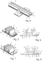
- a first embodiment of a holder 4 which consists of a base support 5, the z. B. made of plastic, stainless steel or aluminum and has a defined profile exists.
- This base support 5 has upstanding, forming a U-shaped receptacle, bearing legs 6a, 6b.
- bearing legs 6a, 6b which consist of a first portion respectively, which is formed on the side edge of the base support 5 beginning and ends at the inner edge 11, has grooves 7, and four superimposed grooves 7.
- the opposite the bearing leg 6b arranged bearing leg 6a is provided in the longitudinal direction of the insertable support rail 1 offset on the other side of the base support 5 and also has inwardly open grooves.
- Fig. 3 It can be seen that the holder 4 can be placed from below in the oblique position on the mounting rail 1. In the attached state then the holder 4 can be rotated until it pivots in the vertical position to the longitudinal axis of the support rail 1, which is made Fig. 4 is apparent. In this position, the lateral attachment webs 2, 3 engage in the grooves 7 of the two bearing legs 6a, 6b and are held therein by clamping or by sliding fit. In this preassembled state, the profiled support rail 1 can now be fastened to a surface via the two holes 8 provided in the lateral lugs of the base support 5, for example, on the bearing surface of a trapezoidal sheet of a roof construction.
- the holder 4 can also be mounted offset in height on the respectively provided on both sides mounting webs 2, 3. This is desirable if, for example, the heights of the trapezoidal sheet deviate from the rest of the trapeze by overlapping two trapezoidal sheets or unevenness of the roof truss.
- the height compensation is easy to prepare by, for example, the holder 4 is moved by a grid down or the support rail 1 is adjusted by one or two grid of the grooves up.
- a C-profile 15 is also shown in the base support 5, in which a form of spring 16 is inserted, which engages under the bottom of the support rail 1 and thus counteracts an unwanted longitudinal displacement of the support rail 1.
- the holder 4 also consists of a base support 5, the side tabs 22 and the left side has an upwardly projecting bearing leg 6a, which is firmly connected to the base support 5. These elements can be produced in one piece as a molded part, for example made of aluminum or plastic.
- the holder 4 has a defined width, for example 2 cm, and has in the bearing leg receiving grooves 7, which engage in longitudinally provided laterally on the insertable or inserted support rail fastening webs.
- the receiving grooves 7 are arranged parallel to one another at the same distance one above the other and correspond to the receiving grooves 7 in a removable and attachable bearing leg 6b.
- the grooves 7 are each arranged at the same height with the grooves in the stationary bearing leg 6a.
- the bearing leg 6b has a holding leg 18 which rests on the tab 22 of the base support 5 and is mounted thereto by means of a bow spring 19 slidably.
- This bow spring 19 engages over the movable bearing leg 6b completely and is, as can be seen from the figures, with the bridge part on the surface of the retaining leg 18.
- the holder of the free ends of the bow spring 19 in the side holes in the tabs 22 of the base support 5 are formed so that the bow spring 19 engages under bias on the surface, so that in the preassembled state, the parts of the holder 4 form a unit.
- Fügerasten 20 in the form of bead-shaped projections on the underside of the retaining leg 18 which engage in recesses on the upper side of the tab 22, define the clear opening width of the holder 4 so that he, as from FIGS. 7 and 8 can be seen from below on the support rail 1 can be placed.
- the movable bearing leg 6b is pressed after inserting the fastening webs 2, 3 in the receiving grooves 7 in the desired altitude by lateral pressure with the grooves 7 on the mounting webs 2, 3, while the Fügeraste 20 is spent in the detent position in the how out FIGS. 5 and 6 it can be seen, the support rail 1 is completely held with the mounting webs 2, 3 in the receiving grooves 7.
- a joint 21 of a spring and a groove secures the composite without the introduction of a fastening screw or a rivet in the bore 17 in the retaining leg 18, which in the closed position of the holder 4 in accordance FIGS. 5 and 6 congruent to a hole in the tab 22 of the base support 5 passes, so that both parts z. B. by means of blind rivets on a trapezoidal roof can be fastened.
Landscapes
- Engineering & Computer Science (AREA)
- Physics & Mathematics (AREA)
- Life Sciences & Earth Sciences (AREA)
- Sustainable Development (AREA)
- Sustainable Energy (AREA)
- Thermal Sciences (AREA)
- Chemical & Material Sciences (AREA)
- Combustion & Propulsion (AREA)
- Mechanical Engineering (AREA)
- General Engineering & Computer Science (AREA)
- Roof Covering Using Slabs Or Stiff Sheets (AREA)
- Bearings For Parts Moving Linearly (AREA)
Claims (14)
- Dispositif de fixation, comprenant un rail porteur (1) et des appuis (4) en forme de U, le rail porteur (1) présentant des entretoises de fixation (2, 3) faisant bilatéralement saillie vers l'extérieur au moins partiellement, pour la fixation du rail porteur (1) sur les appuis (4) en forme de U, les appuis (4) en forme de U présentant chacun un support de base (5) comprenant deux branches de support (6a, 6b) latérales qui font saillie du plan du support de base (5) et qui étant pourvues de bords intérieurs (10, 11), les branches de support (6a, 6b) comprenant des rainures de réception (7) dans lesquelles s'insèrent les entretoises de fixation (2, 3), ledit support de base (5) présentant des trous (8) pour la fixation par vissage et/ou rivetage de l'appui (4) en forme de U sur des surfaces de fixation et/ou d'autres moyens de fixation appropriés, caractérisé en ce que plusieurs rainures de réception (7) sont superposées dans les deux branches de support (6a, 6b) de manière à s'étendre parallèlement et en ce que l'écart relatif entre les rainures de réception (7) dans les deux branches de support (6a, 6b) est identique et la hauteur des rainures de réception (7) correspond à l'épaisseur des entretoises de fixation (2, 3), en ce que les branches de support (6a, 6b) sont situées en rangée les unes derrière les autres dans la direction longitudinale du rail porteur insérable, de façon décalée, sur le support de base (5) de l'appui (4) en forme de U, en ce que l'écart entre les deux bords intérieurs (10, 11) voisins des branches de support (6a, 6b) est assez grand ou en ce que les branches de support (6a, 6b) présentent des dégagements (12, 13) s'étendant de manière inclinée et parallèle les uns aux autres pour que, lorsque l'appui (4) est en position inclinée par rapport à l'axe longitudinal du rail porteur autour d'un axe vertical, le rail porteur (1) puisse être introduit dans l'espace intermédiaire entre les deux branches de support (6a, 6b) et que les entretoises de fixation (2, 3) latérales puissent pivoter à l'intérieur des rainures de réception (7) à la suite d'une rotation opposée.
- Dispositif de fixation, comprenant un rail porteur (1) et des appuis (4) en forme de U, le rail porteur (1) présentant des entretoises de fixation (2, 3) faisant bilatéralement saillie vers l'extérieur au moins partiellement, pour la fixation du rail porteur (1) sur les appuis (4) en forme de U, les appuis (4) en forme de U présentant chacun un support de base (5) comprenant deux branches de support (6a, 6b) latérales faisant saillie du plan du support de base (5), les branches de support (6a, 6b) comprenant des rainures de réception (7) dans lesquelles s'insérant les entretoises de fixation (2, 3), lequel support de base (5) présentant des trous (8) pour la fixation par vissage et/ou rivetage de l'appui (4) en forme de U sur des surfaces de fixation et/ou d'autres moyens de fixation appropriés, caractérisé en ce que plusieurs rainures de réception (7) sont superposées dans les deux branches de support (6a, 6b) de manière à s'étendre parallèlement et en ce que l'écart relatif entre les rainures de réception (7) dans les deux branches de support (6a, 6b) est identique et la hauteur des rainures de réception (7) correspond à l'épaisseur des entretoises de fixation (2, 3), en ce qu'une branche de support (6a, 6b) est agencée sur le support de base (5) de manière à pouvoir être relativement déplacée, retirée ou décalée par rapport à l'autre branche de support (6a, 6b), et en ce que, une fois les entretoises de fixation latérales (2, 3) insérées sur l'une des faces du rail porteur (1) dans les rainures de réception (7), dans la branche de support (6a) fixée sans pouvoir bouger sur le support de base (5), dans une position en hauteur définie, la branche de support (6b) agencée de manière à pouvoir être relativement déplacée, retirée ou décalée peut être posée avec ses rainures de réception (7) dans la même position en hauteur sur les entretoises de fixation (2, 3) latérales présentes sur l'autre face du rail porteur (1), et peut être fixée sur le support de base (5).
- Dispositif selon la revendication 1 ou 2, caractérisé en ce qu'au moins respectivement deux entretoises de fixation (2, 3) sont superposées dans la dimension modulaire des rainures de réception (7) correspondantes sur le rail porteur (1).
- Dispositif selon l'une quelconque des revendications précédentes, caractérisé en ce que des évidements d'encliquetage ou des parties saillantes d'encliquetage sont situé(e)s sur au moins une nervure intermédiaire des rainures de réception (7) au moins unilatéralement, et coopèrent avec des parties saillantes d'encliquetage correspondantes ou des évidements d'encliquetage correspondants sur au moins une entretoise de fixation (2, 3), une fois les entretoises de fixation (2, 3) entrées par pivotement.
- Dispositif selon la revendication 1 ou 2, caractérisé en ce que les trous (8) ou des moyens de fixation sont situés sur le support de base (5) sur des languettes qui font saillie latéralement des branches de support (6a, 6b).
- Dispositif selon les revendications 2 et 5, caractérisé en ce que, de manière identique au ou aux trous (8) dans une languette du support de base (5), qui reçoit la branche de support (6b) agencée de manière à pouvoir être relativement déplacée, retirée ou décalée, un trou (17) ou un trou oblong est ménagé transversalement à la direction longitudinale du rail porteur (1) dans une branche de retenue (18) de la branche de support (6b).
- Dispositif selon la revendication 2, caractérisé en ce que des guidages s'insérant dans des guidages correspondants sur le support de base (1) sont situés sur la branche de support (6b) agencée de manière à pouvoir être relativement déplacée, retirée ou décalée.
- Dispositif selon la revendication 2 ou 7, caractérisé en ce que sur le support de base (1) est monté un ressort en étrier (19) qui vient au moins partiellement se plaquer au-dessus au moins de parties de la branche de support (6b) agencée de manière à pouvoir être relativement déplacée, retirée ou décalée, en retenant celle-ci sur le support de base (1) de manière ajustable.
- Dispositif selon la revendication 1 ou 2, caractérisé en ce qu'un trou fileté ou un trou dans lequel une vis de blocage ou une vis de blocage autotaraudeuse peut être vissée, laquelle exerce une pression sur le support de base (5) en vue de la fixation ou s'enfonce par sa pointe dans la surface, est ménagé au moins en un point de fixation d'un appui (4) sur le rail porteur (1) dans la paroi de fond (14).
- Dispositif selon la revendication 1, caractérisé en ce que des éléments d'arrêt faisant saillie en forme de coin, qui pénètrent dans les surfaces avant des entretoises de fixation (2, 3) lorsque l'appui (4) est amené en rotation, sont situés dans le fond des rainures de réception (7).
- Dispositif selon la revendication 1 ou 2, caractérisé en ce que l'ajustement entre les rainures de réception (7) et les entretoises de fixation (2, 3) est un ajustement glissant et/ou un ajustement de serrage.
- Dispositif selon la revendication 1 ou 2, caractérisé en ce que le rail porteur (1) est conçu pour la fixation d'un module solaire ou photovoltaïque et présente un profilé en C.
- Dispositif selon la revendication 1 ou 2, caractérisé en ce qu'un logement pour un ressort de retenu (16), qui vient se plaquer sous la face inférieure du rail porteur (1) dans l'état inséré ou s'insère dans une rainure ménagée dans celui-ci, est situé côté supérieur dans le support de base (5).
- Dispositif selon la revendication 1 ou 2, caractérisé en ce que l'appui (4) et/ou le rail porteur (1) sont constitués de matière plastique, d'aluminium ou d'acier inoxydable.
Applications Claiming Priority (2)
| Application Number | Priority Date | Filing Date | Title |
|---|---|---|---|
| DE202010008389U DE202010008389U1 (de) | 2010-08-27 | 2010-08-27 | Vorrichtung zum Befestigen einer Tragschiene |
| DE202011000172U DE202011000172U1 (de) | 2010-08-27 | 2011-01-25 | Vorrichtung zum Befestigen einer Tragschiene |
Publications (3)
| Publication Number | Publication Date |
|---|---|
| EP2423622A2 EP2423622A2 (fr) | 2012-02-29 |
| EP2423622A3 EP2423622A3 (fr) | 2014-10-01 |
| EP2423622B1 true EP2423622B1 (fr) | 2017-08-23 |
Family
ID=43070178
Family Applications (1)
| Application Number | Title | Priority Date | Filing Date |
|---|---|---|---|
| EP11177666.2A Active EP2423622B1 (fr) | 2010-08-27 | 2011-08-16 | Dispositif de fixation avec éléments de montage et rail de support |
Country Status (2)
| Country | Link |
|---|---|
| EP (1) | EP2423622B1 (fr) |
| DE (2) | DE202010008389U1 (fr) |
Cited By (3)
| Publication number | Priority date | Publication date | Assignee | Title |
|---|---|---|---|---|
| WO2023248254A1 (fr) * | 2022-06-25 | 2023-12-28 | Sunrack Technologies Llp | Structure de rail long à base de cale en u pour montage de système de module solaire |
| US12003206B2 (en) | 2021-08-24 | 2024-06-04 | Ironridge, Inc. | Rail-based solar panel mounting system |
| EP4075077B1 (fr) * | 2021-04-15 | 2024-12-18 | Renusol Europe GmbH | Système de fixation de panneaux solaires |
Families Citing this family (3)
| Publication number | Priority date | Publication date | Assignee | Title |
|---|---|---|---|---|
| DE102011101186A1 (de) * | 2011-05-09 | 2012-11-15 | Creotecc Gmbh | Klemmhalter und Klemmhaltersystem zur Montage eines Tragprofils für Photovoltaikmodule auf einem Dach |
| US20130048816A1 (en) * | 2011-08-31 | 2013-02-28 | Stuart H. Wentworth | Rackless Height Adjustable Mount For Attaching An Article To A Roof |
| NL2030923B1 (nl) * | 2022-02-14 | 2023-08-18 | Van Der Valk Systemen B V | Bevestigingsinrichting, dakhaak, montagerail en werkwijze voor de bevestiging van objecten op een dak |
Family Cites Families (13)
| Publication number | Priority date | Publication date | Assignee | Title |
|---|---|---|---|---|
| DE19502225C2 (de) | 1995-01-25 | 1997-07-10 | Maier G Paschal Werk | Anhängevorrichtung zum Anhängen wenigstens einer Schaltafel an ein Hebezeug |
| DE19802997A1 (de) | 1998-01-27 | 1999-08-05 | Dlw Ag | Dach- und/oder Wandaufbau sowie Verwendung hiervon |
| EP1147270B1 (fr) * | 1999-01-08 | 2006-09-20 | Corus Bausysteme GmbH | Elements de retenue pour toles de constructions metalliques |
| DE10106309C2 (de) | 2001-02-12 | 2003-03-27 | Ibc Solartechnik Ag | Photovoltaikmodule und Photovoltaikanlage |
| NL1020620C2 (nl) | 2002-05-17 | 2003-11-21 | Alcoa Nederland Bv | Draagsysteem voor zonnepanelen. |
| DE10336019A1 (de) * | 2003-08-01 | 2005-03-10 | Moeding Keramikfassaden Gmbh | Vorgehängte Fassadenkonstruktion |
| DE202005003717U1 (de) | 2005-03-04 | 2005-06-23 | Ibc Solar Ag | Befestigungsvorrichtung zur Befestigung eines Montageprofils für Solarmodule oder Solarkollektoren an ein Trägerprofil, insbesondere ein Trapez- oder Sandwichprofil |
| DE102006000089A1 (de) | 2006-02-23 | 2007-08-30 | Hilti Ag | Befestigungsvorrichtung für die Befestigung von Solarpaneelen an einer Montageschiene |
| DE202007016011U1 (de) * | 2007-11-15 | 2008-04-17 | Meier, Christian | Haltevorrichtung für Solarmodule eines Solarfeldes |
| NL2001200C2 (nl) | 2008-01-18 | 2009-07-21 | Walraven Holding Bv J Van | Bevestiging voor zonnepanelen. |
| DE202009001810U1 (de) | 2009-02-06 | 2009-04-16 | K2 Systems Gmbh | Solarmodulbefestigung |
| DE202009004746U1 (de) | 2009-04-28 | 2009-07-23 | Kumatec Sondermaschinenbau & Kunststoffverarbeitung Gmbh | Befestigungseinrichtung zum Fixieren eines Holmes oder einer Leiste an einem C-Profil |
| FR2962797B1 (fr) * | 2010-07-19 | 2014-02-14 | Tenesol | Structure de montage d'un panneau de recuperation d'energie solaire sur un support, systeme comprenant une telle structure, installation comprenant un tel systeme, procede de montage d'un systeme de recuperation d'energie solaire sur un support |
-
2010
- 2010-08-27 DE DE202010008389U patent/DE202010008389U1/de not_active Expired - Lifetime
-
2011
- 2011-01-25 DE DE202011000172U patent/DE202011000172U1/de not_active Expired - Lifetime
- 2011-08-16 EP EP11177666.2A patent/EP2423622B1/fr active Active
Non-Patent Citations (1)
| Title |
|---|
| None * |
Cited By (4)
| Publication number | Priority date | Publication date | Assignee | Title |
|---|---|---|---|---|
| EP4075077B1 (fr) * | 2021-04-15 | 2024-12-18 | Renusol Europe GmbH | Système de fixation de panneaux solaires |
| US12003206B2 (en) | 2021-08-24 | 2024-06-04 | Ironridge, Inc. | Rail-based solar panel mounting system |
| US12506436B2 (en) | 2021-08-24 | 2025-12-23 | Ironridge, Inc. | Rail-based solar panel mounting system |
| WO2023248254A1 (fr) * | 2022-06-25 | 2023-12-28 | Sunrack Technologies Llp | Structure de rail long à base de cale en u pour montage de système de module solaire |
Also Published As
| Publication number | Publication date |
|---|---|
| DE202011000172U1 (de) | 2011-04-21 |
| DE202010008389U1 (de) | 2010-11-11 |
| EP2423622A3 (fr) | 2014-10-01 |
| EP2423622A2 (fr) | 2012-02-29 |
Similar Documents
| Publication | Publication Date | Title |
|---|---|---|
| EP2003405B1 (fr) | Dispositif de fixation pour des composants plats installés sur un bâti, en particulier pour des modules solaires | |
| EP2315982B1 (fr) | Structure de fixation destinée à un module solaire de grande surface et module solaire | |
| EP2691704B1 (fr) | Agencement avec modules de fixation destinés à fixer des modules solaires | |
| EP2270403B1 (fr) | Collecteur solaire avec rail de support | |
| DE102012011969A1 (de) | Solarmodulhalter | |
| EP2390513A1 (fr) | Dispositif destiné à lier un rail de profilé avec un autre composant | |
| EP2224185A1 (fr) | Carcan (liaison mécanique) | |
| EP2333452A2 (fr) | Dispositif de fixation | |
| DE102007033323B4 (de) | Befestigungseinrichtung für an einem Gestellaufbau anzuordnende flächige Bauteile, insbesondere Solarmodule | |
| DE202009004746U1 (de) | Befestigungseinrichtung zum Fixieren eines Holmes oder einer Leiste an einem C-Profil | |
| EP2423622A2 (fr) | Dispositif de fixation d'un rail de support | |
| DE102010022845B4 (de) | Kantenschutzelement für die Anordnung ungerahmter PV-Module | |
| EP2221557A1 (fr) | Liaison crantée | |
| EP2194341A2 (fr) | Verrouillage de module | |
| DE102009055948A1 (de) | Profilelement eines Daches und Anordnung von Profilelementen | |
| DE202010012937U1 (de) | Befestigungssystem | |
| DE202009005090U1 (de) | Anordnung zur Befestigung von Modulen einer Photovoltaik-Einrichtung oder von Solarpaneelen | |
| EP2554925B1 (fr) | Élément d'appui pour un module solaire | |
| DE202021104820U1 (de) | Befestigungsvorrichtung zur Befestigung eines einen Teil eines Daches eines Gebäudes bildenden Photovoltaikmoduls am Gebäude und Verbindungsvorrichtungen zur Verbindung solcher Photovoltaikmodule miteinander | |
| EP1647649A2 (fr) | Système de fixation de façades | |
| DE202010008417U1 (de) | Montageanordnung für mindestens ein PV-Modul, insbesondere Solarzellenmodul oder/und Solarthermiemodul | |
| EP2423620A2 (fr) | Vis autoperceuses pour la fixation de panneaux solaires | |
| DE202011052032U1 (de) | Stützelement für ein Solarmodul | |
| DE102010028566A1 (de) | Solarmodultragvorrichtung | |
| WO2012104423A1 (fr) | Élément de maintien réglable pour toits à profil trapézoïdal |
Legal Events
| Date | Code | Title | Description |
|---|---|---|---|
| AK | Designated contracting states |
Kind code of ref document: A2 Designated state(s): AL AT BE BG CH CY CZ DE DK EE ES FI FR GB GR HR HU IE IS IT LI LT LU LV MC MK MT NL NO PL PT RO RS SE SI SK SM TR |
|
| AX | Request for extension of the european patent |
Extension state: BA ME |
|
| PUAI | Public reference made under article 153(3) epc to a published international application that has entered the european phase |
Free format text: ORIGINAL CODE: 0009012 |
|
| PUAL | Search report despatched |
Free format text: ORIGINAL CODE: 0009013 |
|
| AK | Designated contracting states |
Kind code of ref document: A3 Designated state(s): AL AT BE BG CH CY CZ DE DK EE ES FI FR GB GR HR HU IE IS IT LI LT LU LV MC MK MT NL NO PL PT RO RS SE SI SK SM TR |
|
| AX | Request for extension of the european patent |
Extension state: BA ME |
|
| RIC1 | Information provided on ipc code assigned before grant |
Ipc: F24J 2/52 20060101AFI20140826BHEP |
|
| 17P | Request for examination filed |
Effective date: 20150311 |
|
| RBV | Designated contracting states (corrected) |
Designated state(s): AL AT BE BG CH CY CZ DE DK EE ES FI FR GB GR HR HU IE IS IT LI LT LU LV MC MK MT NL NO PL PT RO RS SE SI SK SM TR |
|
| GRAP | Despatch of communication of intention to grant a patent |
Free format text: ORIGINAL CODE: EPIDOSNIGR1 |
|
| INTG | Intention to grant announced |
Effective date: 20170531 |
|
| GRAS | Grant fee paid |
Free format text: ORIGINAL CODE: EPIDOSNIGR3 |
|
| GRAA | (expected) grant |
Free format text: ORIGINAL CODE: 0009210 |
|
| AK | Designated contracting states |
Kind code of ref document: B1 Designated state(s): AL AT BE BG CH CY CZ DE DK EE ES FI FR GB GR HR HU IE IS IT LI LT LU LV MC MK MT NL NO PL PT RO RS SE SI SK SM TR |
|
| REG | Reference to a national code |
Ref country code: GB Ref legal event code: FG4D Free format text: NOT ENGLISH |
|
| REG | Reference to a national code |
Ref country code: CH Ref legal event code: EP |
|
| REG | Reference to a national code |
Ref country code: AT Ref legal event code: REF Ref document number: 921781 Country of ref document: AT Kind code of ref document: T Effective date: 20170915 |
|
| REG | Reference to a national code |
Ref country code: IE Ref legal event code: FG4D Free format text: LANGUAGE OF EP DOCUMENT: GERMAN |
|
| REG | Reference to a national code |
Ref country code: DE Ref legal event code: R096 Ref document number: 502011012840 Country of ref document: DE |
|
| REG | Reference to a national code |
Ref country code: DE Ref legal event code: R079 Ref document number: 502011012840 Country of ref document: DE Free format text: PREVIOUS MAIN CLASS: F24J0002520000 Ipc: F24S0025000000 |
|
| REG | Reference to a national code |
Ref country code: NL Ref legal event code: MP Effective date: 20170823 |
|
| REG | Reference to a national code |
Ref country code: LT Ref legal event code: MG4D |
|
| PG25 | Lapsed in a contracting state [announced via postgrant information from national office to epo] |
Ref country code: NO Free format text: LAPSE BECAUSE OF FAILURE TO SUBMIT A TRANSLATION OF THE DESCRIPTION OR TO PAY THE FEE WITHIN THE PRESCRIBED TIME-LIMIT Effective date: 20171123 Ref country code: FI Free format text: LAPSE BECAUSE OF FAILURE TO SUBMIT A TRANSLATION OF THE DESCRIPTION OR TO PAY THE FEE WITHIN THE PRESCRIBED TIME-LIMIT Effective date: 20170823 Ref country code: NL Free format text: LAPSE BECAUSE OF FAILURE TO SUBMIT A TRANSLATION OF THE DESCRIPTION OR TO PAY THE FEE WITHIN THE PRESCRIBED TIME-LIMIT Effective date: 20170823 Ref country code: LT Free format text: LAPSE BECAUSE OF FAILURE TO SUBMIT A TRANSLATION OF THE DESCRIPTION OR TO PAY THE FEE WITHIN THE PRESCRIBED TIME-LIMIT Effective date: 20170823 Ref country code: SE Free format text: LAPSE BECAUSE OF FAILURE TO SUBMIT A TRANSLATION OF THE DESCRIPTION OR TO PAY THE FEE WITHIN THE PRESCRIBED TIME-LIMIT Effective date: 20170823 Ref country code: HR Free format text: LAPSE BECAUSE OF FAILURE TO SUBMIT A TRANSLATION OF THE DESCRIPTION OR TO PAY THE FEE WITHIN THE PRESCRIBED TIME-LIMIT Effective date: 20170823 |
|
| PG25 | Lapsed in a contracting state [announced via postgrant information from national office to epo] |
Ref country code: RS Free format text: LAPSE BECAUSE OF FAILURE TO SUBMIT A TRANSLATION OF THE DESCRIPTION OR TO PAY THE FEE WITHIN THE PRESCRIBED TIME-LIMIT Effective date: 20170823 Ref country code: IS Free format text: LAPSE BECAUSE OF FAILURE TO SUBMIT A TRANSLATION OF THE DESCRIPTION OR TO PAY THE FEE WITHIN THE PRESCRIBED TIME-LIMIT Effective date: 20171223 Ref country code: GR Free format text: LAPSE BECAUSE OF FAILURE TO SUBMIT A TRANSLATION OF THE DESCRIPTION OR TO PAY THE FEE WITHIN THE PRESCRIBED TIME-LIMIT Effective date: 20171124 Ref country code: ES Free format text: LAPSE BECAUSE OF FAILURE TO SUBMIT A TRANSLATION OF THE DESCRIPTION OR TO PAY THE FEE WITHIN THE PRESCRIBED TIME-LIMIT Effective date: 20170823 Ref country code: LV Free format text: LAPSE BECAUSE OF FAILURE TO SUBMIT A TRANSLATION OF THE DESCRIPTION OR TO PAY THE FEE WITHIN THE PRESCRIBED TIME-LIMIT Effective date: 20170823 Ref country code: PL Free format text: LAPSE BECAUSE OF FAILURE TO SUBMIT A TRANSLATION OF THE DESCRIPTION OR TO PAY THE FEE WITHIN THE PRESCRIBED TIME-LIMIT Effective date: 20170823 Ref country code: BG Free format text: LAPSE BECAUSE OF FAILURE TO SUBMIT A TRANSLATION OF THE DESCRIPTION OR TO PAY THE FEE WITHIN THE PRESCRIBED TIME-LIMIT Effective date: 20171123 |
|
| PG25 | Lapsed in a contracting state [announced via postgrant information from national office to epo] |
Ref country code: RO Free format text: LAPSE BECAUSE OF FAILURE TO SUBMIT A TRANSLATION OF THE DESCRIPTION OR TO PAY THE FEE WITHIN THE PRESCRIBED TIME-LIMIT Effective date: 20170823 Ref country code: DK Free format text: LAPSE BECAUSE OF FAILURE TO SUBMIT A TRANSLATION OF THE DESCRIPTION OR TO PAY THE FEE WITHIN THE PRESCRIBED TIME-LIMIT Effective date: 20170823 Ref country code: CZ Free format text: LAPSE BECAUSE OF FAILURE TO SUBMIT A TRANSLATION OF THE DESCRIPTION OR TO PAY THE FEE WITHIN THE PRESCRIBED TIME-LIMIT Effective date: 20170823 |
|
| REG | Reference to a national code |
Ref country code: DE Ref legal event code: R097 Ref document number: 502011012840 Country of ref document: DE |
|
| PG25 | Lapsed in a contracting state [announced via postgrant information from national office to epo] |
Ref country code: SM Free format text: LAPSE BECAUSE OF FAILURE TO SUBMIT A TRANSLATION OF THE DESCRIPTION OR TO PAY THE FEE WITHIN THE PRESCRIBED TIME-LIMIT Effective date: 20170823 Ref country code: EE Free format text: LAPSE BECAUSE OF FAILURE TO SUBMIT A TRANSLATION OF THE DESCRIPTION OR TO PAY THE FEE WITHIN THE PRESCRIBED TIME-LIMIT Effective date: 20170823 Ref country code: SK Free format text: LAPSE BECAUSE OF FAILURE TO SUBMIT A TRANSLATION OF THE DESCRIPTION OR TO PAY THE FEE WITHIN THE PRESCRIBED TIME-LIMIT Effective date: 20170823 Ref country code: IT Free format text: LAPSE BECAUSE OF FAILURE TO SUBMIT A TRANSLATION OF THE DESCRIPTION OR TO PAY THE FEE WITHIN THE PRESCRIBED TIME-LIMIT Effective date: 20170823 |
|
| PLBE | No opposition filed within time limit |
Free format text: ORIGINAL CODE: 0009261 |
|
| STAA | Information on the status of an ep patent application or granted ep patent |
Free format text: STATUS: NO OPPOSITION FILED WITHIN TIME LIMIT |
|
| 26N | No opposition filed |
Effective date: 20180524 |
|
| PG25 | Lapsed in a contracting state [announced via postgrant information from national office to epo] |
Ref country code: SI Free format text: LAPSE BECAUSE OF FAILURE TO SUBMIT A TRANSLATION OF THE DESCRIPTION OR TO PAY THE FEE WITHIN THE PRESCRIBED TIME-LIMIT Effective date: 20170823 |
|
| PG25 | Lapsed in a contracting state [announced via postgrant information from national office to epo] |
Ref country code: MT Free format text: LAPSE BECAUSE OF FAILURE TO SUBMIT A TRANSLATION OF THE DESCRIPTION OR TO PAY THE FEE WITHIN THE PRESCRIBED TIME-LIMIT Effective date: 20170823 |
|
| PG25 | Lapsed in a contracting state [announced via postgrant information from national office to epo] |
Ref country code: MC Free format text: LAPSE BECAUSE OF FAILURE TO SUBMIT A TRANSLATION OF THE DESCRIPTION OR TO PAY THE FEE WITHIN THE PRESCRIBED TIME-LIMIT Effective date: 20170823 |
|
| REG | Reference to a national code |
Ref country code: CH Ref legal event code: PL |
|
| GBPC | Gb: european patent ceased through non-payment of renewal fee |
Effective date: 20180816 |
|
| PG25 | Lapsed in a contracting state [announced via postgrant information from national office to epo] |
Ref country code: LI Free format text: LAPSE BECAUSE OF NON-PAYMENT OF DUE FEES Effective date: 20180831 Ref country code: CH Free format text: LAPSE BECAUSE OF NON-PAYMENT OF DUE FEES Effective date: 20180831 Ref country code: LU Free format text: LAPSE BECAUSE OF NON-PAYMENT OF DUE FEES Effective date: 20180816 |
|
| REG | Reference to a national code |
Ref country code: BE Ref legal event code: MM Effective date: 20180831 |
|
| REG | Reference to a national code |
Ref country code: IE Ref legal event code: MM4A |
|
| PG25 | Lapsed in a contracting state [announced via postgrant information from national office to epo] |
Ref country code: IE Free format text: LAPSE BECAUSE OF NON-PAYMENT OF DUE FEES Effective date: 20180816 |
|
| PG25 | Lapsed in a contracting state [announced via postgrant information from national office to epo] |
Ref country code: BE Free format text: LAPSE BECAUSE OF NON-PAYMENT OF DUE FEES Effective date: 20180831 Ref country code: FR Free format text: LAPSE BECAUSE OF NON-PAYMENT OF DUE FEES Effective date: 20180831 |
|
| REG | Reference to a national code |
Ref country code: AT Ref legal event code: MM01 Ref document number: 921781 Country of ref document: AT Kind code of ref document: T Effective date: 20180816 |
|
| PG25 | Lapsed in a contracting state [announced via postgrant information from national office to epo] |
Ref country code: GB Free format text: LAPSE BECAUSE OF NON-PAYMENT OF DUE FEES Effective date: 20180816 |
|
| PG25 | Lapsed in a contracting state [announced via postgrant information from national office to epo] |
Ref country code: AT Free format text: LAPSE BECAUSE OF NON-PAYMENT OF DUE FEES Effective date: 20180816 |
|
| PG25 | Lapsed in a contracting state [announced via postgrant information from national office to epo] |
Ref country code: TR Free format text: LAPSE BECAUSE OF FAILURE TO SUBMIT A TRANSLATION OF THE DESCRIPTION OR TO PAY THE FEE WITHIN THE PRESCRIBED TIME-LIMIT Effective date: 20170823 |
|
| PG25 | Lapsed in a contracting state [announced via postgrant information from national office to epo] |
Ref country code: HU Free format text: LAPSE BECAUSE OF FAILURE TO SUBMIT A TRANSLATION OF THE DESCRIPTION OR TO PAY THE FEE WITHIN THE PRESCRIBED TIME-LIMIT; INVALID AB INITIO Effective date: 20110816 Ref country code: PT Free format text: LAPSE BECAUSE OF FAILURE TO SUBMIT A TRANSLATION OF THE DESCRIPTION OR TO PAY THE FEE WITHIN THE PRESCRIBED TIME-LIMIT Effective date: 20170823 |
|
| PG25 | Lapsed in a contracting state [announced via postgrant information from national office to epo] |
Ref country code: CY Free format text: LAPSE BECAUSE OF FAILURE TO SUBMIT A TRANSLATION OF THE DESCRIPTION OR TO PAY THE FEE WITHIN THE PRESCRIBED TIME-LIMIT Effective date: 20170823 Ref country code: MK Free format text: LAPSE BECAUSE OF NON-PAYMENT OF DUE FEES Effective date: 20170823 |
|
| PG25 | Lapsed in a contracting state [announced via postgrant information from national office to epo] |
Ref country code: AL Free format text: LAPSE BECAUSE OF FAILURE TO SUBMIT A TRANSLATION OF THE DESCRIPTION OR TO PAY THE FEE WITHIN THE PRESCRIBED TIME-LIMIT Effective date: 20170823 |
|
| P01 | Opt-out of the competence of the unified patent court (upc) registered |
Effective date: 20230501 |
|
| P02 | Opt-out of the competence of the unified patent court (upc) changed |
Effective date: 20230515 |
|
| PGFP | Annual fee paid to national office [announced via postgrant information from national office to epo] |
Ref country code: DE Payment date: 20250815 Year of fee payment: 15 |