EP2003479B1 - Telezoomobjektiv mit hohem Vergrösserungsverhältnis - Google Patents
Telezoomobjektiv mit hohem Vergrösserungsverhältnis Download PDFInfo
- Publication number
- EP2003479B1 EP2003479B1 EP07715031A EP07715031A EP2003479B1 EP 2003479 B1 EP2003479 B1 EP 2003479B1 EP 07715031 A EP07715031 A EP 07715031A EP 07715031 A EP07715031 A EP 07715031A EP 2003479 B1 EP2003479 B1 EP 2003479B1
- Authority
- EP
- European Patent Office
- Prior art keywords
- lens group
- lens
- denotes
- zoom ratio
- lens system
- Prior art date
- Legal status (The legal status is an assumption and is not a legal conclusion. Google has not performed a legal analysis and makes no representation as to the accuracy of the status listed.)
- Not-in-force
Links
- 238000003384 imaging method Methods 0.000 claims abstract description 133
- 230000003287 optical effect Effects 0.000 claims abstract description 42
- 230000014509 gene expression Effects 0.000 claims description 35
- 239000003973 paint Substances 0.000 claims description 4
- 230000009467 reduction Effects 0.000 abstract description 28
- 230000002093 peripheral effect Effects 0.000 abstract description 7
- 230000005499 meniscus Effects 0.000 description 21
- 230000004075 alteration Effects 0.000 description 17
- 238000010586 diagram Methods 0.000 description 10
- 230000000694 effects Effects 0.000 description 8
- 238000010276 construction Methods 0.000 description 7
- 206010010071 Coma Diseases 0.000 description 6
- 238000012937 correction Methods 0.000 description 4
- 239000011521 glass Substances 0.000 description 3
- 238000000034 method Methods 0.000 description 3
- 230000008569 process Effects 0.000 description 3
- 239000006059 cover glass Substances 0.000 description 2
- 239000000463 material Substances 0.000 description 2
- 201000009310 astigmatism Diseases 0.000 description 1
- 239000011248 coating agent Substances 0.000 description 1
- 238000000576 coating method Methods 0.000 description 1
- 150000001875 compounds Chemical class 0.000 description 1
- 230000006870 function Effects 0.000 description 1
- 230000007246 mechanism Effects 0.000 description 1
- 238000000465 moulding Methods 0.000 description 1
- 230000011514 reflex Effects 0.000 description 1
- 239000011347 resin Substances 0.000 description 1
- 229920005989 resin Polymers 0.000 description 1
- 238000002834 transmittance Methods 0.000 description 1
Images


Classifications
-
- G—PHYSICS
- G02—OPTICS
- G02B—OPTICAL ELEMENTS, SYSTEMS OR APPARATUS
- G02B27/00—Optical systems or apparatus not provided for by any of the groups G02B1/00 - G02B26/00, G02B30/00
- G02B27/64—Imaging systems using optical elements for stabilisation of the lateral and angular position of the image
- G02B27/646—Imaging systems using optical elements for stabilisation of the lateral and angular position of the image compensating for small deviations, e.g. due to vibration or shake
-
- G—PHYSICS
- G02—OPTICS
- G02B—OPTICAL ELEMENTS, SYSTEMS OR APPARATUS
- G02B15/00—Optical objectives with means for varying the magnification
- G02B15/14—Optical objectives with means for varying the magnification by axial movement of one or more lenses or groups of lenses relative to the image plane for continuously varying the equivalent focal length of the objective
- G02B15/145—Optical objectives with means for varying the magnification by axial movement of one or more lenses or groups of lenses relative to the image plane for continuously varying the equivalent focal length of the objective having five groups only
- G02B15/1451—Optical objectives with means for varying the magnification by axial movement of one or more lenses or groups of lenses relative to the image plane for continuously varying the equivalent focal length of the objective having five groups only the first group being positive
- G02B15/145129—Optical objectives with means for varying the magnification by axial movement of one or more lenses or groups of lenses relative to the image plane for continuously varying the equivalent focal length of the objective having five groups only the first group being positive arranged +-+++
-
- G—PHYSICS
- G03—PHOTOGRAPHY; CINEMATOGRAPHY; ANALOGOUS TECHNIQUES USING WAVES OTHER THAN OPTICAL WAVES; ELECTROGRAPHY; HOLOGRAPHY
- G03B—APPARATUS OR ARRANGEMENTS FOR TAKING PHOTOGRAPHS OR FOR PROJECTING OR VIEWING THEM; APPARATUS OR ARRANGEMENTS EMPLOYING ANALOGOUS TECHNIQUES USING WAVES OTHER THAN OPTICAL WAVES; ACCESSORIES THEREFOR
- G03B5/00—Adjustment of optical system relative to image or object surface other than for focusing
-
- H—ELECTRICITY
- H04—ELECTRIC COMMUNICATION TECHNIQUE
- H04N—PICTORIAL COMMUNICATION, e.g. TELEVISION
- H04N23/00—Cameras or camera modules comprising electronic image sensors; Control thereof
- H04N23/60—Control of cameras or camera modules
- H04N23/68—Control of cameras or camera modules for stable pick-up of the scene, e.g. compensating for camera body vibrations
- H04N23/682—Vibration or motion blur correction
- H04N23/685—Vibration or motion blur correction performed by mechanical compensation
- H04N23/687—Vibration or motion blur correction performed by mechanical compensation by shifting the lens or sensor position
-
- G—PHYSICS
- G02—OPTICS
- G02B—OPTICAL ELEMENTS, SYSTEMS OR APPARATUS
- G02B27/00—Optical systems or apparatus not provided for by any of the groups G02B1/00 - G02B26/00, G02B30/00
- G02B27/0018—Optical systems or apparatus not provided for by any of the groups G02B1/00 - G02B26/00, G02B30/00 with means for preventing ghost images
-
- G—PHYSICS
- G02—OPTICS
- G02B—OPTICAL ELEMENTS, SYSTEMS OR APPARATUS
- G02B7/00—Mountings, adjusting means, or light-tight connections, for optical elements
- G02B7/02—Mountings, adjusting means, or light-tight connections, for optical elements for lenses
- G02B7/021—Mountings, adjusting means, or light-tight connections, for optical elements for lenses for more than one lens
Definitions
- the present invention relates to an imaging apparatus, an imaging method and a high zoom ratio zoom lens system.
- an imaging apparatus that reads out image information in a designated image frame as an object image from image information obtained by a solid-state imaging device, and is suitably changing the read out position of the designated image frame in accordance with variation in a position of the object image caused by a play of the lens barrel upon zooming a zoom lens system so as to correct the variation (for example, Japanese Patent Application Laid-Open No. 5-37849 ).
- an imaging apparatus capable of moving a solid-state imaging device in a direction along an optical axis in order to correct variation in an object image position along the optical axis caused upon zooming (for example, Japanese Patent Application Laid-Open No. 6-339054 ).
- the imaging apparatus disclosed in Japanese Patent Application Laid-Open No. 6-339054 can efficiently use effective pixels of the solid-state imaging device.
- variation in the object image position caused by moving the solid-state imaging device along the optical axis is be corrected, light quantity becomes uneven on the corner of the object image.
- the present invention is made in view of the aforementioned problems and has an object to provide an imaging apparatus, an imaging method, and a high zoom ratio zoom lens system carrying out vibration reduction by moving a solid-state imaging device in a direction substantially perpendicular to an optical axis, capable of efficiently using effective pixels of the solid-state imaging device, and capable of securing an excellent peripheral light quantity ratio of an object image even upon carrying out vibration reduction.
- an imaging apparatus comprising: a high zoom ratio zoom lens system comprising, in order from an object, a first lens group having positive refractive power, a second lens group having negative refractive power, a third lens group, a fourth lens group, and a fifth lens group, upon zooming from a wide-angle end state to a telephoto end state, the first lens group, the second lens group, the third lens group, and the fourth lens group being moved along an optical axis; a solid-state imaging device capturing an object image formed by the high zoom ratio zoom lens system; a detecting member that detects variation in a position of the object image; a driving member that moves the solid-state imaging device in a direction substantially perpendicular to the optical axis; a control member that controls the driving member in order to correct variation in the position of the object image; and a shield member with an aperture portion for limiting bundle of rays incident on the periphery of the most object side lens in the first lens group of
- an imaging method for capturing an object image formed by a high zoom ratio zoom lens system by means of a solid-state imaging device with detecting variation in a position of the object image, and moving the solid-state imaging device in a direction substantially perpendicular to the optical axis so as to correct variation in the position of the object image comprising steps of: providing the high zoom ratio zoom lens system comprising, in order from the object, a first lens group having positive refractive power, a second lens group having negative refractive power, a third lens group, a fourth lens group, and a fifth lens group, upon zooming from a wide-angle end state to a telephoto end state, the first lens group, the second lens group, the third lens group, and the fourth lens group being moved along the optical axis; limiting bundle of rays incident on the periphery of the most object side lens in the first lens group of the high zoom ratio zoom lens system by a shield member with an aperture portion; and satisfying the
- An imaging apparatus including: a high zoom ratio zoom lens system comprising, in order from an object, a first lens group having positive refractive power, a second lens group having negative refractive power, a third lens group having positive refractive power, a fourth lens group having positive refractive power, and a fifth lens group having positive refractive power, upon zooming from a wide-angle end state to a telephoto end state, the first lens group, the second lens group, the third lens group, and the fourth lens group being moved along an optical axis; a solid-state imaging device capturing an object image formed by the high zoom ratio zoom lens system; a detecting member that detects variation in a position of the object image; a driving member that moves the solid-state imaging device in a direction substantially perpendicular to the optical axis; a control member that controls the driving member in order to correct variation in the position of the object image; and a shield member with an aperture portion for limiting bundle of rays incident on the periphery of the most object
- Conditional expression (1) defines the diameter of the aperture portion in the shield member.
- the aperture portion of the shield member is preferably an aperture having a circular shape.
- the aperture portion has a rotational symmetry centered on the optical axis, desired shield effect can be obtained without performing rotational adjustment.
- the inner diameter of the aperture portion having a circular shape becomes ⁇ 1 in conditional expression (1).
- the aperture portion of the shield member is preferably an aperture having a rectangular shape corresponding to the solid-state imaging device.
- the shape of the aperture portion of the shield member With this construction, it becomes possible to set the shape of the aperture portion of the shield member to be an external shape of effective pixels of the solid-state imaging device projected on the most object side lens surface in the first lens group. Accordingly, it becomes possible to effectively prevent stray light from entering into the high zoom ratio zoom lens system.
- the diagonal length of the aperture portion having a rectangular shape becomes ⁇ 1 in conditional expression (1).
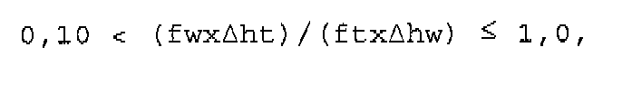
- conditional expression (2) is preferably satisfied: 0.10 ⁇ fw ⁇ ⁇ ht / ft ⁇ ⁇ hw ⁇ 1.0 where fw denotes a focal length of the high zoom ratio zoom lens system in the wide-angle end state, ft denotes a focal length of the high zoom ratio zoom lens system in the telephoto end state, and ⁇ ht denotes the maximum moving amount of the solid-state imaging device in the telephoto end state.
- Conditional expression (2) defines an appropriate range of the maximum moving amount of the solid-state imaging device and a focal length of the high zoom ratio zoom lens system.
- the shield member is made up by applying shielding paint on the most object side lens surface of the first lens group.
- the shield member is preferably a plate-like member disposed on the most object side lens surface of the first lens group of the high zoom ratio zoom lens system.
- the above-described plate-like member includes a thin sheet member.
- the shield member is preferably formed in a body with a lens-fixing member for fixing the most object side lens of the first lens group in the high zoom ratio zoom lens system.
- the high zoom ratio zoom lens system preferably carries out focusing by moving the fifth lens group along the optical axis.
- the fourth lens group of the high zoom ratio zoom lens system is preferably composed of, in order from the object, a front group having positive refractive power, and a rear group having negative refractive power, and the following conditional expression (3) is preferably satisfied: - 0.45 ⁇ f ⁇ 4 ⁇ F + f ⁇ 4 ⁇ R / f ⁇ 4 ⁇ - 0.20 where f4 denotes a focal length of the fourth lens group in the high zoom ratio zoom lens system, f4F denotes a focal length of the front group of the fourth lens group in the high zoom ratio zoom lens system, and f4R denotes a focal length of the rear group of the fourth lens group in the high zoom ratio zoom lens system.
- Conditional expression (3) defines an appropriate range of the focal lengths of the front group and rear group of the fourth lens group.
- a high zoom ratio zoom lens system that is used as an image-taking lens of an imaging apparatus having a configuration that upon capturing an object image formed by the image-taking lens by means of a solid-state imaging device, variation in a position of the object image is detected, and in order to correct variation in the position of the object image the solid-state imaging device is moved in a direction substantially perpendicular to an optical axis
- the high zoom ratio zoom lens system comprising, in order from the object: a first lens group having positive refractive power; a second lens group having negative refractive power; a third lens group; a fourth lens group; and a fifth lens group, upon zooming from a wide-angle end state to a telephoto end state, the first lens group, the second lens group, the third lens group and the fourth lens group being moved along the optical axis, a shield member with an aperture portion for limiting bundle of rays incident on the periphery of the most object side lens in the first lens group being disposed, and the following conditional expression (1)
- Fig. 1 is a diagram showing an imaging apparatus according to Example 1 of the present application.
- the imaging apparatus 1 is a single-lens reflex digital camera equipped with a high zoom ratio zoom lens system explained later as an image-taking lens.
- the imaging apparatus 1 In the imaging apparatus 1, light emitted from an object (not shown) is converged by a high zoom ratio zoom lens system 2, and focused on a focusing screen 4 through a quick return mirror 3. The object image focused on the focusing screen 4 is reflected a plurality of times by a pentagonal roof prism 5, and led to an eyepiece 6. Therefore, a photographer can observe the object image as an erected image through the eyepiece 6.
- the quick return mirror 3 is removed from an optical path, and the light from the object (not shown) reaches a solid-state imaging device 7. Accordingly, light from the object is captured by the solid-state imaging device 7 and stored in a memory 8 as an object image. In this manner, the photographer can take a picture of the object by the imaging apparatus 1.
- the imaging apparatus 1 includes a camera-shake detector 9 for detecting an image blur, in other words, variation in the position of the object image caused by a camera shake of a user of the imaging apparatus 1, a driver 10 for moving the solid-state imaging device 7 in a direction substantially perpendicular to the optical axis, and a controller 11 for controlling each member of the imaging apparatus 1 such as the driver 10 so as to correcting variation in the position of the object image.
- a camera-shake detector 9 for detecting an image blur, in other words, variation in the position of the object image caused by a camera shake of a user of the imaging apparatus 1
- a driver 10 for moving the solid-state imaging device 7 in a direction substantially perpendicular to the optical axis
- a controller 11 for controlling each member of the imaging apparatus 1 such as the driver 10 so as to correcting variation in the position of the object image.
- the controller 11 controls the driver 10 on the basis of the detected signal of the camera-shake detector 9 to move the solid-state imaging device 7 in a direction substantially perpendicular to the optical axis. Accordingly, variation in the position of the object image can be corrected. In this manner, vibration reduction of the imaging apparatus 1 is realized, and a failure in shooting caused by a camera shake can be prevented.
- Fig. 2 is a diagram showing lens configuration of a high zoom ratio zoom lens system attached to the imaging apparatus according to Example 1 together with a movement of an imaging device.
- Fig. 3 is diagram showing the high zoom ratio zoom lens system attached to the imaging apparatus according to Example 1 upon focusing on infinity in a wide-angle end state W, in an intermediate focal length state M, and in a telephoto end state T.
- the high zoom ratio zoom lens system according to Example 1 is composed of, in order from an object, a first lens group G1 having positive refractive power, a second lens group G2 having negative refractive power, an aperture stop S, a third lens group G3 having positive refractive power, a fourth lens group G4 having positive refractive power, a fifth lens group G5 having positive refractive power, an optical low-pass filter LF, and a cover glass CG for the solid-state imaging device 7.
- the first lens group G1 is composed of, in order from the object, a cemented positive lens constructed by a negative meniscus lens L11 having a convex surface facing the object cemented with a positive meniscus lens L12 having a convex surface facing the object, and a positive meniscus lens L13 having a convex surface facing the object.
- the second lens group G2 is composed of, in order from the object, a negative meniscus lens L21 having a convex surface facing the object, and a cemented negative lens constructed by a double concave negative lens L22 cemented with a double convex positive lens L23.
- the third lens group G3 is composed of, in order from the object, a double convex positive lens L31, and a negative meniscus lens L32 having a concave surface facing the object.
- the fourth lens group G4 is composed of, in order from the object, a front group G4F having positive refractive power, and a rear group G4R having negative refractive power.
- the front group G4F is composed of a double convex positive lens L41 having an aspherical surface facing an image.
- the rear group G4R is composed of a cemented negative lens constructed by, in order from the object, a double convex positive lens L42 cemented with a double concave negative lens L43.
- the fifth lens group G5 is composed of a positive meniscus lens L51 having a convex surface facing the object.
- a high zoom ratio zoom lens system In a high zoom ratio zoom lens system according to Example 1, upon zooming from a wide-angle end state to a telephoto end state, the first lens group G1 is moved to the object, the second lens group G2 is moved at first to the image and then to the object which has a zoom trajectory with a concave shape facing the object, the third lens group G3 is moved to the object, and the fourth lens group G4 is moved to the object. On this occasion, the aperture stop S is moved in a body with the third lens group G3.
- a shield member FS having a circular aperture portion O is disposed in the vicinity of the object side lens surface of the negative meniscus lens L11, which is the most object side lens in the first lens group G1, in order to shield unnecessary bundle of rays incident on the periphery of the lens surface.
- the inner diameter ⁇ 1 is larger than the effective diameter ⁇ 0 of the negative meniscus lens L11, and the above-described conditional expression (1) is satisfied.
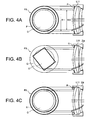
- Figs. 4A, 4B and 4C are diagrams each showing specific configuration of a shading member of the imaging apparatus according to Example 1.
- the shield member FS according to Example 1 is constructed by applying shield paint P on the periphery of the object side surface of the negative meniscus lens L11 forming a circular aperture portion O having an inner diameter ⁇ 1.
- a shield member FS according to the present application is not limited to this, any other configurations as shown in Fig. 4B and 4C may be used.
- a plate-like shield member Q having an aperture portion with rectangular shape projecting an external shape of effective pixels of the solid-state imaging device 7 onto the object side lens surface of the negative meniscus lens L11 may be disposed as the shield member FS in such a manner that the shield member Q is disposed inside of the lens barrel 2a holding the high zoom ratio zoom lens system, and comes in contact with the lens surface. With this configuration, it becomes possible to effectively prevent stray light from entering into the high zoom ratio zoom lens system.
- Example 1 as shown in Fig. 4C , when the inner diameter of an annular member R, such as a so-called retaining ring, which is screwed and fixed into the lens barrel 2a so as to fix the position of the negative meniscus lens L11 in a direction of the optical axis is made to be ⁇ 1, it becomes possible to make the annular member R function as a shield member FS.
- an annular member R having a high retaining ability is suitable for a large diameter lens.
- f denotes a focal length
- FNO denotes an f-number
- ⁇ 0 denoted an effective diameter of the negative meniscus lens L11
- ⁇ 1 denotes an inner diameter of the aperture portion O of the shield member FS, which is the maximum effective diameter of the negative meniscus lens L11 upon carrying out vibration reduction
- IH denotes a diagonal length of the solid-state imaging device from the center to a corner
- L denotes a total lens length of the high zoom ratio zoom lens system in a wide-angle end state
- ⁇ hw denotes the maximum moving amount of the solid-state imaging device 7 in the wide-angle end state
- ⁇ ht denotes the maximum moving amount of the solid-state imaging device 7 in the telephoto end state.
- surface shows the lens surface number counted in order from the object side
- r shows a radius of curvature
- d shows a distance to the next surface
- Bf denotes back focal length.
- E-n denotes " ⁇ 10 -n ".
- y denotes a vertical height from the optical axis
- X(y) denotes a sag amount which is a distance along the optical axis from the tangent surface at the vertex of the aspherical surface to the aspherical surface at the vertical height y from the optical axis
- r denotes a radius of curvature of a reference sphere
- ⁇ denotes a conical coefficient
- Cn denotes an aspherical coefficient of n-th order
- f denotes a focal length
- ⁇ denotes an imaging magnification
- D0 denotes a distance between an object and the object side surface of the negative meniscus lens L11 in the first lens group G1 (a photo-taking distance)
- Bf denotes a back focal length
- TL denotes a total lens length.
- mm is generally used for the unit of length such as the focal length, the radius of curvature and the like.
- the unit is not necessarily to be limited to "mm", and any other suitable unit can be used.
- Figs. 6A, 6B and 6C are graphs showing various aberrations of the high zoom ratio zoom lens system according to Example 1 upon focusing on infinity, in which Fig. 2A is in a wide-angle end state, Fig. 2B is in an intermediate focal length state, and Fig. 2C is in a telephoto end state.
- FNO denotes an f-number
- NA denotes a numerical aperture
- Y denotes an image height.
- the zoom lens system according to Example 1 shows superb optical performance as a result of good corrections to various aberrations in the wide-angle end state, in the intermediate focal length state, and in the telephoto end state upon focusing on infinity and on a close object.
- Example 2 The basic configuration of an imaging apparatus according to Example 2 is the same as Example 1, so that the duplicated explanations are omitted, and a high zoom ratio zoom lens system according to Example 2, which has different configuration from that of Example 1, is precisely explained below.
- Fig. 8 is diagram showing the high zoom ratio zoom lens system attached to the imaging apparatus according to Example 2 upon focusing on infinity in a wide-angle end state W, in an intermediate focal length state M, and in a telephoto end state T.
- the high zoom ratio zoom lens system according to Example 2 is composed of, in order from an object, a first lens group G1 having positive refractive power, a second lens group G2 having negative refractive power, an aperture stop S, a third lens group G3 having positive refractive power, a fourth lens group G4 having positive refractive power, a fifth lens group having positive refractive power, an optical low-pass filter LF, and a cover glass CG for a solid-state imaging device 7.
- the first lens group G1 is composed of, in order from the object, a cemented positive lens constructed by a negative meniscus lens L11 having a convex surface facing the object cemented with a positive meniscus lens L12 having a convex surface facing the object, and a positive meniscus lens L13 having a convex surface facing the object.
- the second lens group G2 is composed of, in order from the object, a negative meniscus lens L21 having a convex surface facing the object, and a cemented negative lens constructed by a double concave negative lens L22 cemented with a positive meniscus lens L23 having a convex surface facing the object.
- the third lens group G3 is composed of, in order from the object, a double convex positive lens L31, and a negative meniscus lens L32 having a concave surface facing the object.
- the fourth lens group G4 is composed of, in order from the object, a front group G4F having positive refractive power, and a rear group G4R having negative refractive power.
- the front group G4F is composed of a double convex positive lens L41 having an aspherical surface facing the image.
- the rear group G4R is composed of a cemented negative lens constructed by, in order from the object, a double convex positive lens L42 cemented with a double concave negative lens L43.
- the fifth lens group G5 is composed of a positive meniscus lens L51 having a convex surface facing the object.
- the first lens group G1 upon zooming from a wide-angle end state to a telephoto end state, the first lens group G1 is moved to the object, the second lens group G2 is moved at first to the image and then to the object, which has a zoom trajectory having a concave shape facing the object, the third lens group G3 is moved to the object, and the fourth lens group G4 is moved to the object.
- the aperture stop S is moved in a body with the third lens group G3.
- the fifth lens group G5 that is fixed upon zooming is move to the object.
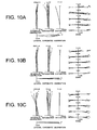
- Figs. 10A, 10B and 10C are graphs showing various aberrations of the high zoom ratio zoom lens system according to Example 2 upon focusing on infinity, in which Fig. 10A is in a wide-angle end state, Fig. 10B is in an intermediate focal length state, and Fig. 10C is in a telephoto end state.
- the zoom lens system according to Example 2 shows superb optical performance as a result of good corrections to various aberrations in the wide-angle end state, in the intermediate focal length state, and in the telephoto end state upon focusing on infinity and on a close object.
- any lens surface composing the high zoom ratio zoom lens system according to the present application may be an aspherical surface.
- the aspherical surface may be fabricated by a fine grinding process, a glass molding process that a glass material is formed into an aspherical shape by a mold, or a compound type process that a resin material is formed into an aspherical shape on a glass surface.
- An antireflection coating having high transmittance over a broad wavelength range may be applied to each lens surface of the high zoom ratio zoom lens system according to the present application to reduce flare or ghost images, so that high optical performance with a high contrast can be attained.
- each Example only shows an specific example of a high zoom ratio zoom lens system, so that the present invention is not limited to such Examples.
- an imaging apparatus an imaging method, and a high zoom ratio zoom lens carrying out vibration reduction by moving an imaging device in a direction substantially perpendicular to an optical axis, capable of efficiently using effective pixels of the solid-state imaging device, and capable of securing an excellent peripheral light quantity ratio of an object image even upon carrying out vibration reduction.
- a high zoom ration zoom lens system is suitable for an electronic still camera, and the like, capable of realizing a half angle of view of 4 degrees or less in a telephoto end state, an f-number in the telephoto end state of 6 or less, a zoom ratio of about 10, and compactness in the diameter of the lens barrel.
Landscapes
- Physics & Mathematics (AREA)
- General Physics & Mathematics (AREA)
- Optics & Photonics (AREA)
- Engineering & Computer Science (AREA)
- Multimedia (AREA)
- Signal Processing (AREA)
- Lenses (AREA)
- Transforming Light Signals Into Electric Signals (AREA)
Claims (13)
- Abbildungsgerät (1), umfassend:ein Zoomobjektivsystem (2) mit großem Zoomfaktor, umfassend, der Reihe nach von einer Objektseite aus, eine erste Linsengruppe (G1), die eine positive Brechkraft aufweist, eine zweite Linsengruppe (G2), die eine negative Brechkraft aufweist, eine dritte Linsengruppe (G3), eine vierte Linsengruppe (G4) und eine fünfte Linsengruppe (G5) zum Zoomen vom Weitwinkel-Endzustand zum Teleobjektiv-Endzustand, wobei die erste Linsengruppe (G1), die zweite Linsengruppe (G2), die dritte Linsengruppe (G3) und die vierte Linsengruppe (G4) an der optischen Achse entlang bewegbar sind;eine Festkörper-Abbildungsvorrichtung (7), die angeordnet ist, um das Bild aufzunehmen, das von dem Zoomobjektivsystem (2) mit großem Zoomfaktor gebildet wird;ein Erfassungsorgan (9), das angeordnet ist, um die Änderung der Position des Bildes zu erfassen;ein Antriebsorgan (10), das angeordnet ist, um die Festkörper-Abbildungsvorrichtung (7) in einer Richtung zu bewegen, die zu der optischen Achse im Wesentlichen rechtwinklig ist;ein Steuerorgan (11), das angeordnet ist, um das Antriebsorgan (10) zu steuern, um die Änderung der Position des Objektbildes zu korrigieren; undein Abschirmorgan (FS) mit einem Aperturabschnitt (O), der angeordnet ist, um ein Strahlenbündel zu begrenzen, das auf den Rand der am weitesten objektseitigen Linse in der ersten Linsengruppe (G1) des Zoomobjektivsystems (2) mit großem Zoomfaktor einfällt; undwobei der folgende boolesche Ausdruck erfüllt ist:

- Abbildungsgerät (1) nach Anspruch 1, wobei die dritte Linsengruppe (G3) eine positive Brechkraft aufweist, die vierte Linsengruppe (G4) eine positive Brechkraft aufweist, und die fünfte Linsengruppe (G5) eine positive Brechkraft aufweist.
- Abbildungsgerät (1) nach Anspruch 1 oder 2, wobei der folgende boolesche Ausdruck erfüllt ist:

- Abbildungsgerät (1) nach Anspruch 1, 2 oder 3, wobei die vierte Linsengruppe (G4), der Reihe nach von der Objektseite aus, aus einer vorderen Gruppe (GF), die eine positive Brechkraft aufweist, und einer hinteren Gruppe (G4R), die eine negative Brechkraft aufweist, besteht und der folgende boolesche Ausdruck erfüllt ist:

- Abbildungsgerät nach einem der vorhergehenden Ansprüche, wobei der Aperturabschnitt (O) in dem Abschirmorgan (FS) eine kreisförmige Apertur ist.
- Abbildungsgerät nach einem der Ansprüche 1 bis 5, wobei der Aperturabschnitt in dem Abschirmorgan eine rechteckige Apertur ist.
- Abbildungsgerät (1) nach einem der vorhergehenden Ansprüche, wobei der folgende boolesche Ausdruck erfüllt ist:
- Abbildungsgerät (1) nach einem der vorhergehenden Ansprüche, wobei das Abschirmorgan (FS) dadurch gebildet wird, dass Abschirmfarbe auf der am weitesten objektseitigen Linsenfläche der ersten Linsengruppe (G1) aufgetragen wird.
- Abbildungsgerät (1) nach einem der Ansprüche 1 bis 7, wobei das Abschirmorgan (FS) ein plättchenartiges Organ ist, das in der Nähe der am weitesten objektseitigen Linsenfläche der ersten Linsengruppe (G1) in dem Zoomobjektivsystem (2) mit großem Zoomfaktor angeordnet ist.
- Abbildungsgerät (1) nach einem der Ansprüche 1 bis 7, wobei das Abschirmorgan in einem Körper mit einem Linsenbefestigungsorgan gebildet ist, um die am weitesten objektseitige Linse der ersten Linsengruppe in dem Zoomobjektivsystem mit großem Zoomfaktor zu befestigen.
- Abbildungsgerät (1) nach einem der vorhergehenden Ansprüche, wobei das Zoomobjektivsystem (2) mit großem Zoomfaktor die Fokussierung ausführt, indem es die fünfte Linsengruppe (G5) an der optischen Achse entlang bewegt.
- Abbildungsverfahren zum Aufnehmen eines Bildes, das durch ein Zoomobjektivsystem (2) mit großem Zoomfaktor gebildet wird, mittels einer Festkörper-Abbildungsvorrichtung (7) durch das Erfassen einer Änderung der Position des Bildes und das Bewegen der Festkörper-Abbildungsvorrichtung (7) in einer Richtung, die zu der optischen Achse im Wesentlichen rechtwinklig ist, um die Änderung der Position des Bildes zu korrigieren, wobei das Abbildungsverfahren folgende Schritte umfasst:Bereitstellen des Zoomobjektivsystems (2) mit großem Zoomfaktor, das der Reihe nach von der Objektseite aus eine erste Linsengruppe (G1), die eine positive Brechkraft aufweist, eine zweite Linsengruppe (G2), die eine negative Brechkraft aufweist, eine dritte Linsengruppe (G3), eine vierte Linsengruppe (G4) und eine fünfte Linsengruppe (G5) aufweist, wobei beim Zoomen von dem Weitwinkel-Endzustand zum Teleobjektiv-Endzustand die erste Linsengruppe (G1), die zweite Linsengruppe (G2), die dritte Linsengruppe (G3) und die vierte Linsengruppe (G4) an der optischen Achse entlang bewegt werden;Begrenzen eines Strahlenbündels, das auf den Rand der am weitesten objektseitigen Linse in der ersten Linsengruppe (G1) des Zoomobjektivsystems (2) mit großem Zoomfaktor einfällt, durch ein Abschirmorgan (FS) mit einem Aperturabschnitt (O); undErfüllen des folgenden booleschen Ausdrucks:

- Abbildungsverfahren nach Anspruch 12, wobei das Abbildungsgerät nach einem der Ansprüche 2 bis 11 ist.
Applications Claiming Priority (2)
| Application Number | Priority Date | Filing Date | Title |
|---|---|---|---|
| JP2006099295 | 2006-03-31 | ||
| PCT/JP2007/053696 WO2007113952A1 (ja) | 2006-03-31 | 2007-02-21 | 撮像装置、撮像方法、高変倍ズームレンズ |
Publications (3)
| Publication Number | Publication Date |
|---|---|
| EP2003479A1 EP2003479A1 (de) | 2008-12-17 |
| EP2003479A4 EP2003479A4 (de) | 2009-07-15 |
| EP2003479B1 true EP2003479B1 (de) | 2010-12-29 |
Family
ID=38563225
Family Applications (1)
| Application Number | Title | Priority Date | Filing Date |
|---|---|---|---|
| EP07715031A Not-in-force EP2003479B1 (de) | 2006-03-31 | 2007-02-21 | Telezoomobjektiv mit hohem Vergrösserungsverhältnis |
Country Status (7)
| Country | Link |
|---|---|
| US (1) | US7843647B2 (de) |
| EP (1) | EP2003479B1 (de) |
| JP (1) | JP5071380B2 (de) |
| CN (1) | CN101395518B (de) |
| AT (1) | ATE493682T1 (de) |
| DE (1) | DE602007011584D1 (de) |
| WO (1) | WO2007113952A1 (de) |
Families Citing this family (16)
| Publication number | Priority date | Publication date | Assignee | Title |
|---|---|---|---|---|
| JP4813448B2 (ja) * | 2007-11-16 | 2011-11-09 | 富士フイルム株式会社 | 撮像システム、並びにこの撮像システムを備えた撮像装置、携帯端末機器、車載機器、および医療機器 |
| JP2009139697A (ja) * | 2007-12-07 | 2009-06-25 | Fujinon Corp | 撮像システム、この撮像システムを備えた撮像装置、携帯端末機器、車載機器、および医療機器、並びに撮像システムの製造方法 |
| JP5154981B2 (ja) * | 2008-03-10 | 2013-02-27 | オリンパスイメージング株式会社 | ズームレンズを備えた撮像装置 |
| JP5423235B2 (ja) * | 2009-08-20 | 2014-02-19 | ソニー株式会社 | 撮像装置 |
| JP5293716B2 (ja) * | 2010-09-30 | 2013-09-18 | 株式会社ニコン | 交換レンズ、カメラボディおよびカメラシステム |
| JP5734769B2 (ja) * | 2011-06-28 | 2015-06-17 | シャープ株式会社 | 撮像レンズおよび撮像モジュール |
| TWI420143B (zh) * | 2011-07-01 | 2013-12-21 | Asia Optical Co Inc | Zoom lens |
| CN103135195A (zh) * | 2011-12-01 | 2013-06-05 | 佛山普立华科技有限公司 | 变焦镜头以及成像装置 |
| CN103163637A (zh) * | 2011-12-17 | 2013-06-19 | 鸿富锦精密工业(深圳)有限公司 | 变焦镜头 |
| CN103207446A (zh) * | 2013-04-23 | 2013-07-17 | 中国科学院西安光学精密机械研究所 | 一种用于微光探测的光学耦合系统 |
| US9602727B2 (en) * | 2015-03-06 | 2017-03-21 | Panasonic Intellectual Property Management Co., Ltd. | Imaging apparatus and imaging method |
| US10171739B2 (en) * | 2016-03-02 | 2019-01-01 | Panasonic Intellectual Property Management Co., Ltd. | Image pickup device |
| TWI627439B (zh) * | 2017-08-02 | 2018-06-21 | 信泰光學(深圳)有限公司 | 鏡頭裝置 |
| US11209578B2 (en) | 2017-08-02 | 2021-12-28 | Sintai Optical (Shenzhen) Co., Ltd. | Camera device |
| JP7532046B2 (ja) * | 2020-03-03 | 2024-08-13 | キヤノン株式会社 | 撮像装置およびその制御方法、撮像システム |
| CN120178483A (zh) * | 2021-09-23 | 2025-06-20 | 核心光电有限公司 | 大光圈连续变焦折叠长焦摄像头模块及移动装置 |
Family Cites Families (12)
| Publication number | Priority date | Publication date | Assignee | Title |
|---|---|---|---|---|
| JP3153273B2 (ja) | 1991-08-01 | 2001-04-03 | オリンパス光学工業株式会社 | カメラ |
| JPH06160779A (ja) | 1992-11-25 | 1994-06-07 | Canon Inc | 可変頂角プリズム装置を有した防振光学系 |
| JPH06339054A (ja) | 1993-05-31 | 1994-12-06 | Nikon Corp | 変倍撮像装置 |
| US5587739A (en) | 1993-03-26 | 1996-12-24 | Nikon Corporation | Variable magnification image taking device |
| US5579171A (en) | 1993-03-30 | 1996-11-26 | Nikon Corporation | Zoom lens equipped with the image stabilizing function |
| JPH06289298A (ja) * | 1993-03-30 | 1994-10-18 | Nikon Corp | 防振機能を備えたズームレンズ |
| JP2001337272A (ja) | 2000-05-26 | 2001-12-07 | Matsushita Electric Ind Co Ltd | 手振れ補正機能搭載ズームレンズ及びそれを用いたビデオカメラ |
| JP4288408B2 (ja) * | 2003-02-20 | 2009-07-01 | 株式会社ニコン | 像シフト可能なズームレンズ |
| JP4606105B2 (ja) * | 2004-09-24 | 2011-01-05 | Hoya株式会社 | 像ブレ補正装置 |
| JP4774710B2 (ja) | 2004-09-30 | 2011-09-14 | 株式会社ニコン | ズームレンズ |
| JP2007033879A (ja) * | 2005-07-27 | 2007-02-08 | Sony Corp | 撮像レンズ装置及び撮像装置 |
| US20080297901A1 (en) * | 2007-05-29 | 2008-12-04 | Nikon Corporation | Zoom lens system, optical apparatus, and method for forming an image |
-
2007
- 2007-02-21 WO PCT/JP2007/053696 patent/WO2007113952A1/ja not_active Ceased
- 2007-02-21 EP EP07715031A patent/EP2003479B1/de not_active Not-in-force
- 2007-02-21 DE DE602007011584T patent/DE602007011584D1/de active Active
- 2007-02-21 US US12/160,568 patent/US7843647B2/en active Active
- 2007-02-21 JP JP2008508461A patent/JP5071380B2/ja not_active Expired - Fee Related
- 2007-02-21 CN CN2007800081558A patent/CN101395518B/zh not_active Expired - Fee Related
- 2007-02-21 AT AT07715031T patent/ATE493682T1/de not_active IP Right Cessation
Also Published As
| Publication number | Publication date |
|---|---|
| US7843647B2 (en) | 2010-11-30 |
| WO2007113952A1 (ja) | 2007-10-11 |
| ATE493682T1 (de) | 2011-01-15 |
| CN101395518A (zh) | 2009-03-25 |
| JP5071380B2 (ja) | 2012-11-14 |
| EP2003479A1 (de) | 2008-12-17 |
| CN101395518B (zh) | 2012-01-25 |
| US20100232032A1 (en) | 2010-09-16 |
| DE602007011584D1 (de) | 2011-02-10 |
| EP2003479A4 (de) | 2009-07-15 |
| JPWO2007113952A1 (ja) | 2009-08-13 |
Similar Documents
| Publication | Publication Date | Title |
|---|---|---|
| EP2003479B1 (de) | Telezoomobjektiv mit hohem Vergrösserungsverhältnis | |
| EP1881357B1 (de) | Vibrationsbeständiges Telezoomobjektiv mit vier Linsengruppen | |
| EP2071379B1 (de) | Makro-Teleobjektiv mit drei Linsengruppen vom Frontfokus-Typ und Verfahren zu seiner Herstellung | |
| EP2620796B1 (de) | Optisches System und Bildgebungsvorrichtung | |
| EP2397881B1 (de) | Retrofokus Zoomobjektiv mit vier Linsengruppen | |
| EP2360504B1 (de) | Zoomobjektivsystem, optische Vorrichtung und Verfahren zur Herstellung eines Zoomobjektivsystems | |
| US7551367B2 (en) | Wide-angle lens, optical apparatus and method for focusing | |
| EP2045637B1 (de) | Zoomobjektivsystem | |
| EP1998204B1 (de) | Vibrationsbeständiges Telezoomobjektiv mit vier Linsengruppen vom Hinterfokus-Typ | |
| EP2112542A2 (de) | Optisches System, Fokussierungsverfahren und Abbildungsvorrichtung damit | |
| EP1870760A1 (de) | Retrofokus Zoom Objektiv mit vier Linsengruppen | |
| US7940472B2 (en) | Zoom lens and optical apparatus equipped therewith | |
| EP3176621B1 (de) | Optisches system mit variabler leistung, optische vorrichtung und verfahren zur herstellung eines optischen systems mit variabler leistung | |
| EP2020613A2 (de) | Optisches System | |
| JP4817551B2 (ja) | ズームレンズ | |
| US8040615B2 (en) | Zoom lens and optical apparatus equipped therewith | |
| JP5839062B2 (ja) | ズームレンズ、光学装置 | |
| CN108604003A (zh) | 变焦镜头、光学设备以及变焦镜头的制造方法 | |
| JP2015172695A (ja) | ズームレンズ、光学装置、ズームレンズの製造方法 |
Legal Events
| Date | Code | Title | Description |
|---|---|---|---|
| PUAI | Public reference made under article 153(3) epc to a published international application that has entered the european phase |
Free format text: ORIGINAL CODE: 0009012 |
|
| 17P | Request for examination filed |
Effective date: 20080711 |
|
| AK | Designated contracting states |
Kind code of ref document: A1 Designated state(s): AT BE BG CH CY CZ DE DK EE ES FI FR GB GR HU IE IS IT LI LT LU LV MC NL PL PT RO SE SI SK TR |
|
| A4 | Supplementary search report drawn up and despatched |
Effective date: 20090617 |
|
| RIC1 | Information provided on ipc code assigned before grant |
Ipc: G02B 15/173 20060101AFI20090610BHEP Ipc: H04N 5/232 20060101ALI20090610BHEP Ipc: G03B 17/02 20060101ALI20090610BHEP Ipc: G02B 7/02 20060101ALN20090610BHEP Ipc: G02B 27/64 20060101ALI20090610BHEP |
|
| 17Q | First examination report despatched |
Effective date: 20090917 |
|
| RTI1 | Title (correction) |
Free format text: ZOOM LENS OF THE TELEPHOTO TYPE WITH A HIGH ZOOM RATIO |
|
| GRAP | Despatch of communication of intention to grant a patent |
Free format text: ORIGINAL CODE: EPIDOSNIGR1 |
|
| RAP1 | Party data changed (applicant data changed or rights of an application transferred) |
Owner name: NIKON CORPORATION |
|
| GRAS | Grant fee paid |
Free format text: ORIGINAL CODE: EPIDOSNIGR3 |
|
| GRAA | (expected) grant |
Free format text: ORIGINAL CODE: 0009210 |
|
| AK | Designated contracting states |
Kind code of ref document: B1 Designated state(s): AT BE BG CH CY CZ DE DK EE ES FI FR GB GR HU IE IS IT LI LT LU LV MC NL PL PT RO SE SI SK TR |
|
| REG | Reference to a national code |
Ref country code: GB Ref legal event code: FG4D |
|
| REG | Reference to a national code |
Ref country code: CH Ref legal event code: EP |
|
| RIN2 | Information on inventor provided after grant (corrected) |
Inventor name: SATO, SUSUMU |
|
| REG | Reference to a national code |
Ref country code: IE Ref legal event code: FG4D |
|
| REF | Corresponds to: |
Ref document number: 602007011584 Country of ref document: DE Date of ref document: 20110210 Kind code of ref document: P |
|
| REG | Reference to a national code |
Ref country code: DE Ref legal event code: R096 Ref document number: 602007011584 Country of ref document: DE Effective date: 20110210 |
|
| REG | Reference to a national code |
Ref country code: NL Ref legal event code: VDEP Effective date: 20101229 |
|
| PG25 | Lapsed in a contracting state [announced via postgrant information from national office to epo] |
Ref country code: LT Free format text: LAPSE BECAUSE OF FAILURE TO SUBMIT A TRANSLATION OF THE DESCRIPTION OR TO PAY THE FEE WITHIN THE PRESCRIBED TIME-LIMIT Effective date: 20101229 |
|
| LTIE | Lt: invalidation of european patent or patent extension |
Effective date: 20101229 |
|
| PG25 | Lapsed in a contracting state [announced via postgrant information from national office to epo] |
Ref country code: CY Free format text: LAPSE BECAUSE OF FAILURE TO SUBMIT A TRANSLATION OF THE DESCRIPTION OR TO PAY THE FEE WITHIN THE PRESCRIBED TIME-LIMIT Effective date: 20101229 Ref country code: AT Free format text: LAPSE BECAUSE OF FAILURE TO SUBMIT A TRANSLATION OF THE DESCRIPTION OR TO PAY THE FEE WITHIN THE PRESCRIBED TIME-LIMIT Effective date: 20101229 Ref country code: SI Free format text: LAPSE BECAUSE OF FAILURE TO SUBMIT A TRANSLATION OF THE DESCRIPTION OR TO PAY THE FEE WITHIN THE PRESCRIBED TIME-LIMIT Effective date: 20101229 Ref country code: LV Free format text: LAPSE BECAUSE OF FAILURE TO SUBMIT A TRANSLATION OF THE DESCRIPTION OR TO PAY THE FEE WITHIN THE PRESCRIBED TIME-LIMIT Effective date: 20101229 Ref country code: SE Free format text: LAPSE BECAUSE OF FAILURE TO SUBMIT A TRANSLATION OF THE DESCRIPTION OR TO PAY THE FEE WITHIN THE PRESCRIBED TIME-LIMIT Effective date: 20101229 Ref country code: FI Free format text: LAPSE BECAUSE OF FAILURE TO SUBMIT A TRANSLATION OF THE DESCRIPTION OR TO PAY THE FEE WITHIN THE PRESCRIBED TIME-LIMIT Effective date: 20101229 Ref country code: BG Free format text: LAPSE BECAUSE OF FAILURE TO SUBMIT A TRANSLATION OF THE DESCRIPTION OR TO PAY THE FEE WITHIN THE PRESCRIBED TIME-LIMIT Effective date: 20110329 |
|
| PG25 | Lapsed in a contracting state [announced via postgrant information from national office to epo] |
Ref country code: BE Free format text: LAPSE BECAUSE OF FAILURE TO SUBMIT A TRANSLATION OF THE DESCRIPTION OR TO PAY THE FEE WITHIN THE PRESCRIBED TIME-LIMIT Effective date: 20101229 Ref country code: ES Free format text: LAPSE BECAUSE OF FAILURE TO SUBMIT A TRANSLATION OF THE DESCRIPTION OR TO PAY THE FEE WITHIN THE PRESCRIBED TIME-LIMIT Effective date: 20110409 Ref country code: IS Free format text: LAPSE BECAUSE OF FAILURE TO SUBMIT A TRANSLATION OF THE DESCRIPTION OR TO PAY THE FEE WITHIN THE PRESCRIBED TIME-LIMIT Effective date: 20110429 Ref country code: PT Free format text: LAPSE BECAUSE OF FAILURE TO SUBMIT A TRANSLATION OF THE DESCRIPTION OR TO PAY THE FEE WITHIN THE PRESCRIBED TIME-LIMIT Effective date: 20110429 Ref country code: EE Free format text: LAPSE BECAUSE OF FAILURE TO SUBMIT A TRANSLATION OF THE DESCRIPTION OR TO PAY THE FEE WITHIN THE PRESCRIBED TIME-LIMIT Effective date: 20101229 Ref country code: GR Free format text: LAPSE BECAUSE OF FAILURE TO SUBMIT A TRANSLATION OF THE DESCRIPTION OR TO PAY THE FEE WITHIN THE PRESCRIBED TIME-LIMIT Effective date: 20110330 Ref country code: CZ Free format text: LAPSE BECAUSE OF FAILURE TO SUBMIT A TRANSLATION OF THE DESCRIPTION OR TO PAY THE FEE WITHIN THE PRESCRIBED TIME-LIMIT Effective date: 20101229 |
|
| PG25 | Lapsed in a contracting state [announced via postgrant information from national office to epo] |
Ref country code: SK Free format text: LAPSE BECAUSE OF FAILURE TO SUBMIT A TRANSLATION OF THE DESCRIPTION OR TO PAY THE FEE WITHIN THE PRESCRIBED TIME-LIMIT Effective date: 20101229 Ref country code: RO Free format text: LAPSE BECAUSE OF FAILURE TO SUBMIT A TRANSLATION OF THE DESCRIPTION OR TO PAY THE FEE WITHIN THE PRESCRIBED TIME-LIMIT Effective date: 20101229 Ref country code: NL Free format text: LAPSE BECAUSE OF FAILURE TO SUBMIT A TRANSLATION OF THE DESCRIPTION OR TO PAY THE FEE WITHIN THE PRESCRIBED TIME-LIMIT Effective date: 20101229 Ref country code: PL Free format text: LAPSE BECAUSE OF FAILURE TO SUBMIT A TRANSLATION OF THE DESCRIPTION OR TO PAY THE FEE WITHIN THE PRESCRIBED TIME-LIMIT Effective date: 20101229 |
|
| PG25 | Lapsed in a contracting state [announced via postgrant information from national office to epo] |
Ref country code: MC Free format text: LAPSE BECAUSE OF NON-PAYMENT OF DUE FEES Effective date: 20110228 |
|
| REG | Reference to a national code |
Ref country code: CH Ref legal event code: PL |
|
| PG25 | Lapsed in a contracting state [announced via postgrant information from national office to epo] |
Ref country code: DK Free format text: LAPSE BECAUSE OF FAILURE TO SUBMIT A TRANSLATION OF THE DESCRIPTION OR TO PAY THE FEE WITHIN THE PRESCRIBED TIME-LIMIT Effective date: 20101229 Ref country code: CH Free format text: LAPSE BECAUSE OF NON-PAYMENT OF DUE FEES Effective date: 20110228 Ref country code: LI Free format text: LAPSE BECAUSE OF NON-PAYMENT OF DUE FEES Effective date: 20110228 |
|
| PLBE | No opposition filed within time limit |
Free format text: ORIGINAL CODE: 0009261 |
|
| STAA | Information on the status of an ep patent application or granted ep patent |
Free format text: STATUS: NO OPPOSITION FILED WITHIN TIME LIMIT |
|
| REG | Reference to a national code |
Ref country code: IE Ref legal event code: MM4A |
|
| 26N | No opposition filed |
Effective date: 20110930 |
|
| REG | Reference to a national code |
Ref country code: DE Ref legal event code: R097 Ref document number: 602007011584 Country of ref document: DE Effective date: 20110930 |
|
| PG25 | Lapsed in a contracting state [announced via postgrant information from national office to epo] |
Ref country code: IE Free format text: LAPSE BECAUSE OF NON-PAYMENT OF DUE FEES Effective date: 20110221 |
|
| PG25 | Lapsed in a contracting state [announced via postgrant information from national office to epo] |
Ref country code: IT Free format text: LAPSE BECAUSE OF FAILURE TO SUBMIT A TRANSLATION OF THE DESCRIPTION OR TO PAY THE FEE WITHIN THE PRESCRIBED TIME-LIMIT Effective date: 20101229 |
|
| PG25 | Lapsed in a contracting state [announced via postgrant information from national office to epo] |
Ref country code: LU Free format text: LAPSE BECAUSE OF NON-PAYMENT OF DUE FEES Effective date: 20110221 |
|
| PG25 | Lapsed in a contracting state [announced via postgrant information from national office to epo] |
Ref country code: TR Free format text: LAPSE BECAUSE OF FAILURE TO SUBMIT A TRANSLATION OF THE DESCRIPTION OR TO PAY THE FEE WITHIN THE PRESCRIBED TIME-LIMIT Effective date: 20101229 |
|
| PG25 | Lapsed in a contracting state [announced via postgrant information from national office to epo] |
Ref country code: HU Free format text: LAPSE BECAUSE OF FAILURE TO SUBMIT A TRANSLATION OF THE DESCRIPTION OR TO PAY THE FEE WITHIN THE PRESCRIBED TIME-LIMIT Effective date: 20101229 |
|
| REG | Reference to a national code |
Ref country code: FR Ref legal event code: PLFP Year of fee payment: 10 |
|
| REG | Reference to a national code |
Ref country code: FR Ref legal event code: PLFP Year of fee payment: 11 |
|
| REG | Reference to a national code |
Ref country code: FR Ref legal event code: PLFP Year of fee payment: 12 |
|
| PGFP | Annual fee paid to national office [announced via postgrant information from national office to epo] |
Ref country code: DE Payment date: 20200211 Year of fee payment: 14 Ref country code: GB Payment date: 20200212 Year of fee payment: 14 |
|
| PGFP | Annual fee paid to national office [announced via postgrant information from national office to epo] |
Ref country code: FR Payment date: 20200113 Year of fee payment: 14 |
|
| REG | Reference to a national code |
Ref country code: DE Ref legal event code: R119 Ref document number: 602007011584 Country of ref document: DE |
|
| GBPC | Gb: european patent ceased through non-payment of renewal fee |
Effective date: 20210221 |
|
| PG25 | Lapsed in a contracting state [announced via postgrant information from national office to epo] |
Ref country code: GB Free format text: LAPSE BECAUSE OF NON-PAYMENT OF DUE FEES Effective date: 20210221 Ref country code: FR Free format text: LAPSE BECAUSE OF NON-PAYMENT OF DUE FEES Effective date: 20210228 Ref country code: DE Free format text: LAPSE BECAUSE OF NON-PAYMENT OF DUE FEES Effective date: 20210901 |