EP2003533B1 - Vorrichtung zur Leistungssteuerung in einer elektronischen Vorrichtung - Google Patents
Vorrichtung zur Leistungssteuerung in einer elektronischen Vorrichtung Download PDFInfo
- Publication number
- EP2003533B1 EP2003533B1 EP08165796A EP08165796A EP2003533B1 EP 2003533 B1 EP2003533 B1 EP 2003533B1 EP 08165796 A EP08165796 A EP 08165796A EP 08165796 A EP08165796 A EP 08165796A EP 2003533 B1 EP2003533 B1 EP 2003533B1
- Authority
- EP
- European Patent Office
- Prior art keywords
- function
- electronic device
- power
- battery
- flash
- Prior art date
- Legal status (The legal status is an assumption and is not a legal conclusion. Google has not performed a legal analysis and makes no representation as to the accuracy of the status listed.)
- Active
Links
Images


Classifications
-
- G—PHYSICS
- G06—COMPUTING OR CALCULATING; COUNTING
- G06F—ELECTRIC DIGITAL DATA PROCESSING
- G06F1/00—Details not covered by groups G06F3/00 - G06F13/00 and G06F21/00
- G06F1/26—Power supply means, e.g. regulation thereof
- G06F1/32—Means for saving power
- G06F1/3203—Power management, i.e. event-based initiation of a power-saving mode
-
- H—ELECTRICITY
- H04—ELECTRIC COMMUNICATION TECHNIQUE
- H04N—PICTORIAL COMMUNICATION, e.g. TELEVISION
- H04N23/00—Cameras or camera modules comprising electronic image sensors; Control thereof
- H04N23/60—Control of cameras or camera modules
- H04N23/65—Control of camera operation in relation to power supply
- H04N23/651—Control of camera operation in relation to power supply for reducing power consumption by affecting camera operations, e.g. sleep mode, hibernation mode or power off of selective parts of the camera
-
- H—ELECTRICITY
- H04—ELECTRIC COMMUNICATION TECHNIQUE
- H04N—PICTORIAL COMMUNICATION, e.g. TELEVISION
- H04N23/00—Cameras or camera modules comprising electronic image sensors; Control thereof
- H04N23/70—Circuitry for compensating brightness variation in the scene
- H04N23/74—Circuitry for compensating brightness variation in the scene by influencing the scene brightness using illuminating means
Definitions
- the present application relates generally to electronic devices and more particularly relates to a method and electronic device for power management in an electronic device, such as a multi-function portable electronic device that includes a camera flash or the like.
- PDA personal digital assistant
- Blackberry TM from Research in Motion of Waterloo, Canada being an example of such a device.
- wireless voice functionality music and video players into such devices.
- cameras are being incorporated into such devices.
- One particular vexing problem is the camera flash.
- the battery ESR may be too high to support a camera flash.
- the camera flash is a high drain on the battery for a long period of time. It is not uncommon for a camera flash to draw up to about one ampere (Amp) of power from the battery for up to about eighty milliseconds (ms). This draw can cause battery "droop". In such cases the battery droop may be such to trip battery supervisory circuits, causing the handset to reset or go into sleep mode. This can be a frustrating experience for the user.
- Amp ampere
- ms milliseconds
- US-A-5963255 describes a system and method for managing utilization of a battery, particularly in the context of a digital camera.
- the camera is configured to monitor the voltage level of the camera, and, if the voltage falls below a predetermined threshold, then the power manager configures the camera into a lower power consumption state.
- the use of multiple power consumption states does not address the problem that can be caused by a flash or other high-intensity component whereby a large margin of battery reserve may be needed, and difficult to determine, as the momentary conditions of the battery vary.
- US-A- 5845142 describes a portable terminal that has a judging means for forecasting the power that is necessary for conducting a communication, and a means for measuring current residual battery capacity. The communication will be allowed or suppressed based on the forecast of power and the amount of residual battery capacity. Again, this disclosure does not address the problem that can be caused by a flash or other high-intensity component whereby a large margin of battery reserve may be needed, and difficult to determine, as the momentary conditions of the battery vary.
- US-A-4290677 describes an apparatus for checking the operational status of an electronic strobe unit's battery under load conditions.
- the intent in this disclosure is to ultimately provide an indicator that provides a visual indication of the charge condition of the battery. Again, it does not address the problem that can be caused by a flash or other high-intensity component whereby a large margin of battery reserve may be needed, and difficult to determine, as the momentary conditions of the battery vary.
- An aspect of the invention provides an electronic device comprising: a power supply; a supervisor circuit connected to said power supply for disabling all or a portion of functions of said electronic device if a first level of power from said power supply falls below a predefined threshold, a radio, said supervisor circuit configured to disable said radio when said power supply falls below 3.4 Volts for at least fire milliseconds; a processor connected to said power supply and said supervisor circuit; said processor configured to receive a request via an input device for a function to be performed by said electronic device; an output device connected to said power supply, said processor, and said supervisor circuit, said output device configured to perform a function that draws power from said power supply; said processor being configured to perform the steps of: performing a pre-function test; said pre-function test based on said function and selected to consume less power than said function and also selected to not cause the first level of power to fall below said predefined threshold; determining a second level of power to said device as a consequence of performing said pre-function test; and, if said second level of power meets at
- the device may be permitted to perform an alternative function that consumes less power than the function. If the function is a camera flash used at full power then the alternative function can be the camera flash used at less than full power.
- the alternative function can be chosen to consume a third level of power that is greater than the predetermined threshold and differs from the predetermined threshold by a value that approaches zero. In other words the third level of power is chosen to maximize the amount of power available to the alternative function, but without crossing the predetermined threshold.
- the output device can be a camera flash.
- the flash can be activated according to the function for a period of about eighty milliseconds and draws power of about one ampere.
- the flash can be activated according to the pre-function test for a period of about two milliseconds so as to draw power of about one ampere.
- the processor can be operable to generate an output signal indicating that there is insufficient power to perform the function.
- the power supply can be a rechargeable battery housed within the electronic device.
- the first level and the second level of power can be measured using one or more of battery voltage, battery amperage, battery equivalent series resistance, and battery temperature.
- the processor can be configured to measure the battery level after performing the pre-function test.
- the processor can be configured to measure the battery level once before and once after performing the pre-function test.
- the processor can be configured to measure the battery level throughout the performance of the pre-function test.
- the processor can be further configured to, after preventing the electronic device from performing the function, permit the output device to perform an alternative function that consumes less power than the function.
- the alternative function can be the camera flash used at less than full power.
- the alternative function can be chosen to consume a third level of power that is greater than the predetermined threshold and differs from the predetermined threshold by a value that approaches zero.
- the supervisor circuit may be configured to enter said electronic device into a sleep mode when said power supply falls below 3.1 Volts for at least three milliseconds.
- an electronic device in accordance with claim 1.
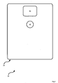
- Device 30 includes a housing 34 that frames an input device in the form of a keyboard 38 and an output device in the form of a display 42.
- device 30 includes at least the functionality of a wireless email paging device and a user of device 30 can interact with keyboard 38 and display 42 to send and receive email messages.
- device 30 is simplified for purposes of explanation, and that in other embodiments device 30 can include, and typically would include additional functionality and include input and output devices accordingly.
- Such other functionality can include voice telephony, music player, audio recording and video player.
- other input devices can include microphones, and other output devices can include speakers.
- Device 30 can also be equipped with Bluetooth TM (or equivalent technology) which acts as a wireless conduit for such input and output device.
- device 30 can include any combination of functions.
- device 30 also includes a camera. Referring now to Figure 2 , a rear view of device 30 is shown. Device 30 thus also includes an additional input device in the form of a camera lens 46 and an additional output device in the form of a flash 50. Those skilled in the art will recognize that lens 46 is also associated with an array of light-sensitive transducers such as an array of charge coupled devices (CCD) which actually create an electronic signal of the image captured via lens 46.
- CCD charge coupled devices
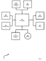
- Device 30 thus includes a processor 54 which interconnects the input devices of device 30 (i.e. keyboard 38 and camera lens 46) and the output devices of device 30 (i.e. display 42 and flash 50).
- Processor 54 is also connected to a persistent storage device 58.
- Persistent storage device 58 can be implemented using flash memory or the like, and/or can include other programmable read only memory (“PROM”) technology and/or can include read only memory (“ROM”) technology.
- Device 30 also includes a wireless radio 62 disposed within housing 34 that connects wirelessly to one of a network of base stations to provide the wireless email functionality of device 30.
- Device 30 also includes a battery 66 which is typically rechargeable and provides power to the components of device 30.
- battery 66 is a lithium battery having an operating voltage of between about 3.0 Volts minimum to about 4.2 Volts maximum.
- battery 66 is only shown connected to processor 54, but it will be understood that battery 66 is connected to any component (e.g. the CCD associated lens 46, radio 62, display 42 and flash 50) within device 30 that needs power to operate.
- flash 50 is a high-intensity component that can cause significant battery drain. As an example, for device 30 it will be assumed that flash 50 draws about one ampere of power for about eighty milliseconds during a single picture-taking flash.
- Device 30 also includes a supervisor circuit 70 that is connected to battery 66 and processor 54.
- Supervisor circuit 70 is operable to monitor the life of battery 66 and depending on the life of battery 66, supervisor circuit 70 can disable various components that draw power and/or cause device 30 to enter sleep mode and/or turn-off device 30 altogether.
- Supervisor circuit 70 is shown as a separate hardware component within device 30, but it should be understood that can simply be implemented as a software process that executes on processor 54.
- supervisor circuit 70 can be implemented as part of a larger analog power-management integrated circuit, such as the TPS65800 power management integrated circuit ("PMIC") from Texas Instruments Incorporated, 12500 TI Boulevard, Dallas, TX 75243-4136.) For example, if supervisor circuit 70 determined that the life of battery 66 was below a certain predefined threshold, then supervisor circuit 70 may disable radio 62 and thereby permit device 30 to continue its other functions even though the send-and-receive capability of the wireless email function is disabled.
- PMIC power management integrated circuit
- supervisor circuit 70 can cause device 30 to turn off altogether, but still ensure that enough power remains in battery 66 to ensure that data is not lost in processor 54 and/or persistent storage 58.
- Supervisor circuit 70 can include a variety of parameters associated with the predefined threshold. For purposes of explaining the present embodiment, Table I gives an example of parameters that can be associated with battery 66, where battery 66 is a lithium battery with the characteristics as described above. Table I Parameters of Supervisor Circuit 70 Event Number Voltage Threshold (Volts) Duration (milliseconds) Event 1 3.4 Volts five ms Disable radio 62 2 3.1 Volts three ms Enter sleep mode
- the first column is simply a label for a particular set of parameters.
- the second column voltage threshold, defines a certain voltage level below which an event associated with the event number may be triggered.
- the third column, duration defines a time period whereby if the voltage of battery 66 in the second column falls below the voltage level in the second column for the duration in the third column, then the event in the fourth column will be triggered.
- supervisor circuit 70 will disable radio 62.
- supervisor circuit 70 will cause device 30 to enter sleep mode.
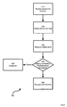
- a method of power management in an electronic device is represented in a flow-chart and indicated generally at 200.
- method 200 will be explained in terms of its performance using device 30 in the context of flash 50. However, it is to be understood that this explanation is not to be construed in a limiting sense and that method 200 can be performed on other devices other than device 30, and/or that method 200 can be varied.
- step 210 a request for a function is received.
- this step can be effected when processor 54 receives an input via keyboard 38 that the user desires to use the flash function in order take a flash picture and capture an image through lens 46.
- a pre-function test is initiated.
- the pre-function test is a pre-flash test.
- the scope of the pre-flash test is chosen based on the parameters of supervisor circuit 70 and flash 50, to be sure that the pre-flash test does not actually exceed the event thresholds of the supervisor circuit 70 and trigger one of the events in Table I.
- the duration of the pre-flash test should be chosen to be much shorter than three milliseconds so that the pre-flash test will not cause supervisor circuit 70 to cause device 30 to enter sleep mode.
- step 220 flash 50 will be fired by processor 54 for a period of two milliseconds such that one ampere of power is drawn by flash 50 from battery 66 for a two millisecond period.
- step 230 at which point the level of battery 66 will be measured.
- the variables used in measuring battery 66 are not particularly limited, and can include any known measurements used for measuring battery 66, for example, voltage level and ESR.
- step 240 a determination is made as to whether the level measured at step 230 is below a predetermined threshold.
- step 240 If, at step 240, it is determined that the battery level is below the predefined threshold, then method 200 advances to step 250 where an exception occurs.
- the exception can simply be a message presented on display 42 to the effect that the battery level is too low in order to use flash 50, and flash 50 can then be disabled so that device 30 continues to otherwise function normally except that flash 50 is not available for use.
- step 240 If, however, at step 240 it is determined that the battery level is not below the predefined threshold, then method 200 advances to step 260 at which point the selected function in device 30 proceeds to operate normally, which in this case is flash 50.
- the selected function in device 30 proceeds to operate normally, which in this case is flash 50.
- flash 50 would operate normally and a flash picture would be taken using the camera features of device 30.
- method 200 can be varied.
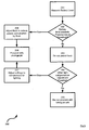
- Figure 5 shows an example of such a variation in the form of flow-chart depicting a method 200a
- Method 200a includes many of the same steps as method 200 and like steps include the same references except followed by the suffix "a".
- method 200a includes step 215a where the battery level is measured once before the pre-function test at step 220a, and then again after the pre-function test at step 230a.
- step 240 is replaced by step 235a, where a change in the battery levels as measured at step 215a and step 230a is examined, and based on this change a determination is made as to whether to proceed, or not, with the full camera flash. For example, if it was determined at step 235a that the voltage of battery 66 dropped a predefined amount then step 235a would advance to step 250a and an exception would be generated.
- a time-varying voltage (and/or amperage and/or other battery level measurement) profile could be captured during the entire performance of step 220a. In turn, that profile can be compared with known profiles that predict whether a full duration flash would exceed the threshold parameters of supervisor circuit 70.
- method 200 and/or method 200a and/or variants thereof can be directly incorporated into supervisor circuit 70.
- FIG. 6 shows an exemplary set of steps that could be used to implement step 250 or step 250a.
- step 251 the battery level is measured.
- step 252 a determination is made if the battery level exceeds a predetermined threshold. If the response at step 252 is "No", then at step 253 a flash photograph is not permitted.
- step 256 the flash settings are adjusted to reduce power consumption by flash 50 so as to not cause supervisor circuit 70 to shut down device 30.
- the exact settings for flash 50 at step 256 can be chosen so as to maximize the amount of light output from flash 50 but without tripping supervisor circuit 70.
- step 256 could also be performed in conjunction with step 257, so as to vary the settings of the camera (such as shutter speed and aperture) in conjunction with varying the output from flash 50 to capture a photograph with satisfactory lighting conditions which does not cause such a power drain on battery 66 so as to trip supervisor circuit 70.
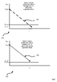
- FIG. 7 shows two exemplary voltage profiles 300 and 308.
- Voltage profile 300 is represented in the form of a graph 304
- voltage profile 308 is represented in the form of a graph 312.
- Voltage profile 300 represents a profile that will cause supervisor circuit 70 to cause device 30 to enter sleep mode.
- Voltage profile 300 represents the drop in voltage of battery 66 from V Start1 when the ambient temperature is about A °C and flash 50 is used at its full setting, drawing about one ampere of power, over a full time period t of about 80 milliseconds.
- voltage profile 308 represents a profile that will NOT cause supervisor circuit 70 to cause device 30 to enter sleep mode.
- Voltage profile 308 represents the drop in voltage of battery 66 from V Start2 when the ambient temperature is about A °C and flash 50 is used at its full setting, drawing about one ampere of power, over a full time period t of about 80 milliseconds.
- profiles 300 and 308 are idealized for purposes of explanation, and that in practice such profiles are not necessarily linear.
- profiles 300 and 308 can be gathered for different V Start voltages of battery 66 and different ambient temperatures A °C.
- An "average" version of profiles (such as profile 300 and 308) can be established by determining profiles for a number of substantially identical copies of device 30, so that variability between devices can be ascertained and considered when establishing profiles. (Such variability can include battery age, battery quality, and/or overall quality of all of the components that comprise device 30, and the manufacturing processes affecting the same. For example, some seemingly identical flash components like flash 50 will consume more power than others.)
- profiles 300 and 308 are reproduced, except that graph 304 includes a pre-function test profile 316, while graph 312 includes a pre-function test profile 320.
- Pre-function test profiles 316 and 320 are examples of the actual effect that step 220 or step 220a can have when performed on device 30.
- step 240 it would be determined that the battery level is below the predetermined threshold and so method 200 would advance from step 240 to step 250.
- step 240 it would be determined that the battery level is NOT below a predetermined threshold and so method 200 would advance from step 240 to step 260.
Landscapes
- Engineering & Computer Science (AREA)
- Multimedia (AREA)
- Signal Processing (AREA)
- Theoretical Computer Science (AREA)
- Physics & Mathematics (AREA)
- General Physics & Mathematics (AREA)
- General Engineering & Computer Science (AREA)
- Secondary Cells (AREA)
- Studio Devices (AREA)
- Charge And Discharge Circuits For Batteries Or The Like (AREA)
- Camera Bodies And Camera Details Or Accessories (AREA)
- Control Of Eletrric Generators (AREA)
- Control Of Electric Motors In General (AREA)
- Ignition Installations For Internal Combustion Engines (AREA)
- Testing Electric Properties And Detecting Electric Faults (AREA)
Claims (14)
- Elektronische Vorrichtung (30), die aufweist:eine Stromversorgung;ein Überwachungsschaltung (70), die mit der Stromversorgung verbunden ist, zum Deaktivieren aller oder eines Teils von Funktionen der elektronischen Vorrichtung, wenn ein erster Leistungspegel von der Stromversorgung unter einen vordefinierten Schwellenwert fällt,eine Funkvorrichtung (62), wobei die Überwachungsschaltung (70) konfiguriert ist, die Funkvorrichtung zu deaktivieren, wenn die Stromversorgung für zumindest fünf Millisekunden unter 3,4 Volt fällt;einen Prozessor (54), der mit der Stromversorgung und der Überwachungsschaltung verbunden ist; wobei der Prozessor konfiguriert ist, über eine Eingabevorrichtung eine Anforderung für eine Durchführung einer Funktion durch die elektronische Vorrichtung zu empfangen;eine Ausgabevorrichtung (42, 50), die mit der Stromversorgung, dem Prozessor und der Überwachungsschaltung verbunden ist, wobei die Ausgabevorrichtung konfiguriert ist, eine Funktion durchzuführen, die Strom von der Stromversorgung benötigt;wobei der Prozessor (54) konfiguriert ist, die Schritte durchzuführen:Durchführen eines Vorfunktionstests; wobei der Vorfunktionstest auf der Funktion basiert und ausgewählt ist, weniger Leistung als die Funktion zu verbrauchen, und weiter ausgewählt ist, damit der erste Leistungspegel nicht unter den vordefinierten Schwellenwert fällt; Bestimmen eines zweiten Leistungspegels der Vorrichtung als eine Folge des Durchführens des Vorfunktionstests; undwenn der zweite Leistungspegel zumindest ein vordefiniertes Kriterium erfüllt, Verhindern, dass die Vorrichtung die Funktion durchführt, oder ansonsten Ermöglichen, dass die Vorrichtung die Funktion durchführt.
- Elektronische Vorrichtung (30) gemäß Anspruch 1, wobei die Ausgabevorrichtung ein Blitz (50) einer Kamera ist.
- Elektronische Vorrichtung (30) gemäß Anspruch 2, wobei der Prozessor (54) konfiguriert ist, den Blitz (50) gemäß der Funktion für eine Zeitdauer von ungefähr achtzig Millisekunden zu aktivieren, und Strom von ungefähr einem Ampere aufnimmt; und wobei der Prozessor (54) konfiguriert ist, den Blitz gemäß dem Vorfunktionstest für eine Zeitdauer von ungefähr zwei Millisekunden zu aktivieren, und Strom von ungefähr einem Ampere aufnimmt.
- Elektronische Vorrichtung (30) gemäß einem der Ansprüche 1 bis 3, wobei, in Verbindung mit dem Verhindern, dass die Vorrichtung die Funktion durchführt, die Vorrichtung konfiguriert ist, ein Ausgabesignal zu erzeugen, das anzeigt, dass es keine ausreichende Leistung gibt, um die Funktion durchzuführen.
- Elektronische Vorrichtung (30) gemäß einem der Ansprüche 1 bis 4, wobei die Vorrichtung eine aufladbare Batterie (66) hat, die in der elektronischen Vorrichtung untergebracht ist, zum Liefern von Leistung.
- Elektronische Vorrichtung (30) gemäß einem der Ansprüche 1 bis 5, wobei der Prozessor (54) konfiguriert ist, den ersten Leistungspegel und den zweiten Leistungspegel zu messen unter Verwendung eines oder mehrerer aus Batteriespannung, Batteriestromstärke, Batterieäquivalenten-Serienwiderstand und Batterietemperatur.
- Elektronische Vorrichtung (30) gemäß einem der Ansprüche 1 bis 6, wobei der Prozessor (54) konfiguriert ist, den Batteriepegel vor und/oder nach einem Durchführen des Vorfunktionstests und/oder während der Durchführung des Vorfunktionstests zu messen.
- Elektronische Vorrichtung (30) gemäß einem der Ansprüche 1 bis 7, wobei der Prozessor (54) konfiguriert ist, den Batteriepegel einmal vor und einmal nach einem Durchführen des Vorfunktionstests zu messen.
- Elektronische Vorrichtung gemäß einem der Ansprüche 1 bis 8, wobei der Prozessor konfiguriert ist, ein zeitlich variierendes Profil von einem oder mehreren Parametern zu erfassen, die einen Batteriepegel anzeigen, während der Durchführung des Vorfunktionstests.
- Elektronische Vorrichtung (30) gemäß einem der Ansprüche 1 bis 9, wobei der Prozessor (54) weiter konfiguriert ist, nach dem Verhindern, dass die elektronische Vorrichtung die Funktion durchführt, der Ausgabevorrichtung (42, 50) zu ermöglichen, eine alternative Funktion durchzuführen, die weniger Leistung als die Funktion verbraucht.
- Elektronische Vorrichtung gemäß Anspruch 10, wobei die Funktion ein Kamerablitz ist, der mit voller Leistung verwendet wird, und die alternative Funktion der Kamerablitz ist, der bei weniger als der vollen Leistung verwendet wird.
- Elektronische Vorrichtung gemäß Anspruch 11, wobei die alternative Funktion konfiguriert ist, einen dritten Leistungspegel zu verbrauchen, der gewählt ist derart, dass der erste Leistungspegel nicht unter den vordefinierten Schwellenwert fällt.
- Elektronische Vorrichtung gemäß Anspruch 1, wobei die Überwachungsschaltung (70) konfiguriert ist, die elektronische Vorrichtung in einen Schlafmodus zu bringen, wenn die Stromversorgung für zumindest drei Millisekunden unter 3,1 Volt fällt.
- Elektronische Vorrichtung gemäß einem der Ansprüche 1 bis 8, wobei der Prozessor konfiguriert ist, einen Durchschnitt einer Vielzahl von zeitlich variierenden Profilen von einem oder mehreren Parametern zu verwenden, die einen Batteriepegel anzeigen, während der Durchführung des Vorfunktionstests.
Priority Applications (3)
| Application Number | Priority Date | Filing Date | Title |
|---|---|---|---|
| DE602006012231T DE602006012231D1 (de) | 2006-08-10 | 2006-08-10 | Vorrichtung zur Leistungssteuerung in einer elektronischen Vorrichtung |
| AT09179688T ATE498155T1 (de) | 2006-08-10 | 2006-08-10 | Verfahren und vorrichtung zur leistungssteuerung in einer elektronischen vorrichtung |
| EP09179688A EP2177970B1 (de) | 2006-08-10 | 2006-08-10 | Verfahren und Vorrichtung zur Leistungssteuerung in einer elektronischen Vorrichtung |
Applications Claiming Priority (1)
| Application Number | Priority Date | Filing Date | Title |
|---|---|---|---|
| EP06118750A EP1887450B1 (de) | 2006-08-10 | 2006-08-10 | Verfahren und Vorrichtung zur Leistungssteuerung in einer elektronischen Vorrichtung |
Related Parent Applications (1)
| Application Number | Title | Priority Date | Filing Date |
|---|---|---|---|
| EP06118750A Division EP1887450B1 (de) | 2006-08-10 | 2006-08-10 | Verfahren und Vorrichtung zur Leistungssteuerung in einer elektronischen Vorrichtung |
Publications (2)
| Publication Number | Publication Date |
|---|---|
| EP2003533A1 EP2003533A1 (de) | 2008-12-17 |
| EP2003533B1 true EP2003533B1 (de) | 2010-02-10 |
Family
ID=37667626
Family Applications (3)
| Application Number | Title | Priority Date | Filing Date |
|---|---|---|---|
| EP09179688A Active EP2177970B1 (de) | 2006-08-10 | 2006-08-10 | Verfahren und Vorrichtung zur Leistungssteuerung in einer elektronischen Vorrichtung |
| EP06118750A Active EP1887450B1 (de) | 2006-08-10 | 2006-08-10 | Verfahren und Vorrichtung zur Leistungssteuerung in einer elektronischen Vorrichtung |
| EP08165796A Active EP2003533B1 (de) | 2006-08-10 | 2006-08-10 | Vorrichtung zur Leistungssteuerung in einer elektronischen Vorrichtung |
Family Applications Before (2)
| Application Number | Title | Priority Date | Filing Date |
|---|---|---|---|
| EP09179688A Active EP2177970B1 (de) | 2006-08-10 | 2006-08-10 | Verfahren und Vorrichtung zur Leistungssteuerung in einer elektronischen Vorrichtung |
| EP06118750A Active EP1887450B1 (de) | 2006-08-10 | 2006-08-10 | Verfahren und Vorrichtung zur Leistungssteuerung in einer elektronischen Vorrichtung |
Country Status (6)
| Country | Link |
|---|---|
| EP (3) | EP2177970B1 (de) |
| CN (2) | CN101183275B (de) |
| AT (3) | ATE498155T1 (de) |
| CA (2) | CA2596748C (de) |
| DE (3) | DE602006020085D1 (de) |
| SG (2) | SG139730A1 (de) |
Families Citing this family (10)
| Publication number | Priority date | Publication date | Assignee | Title |
|---|---|---|---|---|
| US8964113B2 (en) | 2012-10-01 | 2015-02-24 | Axis Ab | Method and arrangement in a monitoring camera |
| EP2713238B1 (de) * | 2012-10-01 | 2014-11-26 | Axis AB | Leistungsverwaltung in einer Überwachungskamera |
| CN103501384A (zh) * | 2013-09-17 | 2014-01-08 | 广东明创软件科技有限公司 | 手机拍照调节闪光灯电流的方法及手机 |
| US9204044B2 (en) * | 2013-10-02 | 2015-12-01 | Nokia Technologies Oy | Method and apparatus for optimization during camera flash pulses |
| US9426748B2 (en) | 2014-07-11 | 2016-08-23 | Qualcomm Incorporated | Dynamic sleep mode based upon battery charge |
| CN104822018A (zh) * | 2015-03-26 | 2015-08-05 | 深圳市金立通信设备有限公司 | 一种拍照装置的闪光灯控制方法 |
| CN104778040A (zh) * | 2015-03-26 | 2015-07-15 | 深圳市金立通信设备有限公司 | 一种拍照装置 |
| US9824203B2 (en) * | 2015-04-15 | 2017-11-21 | Motorola Mobility Llc | Utilizing a radio frequency identification tag to assess the battery level of a peripheral device |
| CN105847527B (zh) * | 2015-06-25 | 2019-09-27 | 维沃移动通信有限公司 | 一种防止移动终端自动关机的方法和移动终端 |
| JP2019036925A (ja) * | 2017-08-21 | 2019-03-07 | ソニーセミコンダクタソリューションズ株式会社 | 撮像装置、および、撮像装置の制御方法 |
Family Cites Families (10)
| Publication number | Priority date | Publication date | Assignee | Title |
|---|---|---|---|---|
| US4290677A (en) * | 1980-09-08 | 1981-09-22 | Eastman Kodak Company | Apparatus for checking the operational status of an electronic strobe unit's battery under load conditions |
| JPH0667766A (ja) * | 1992-08-21 | 1994-03-11 | Fujitsu Ltd | 携帯端末装置 |
| US5461288A (en) * | 1993-01-27 | 1995-10-24 | Chaves; Neal | Power management device for large electronic flash units |
| KR970006278B1 (ko) * | 1993-04-14 | 1997-04-25 | 삼성항공산업 주식회사 | 충전량에 따라 자동 발광하는 카메라 및 그 제어방법 |
| US5963255A (en) * | 1996-04-16 | 1999-10-05 | Apple Computer, Inc. | System and method for managing utilization of a battery |
| JP4288553B2 (ja) * | 2000-07-25 | 2009-07-01 | 富士フイルム株式会社 | カメラのストロボ装置 |
| CN1229708C (zh) * | 2000-11-28 | 2005-11-30 | Lg电子株式会社 | 一种基于电池剩余容量控制盘写入操作的方法 |
| JP2003174587A (ja) * | 2001-12-07 | 2003-06-20 | Seiko Precision Inc | 撮像装置および携帯電子機器 |
| KR100504805B1 (ko) * | 2002-10-24 | 2005-07-29 | 엘지전자 주식회사 | 화상통신용 휴대 단말기의 동영상 처리 장치 |
| JP2004260615A (ja) * | 2003-02-26 | 2004-09-16 | Canon Inc | 撮像装置 |
-
2006
- 2006-08-10 DE DE602006020085T patent/DE602006020085D1/de active Active
- 2006-08-10 AT AT09179688T patent/ATE498155T1/de not_active IP Right Cessation
- 2006-08-10 AT AT08165796T patent/ATE457485T1/de not_active IP Right Cessation
- 2006-08-10 DE DE602006012231T patent/DE602006012231D1/de active Active
- 2006-08-10 AT AT06118750T patent/ATE417311T1/de not_active IP Right Cessation
- 2006-08-10 EP EP09179688A patent/EP2177970B1/de active Active
- 2006-08-10 EP EP06118750A patent/EP1887450B1/de active Active
- 2006-08-10 DE DE602006004208T patent/DE602006004208D1/de active Active
- 2006-08-10 EP EP08165796A patent/EP2003533B1/de active Active
-
2007
- 2007-08-08 CN CN2007103051274A patent/CN101183275B/zh active Active
- 2007-08-08 CN CN201110153833.8A patent/CN102226864B/zh active Active
- 2007-08-09 CA CA2596748A patent/CA2596748C/en active Active
- 2007-08-09 CA CA2710704A patent/CA2710704C/en active Active
- 2007-08-10 SG SG200705864-7A patent/SG139730A1/en unknown
- 2007-08-10 SG SG200907477-4A patent/SG157382A1/en unknown
Also Published As
| Publication number | Publication date |
|---|---|
| DE602006012231D1 (de) | 2010-03-25 |
| ATE417311T1 (de) | 2008-12-15 |
| CN101183275B (zh) | 2011-07-27 |
| EP1887450A1 (de) | 2008-02-13 |
| EP2177970B1 (de) | 2011-02-09 |
| CN101183275A (zh) | 2008-05-21 |
| ATE457485T1 (de) | 2010-02-15 |
| DE602006020085D1 (de) | 2011-03-24 |
| CA2710704A1 (en) | 2008-02-10 |
| CN102226864A (zh) | 2011-10-26 |
| CA2710704C (en) | 2015-07-21 |
| DE602006004208D1 (de) | 2009-01-22 |
| CA2596748C (en) | 2010-11-16 |
| SG139730A1 (en) | 2008-02-29 |
| CN102226864B (zh) | 2014-05-07 |
| EP1887450B1 (de) | 2008-12-10 |
| SG157382A1 (en) | 2009-12-29 |
| ATE498155T1 (de) | 2011-02-15 |
| EP2003533A1 (de) | 2008-12-17 |
| CA2596748A1 (en) | 2008-02-10 |
| EP2177970A1 (de) | 2010-04-21 |
Similar Documents
| Publication | Publication Date | Title |
|---|---|---|
| US7970272B2 (en) | Method and apparatus for power management in an electronic device | |
| CA2596748C (en) | Method and apparatus for power management in an electronic device | |
| JP5119136B2 (ja) | 電子装置及びその制御方法 | |
| US20080074535A1 (en) | Imaging apparatus | |
| EP2017943A2 (de) | Batteriegetriebene Vorrichtung mit Stromsparmodus | |
| JP2008193784A (ja) | 電子機器、その制御方法、及びプログラム | |
| US20150113301A1 (en) | Charging method and mobile electronic device | |
| US10121350B2 (en) | Information device | |
| JP4829973B2 (ja) | 補聴器および補聴器におけるバッテリ・アラームの鳴動方法 | |
| JP2016208648A (ja) | 電子機器、制御方法およびプログラム | |
| US10652463B2 (en) | Imaging device having a charge controller for regulating battery charging during interval shooting | |
| US6351611B1 (en) | Battery check system for use in cameras | |
| JP2018026780A (ja) | 情報装置 | |
| TWI220364B (en) | Digital camera of automatically monitoring environmental change | |
| JP2000324239A (ja) | 携帯電話機 | |
| JP2010124064A (ja) | 電子装置及びその制御方法 | |
| EP1925976B1 (de) | Bildaufzeichnungsvorrichtung mit variabler Taktfrequenz je nach Stromversorgung | |
| KR100698314B1 (ko) | 촬영 기능을 갖는 이동통신단말기 및 이를 이용한 방법 | |
| JP2005018033A (ja) | カメラ制御装置、電子スチルカメラ | |
| JP2007206126A (ja) | 閃光装置、閃光装置付きカメラ、閃光制御方法及びプログラム | |
| JP2018152976A (ja) | 撮像装置 | |
| JP2018074221A (ja) | 撮像装置 | |
| JP2005006135A (ja) | 画像撮影装置及び該装置の省電力方法 |
Legal Events
| Date | Code | Title | Description |
|---|---|---|---|
| PUAI | Public reference made under article 153(3) epc to a published international application that has entered the european phase |
Free format text: ORIGINAL CODE: 0009012 |
|
| 17P | Request for examination filed |
Effective date: 20081002 |
|
| AC | Divisional application: reference to earlier application |
Ref document number: 1887450 Country of ref document: EP Kind code of ref document: P |
|
| AK | Designated contracting states |
Kind code of ref document: A1 Designated state(s): AT BE BG CH CY CZ DE DK EE ES FI FR GB GR HU IE IS IT LI LT LU LV MC NL PL PT RO SE SI SK TR |
|
| AX | Request for extension of the european patent |
Extension state: AL BA HR MK RS |
|
| GRAP | Despatch of communication of intention to grant a patent |
Free format text: ORIGINAL CODE: EPIDOSNIGR1 |
|
| AKX | Designation fees paid |
Designated state(s): AT BE BG CH CY CZ DE DK EE ES FI FR GB GR HU IE IS IT LI LT LU LV MC NL PL PT RO SE SI SK TR |
|
| AXX | Extension fees paid |
Extension state: BA Payment date: 20081002 Extension state: RS Payment date: 20081002 Extension state: MK Payment date: 20081002 Extension state: HR Payment date: 20081002 Extension state: AL Payment date: 20081002 |
|
| RTI1 | Title (correction) |
Free format text: APPARATUS FOR POWER MANAGEMENT IN AN ELECTRONIC DEVICE |
|
| GRAS | Grant fee paid |
Free format text: ORIGINAL CODE: EPIDOSNIGR3 |
|
| GRAA | (expected) grant |
Free format text: ORIGINAL CODE: 0009210 |
|
| AC | Divisional application: reference to earlier application |
Ref document number: 1887450 Country of ref document: EP Kind code of ref document: P |
|
| AK | Designated contracting states |
Kind code of ref document: B1 Designated state(s): AT BE BG CH CY CZ DE DK EE ES FI FR GB GR HU IE IS IT LI LT LU LV MC NL PL PT RO SE SI SK TR |
|
| AX | Request for extension of the european patent |
Extension state: AL BA HR MK RS |
|
| REG | Reference to a national code |
Ref country code: GB Ref legal event code: FG4D |
|
| REG | Reference to a national code |
Ref country code: CH Ref legal event code: EP |
|
| REG | Reference to a national code |
Ref country code: IE Ref legal event code: FG4D |
|
| REF | Corresponds to: |
Ref document number: 602006012231 Country of ref document: DE Date of ref document: 20100325 Kind code of ref document: P |
|
| REG | Reference to a national code |
Ref country code: NL Ref legal event code: VDEP Effective date: 20100210 |
|
| LTIE | Lt: invalidation of european patent or patent extension |
Effective date: 20100210 |
|
| PG25 | Lapsed in a contracting state [announced via postgrant information from national office to epo] |
Ref country code: PT Free format text: LAPSE BECAUSE OF FAILURE TO SUBMIT A TRANSLATION OF THE DESCRIPTION OR TO PAY THE FEE WITHIN THE PRESCRIBED TIME-LIMIT Effective date: 20100611 Ref country code: IS Free format text: LAPSE BECAUSE OF FAILURE TO SUBMIT A TRANSLATION OF THE DESCRIPTION OR TO PAY THE FEE WITHIN THE PRESCRIBED TIME-LIMIT Effective date: 20100610 Ref country code: ES Free format text: LAPSE BECAUSE OF FAILURE TO SUBMIT A TRANSLATION OF THE DESCRIPTION OR TO PAY THE FEE WITHIN THE PRESCRIBED TIME-LIMIT Effective date: 20100521 Ref country code: LT Free format text: LAPSE BECAUSE OF FAILURE TO SUBMIT A TRANSLATION OF THE DESCRIPTION OR TO PAY THE FEE WITHIN THE PRESCRIBED TIME-LIMIT Effective date: 20100210 |
|
| PG25 | Lapsed in a contracting state [announced via postgrant information from national office to epo] |
Ref country code: PL Free format text: LAPSE BECAUSE OF FAILURE TO SUBMIT A TRANSLATION OF THE DESCRIPTION OR TO PAY THE FEE WITHIN THE PRESCRIBED TIME-LIMIT Effective date: 20100210 Ref country code: SI Free format text: LAPSE BECAUSE OF FAILURE TO SUBMIT A TRANSLATION OF THE DESCRIPTION OR TO PAY THE FEE WITHIN THE PRESCRIBED TIME-LIMIT Effective date: 20100210 Ref country code: AT Free format text: LAPSE BECAUSE OF FAILURE TO SUBMIT A TRANSLATION OF THE DESCRIPTION OR TO PAY THE FEE WITHIN THE PRESCRIBED TIME-LIMIT Effective date: 20100210 Ref country code: FI Free format text: LAPSE BECAUSE OF FAILURE TO SUBMIT A TRANSLATION OF THE DESCRIPTION OR TO PAY THE FEE WITHIN THE PRESCRIBED TIME-LIMIT Effective date: 20100210 Ref country code: LV Free format text: LAPSE BECAUSE OF FAILURE TO SUBMIT A TRANSLATION OF THE DESCRIPTION OR TO PAY THE FEE WITHIN THE PRESCRIBED TIME-LIMIT Effective date: 20100210 |
|
| PG25 | Lapsed in a contracting state [announced via postgrant information from national office to epo] |
Ref country code: BE Free format text: LAPSE BECAUSE OF FAILURE TO SUBMIT A TRANSLATION OF THE DESCRIPTION OR TO PAY THE FEE WITHIN THE PRESCRIBED TIME-LIMIT Effective date: 20100210 Ref country code: CY Free format text: LAPSE BECAUSE OF FAILURE TO SUBMIT A TRANSLATION OF THE DESCRIPTION OR TO PAY THE FEE WITHIN THE PRESCRIBED TIME-LIMIT Effective date: 20100210 Ref country code: EE Free format text: LAPSE BECAUSE OF FAILURE TO SUBMIT A TRANSLATION OF THE DESCRIPTION OR TO PAY THE FEE WITHIN THE PRESCRIBED TIME-LIMIT Effective date: 20100210 Ref country code: GR Free format text: LAPSE BECAUSE OF FAILURE TO SUBMIT A TRANSLATION OF THE DESCRIPTION OR TO PAY THE FEE WITHIN THE PRESCRIBED TIME-LIMIT Effective date: 20100511 Ref country code: NL Free format text: LAPSE BECAUSE OF FAILURE TO SUBMIT A TRANSLATION OF THE DESCRIPTION OR TO PAY THE FEE WITHIN THE PRESCRIBED TIME-LIMIT Effective date: 20100210 Ref country code: RO Free format text: LAPSE BECAUSE OF FAILURE TO SUBMIT A TRANSLATION OF THE DESCRIPTION OR TO PAY THE FEE WITHIN THE PRESCRIBED TIME-LIMIT Effective date: 20100210 Ref country code: SE Free format text: LAPSE BECAUSE OF FAILURE TO SUBMIT A TRANSLATION OF THE DESCRIPTION OR TO PAY THE FEE WITHIN THE PRESCRIBED TIME-LIMIT Effective date: 20100210 |
|
| PG25 | Lapsed in a contracting state [announced via postgrant information from national office to epo] |
Ref country code: SK Free format text: LAPSE BECAUSE OF FAILURE TO SUBMIT A TRANSLATION OF THE DESCRIPTION OR TO PAY THE FEE WITHIN THE PRESCRIBED TIME-LIMIT Effective date: 20100210 Ref country code: BG Free format text: LAPSE BECAUSE OF FAILURE TO SUBMIT A TRANSLATION OF THE DESCRIPTION OR TO PAY THE FEE WITHIN THE PRESCRIBED TIME-LIMIT Effective date: 20100510 Ref country code: CZ Free format text: LAPSE BECAUSE OF FAILURE TO SUBMIT A TRANSLATION OF THE DESCRIPTION OR TO PAY THE FEE WITHIN THE PRESCRIBED TIME-LIMIT Effective date: 20100210 |
|
| PLBE | No opposition filed within time limit |
Free format text: ORIGINAL CODE: 0009261 |
|
| STAA | Information on the status of an ep patent application or granted ep patent |
Free format text: STATUS: NO OPPOSITION FILED WITHIN TIME LIMIT |
|
| 26N | No opposition filed |
Effective date: 20101111 |
|
| PG25 | Lapsed in a contracting state [announced via postgrant information from national office to epo] |
Ref country code: DK Free format text: LAPSE BECAUSE OF FAILURE TO SUBMIT A TRANSLATION OF THE DESCRIPTION OR TO PAY THE FEE WITHIN THE PRESCRIBED TIME-LIMIT Effective date: 20100210 |
|
| PG25 | Lapsed in a contracting state [announced via postgrant information from national office to epo] |
Ref country code: MC Free format text: LAPSE BECAUSE OF NON-PAYMENT OF DUE FEES Effective date: 20100831 Ref country code: IT Free format text: LAPSE BECAUSE OF FAILURE TO SUBMIT A TRANSLATION OF THE DESCRIPTION OR TO PAY THE FEE WITHIN THE PRESCRIBED TIME-LIMIT Effective date: 20100210 |
|
| REG | Reference to a national code |
Ref country code: CH Ref legal event code: PL |
|
| PG25 | Lapsed in a contracting state [announced via postgrant information from national office to epo] |
Ref country code: CH Free format text: LAPSE BECAUSE OF NON-PAYMENT OF DUE FEES Effective date: 20100831 Ref country code: LI Free format text: LAPSE BECAUSE OF NON-PAYMENT OF DUE FEES Effective date: 20100831 |
|
| PG25 | Lapsed in a contracting state [announced via postgrant information from national office to epo] |
Ref country code: IE Free format text: LAPSE BECAUSE OF NON-PAYMENT OF DUE FEES Effective date: 20100810 |
|
| PG25 | Lapsed in a contracting state [announced via postgrant information from national office to epo] |
Ref country code: HU Free format text: LAPSE BECAUSE OF FAILURE TO SUBMIT A TRANSLATION OF THE DESCRIPTION OR TO PAY THE FEE WITHIN THE PRESCRIBED TIME-LIMIT Effective date: 20100811 Ref country code: LU Free format text: LAPSE BECAUSE OF NON-PAYMENT OF DUE FEES Effective date: 20100810 |
|
| PG25 | Lapsed in a contracting state [announced via postgrant information from national office to epo] |
Ref country code: TR Free format text: LAPSE BECAUSE OF FAILURE TO SUBMIT A TRANSLATION OF THE DESCRIPTION OR TO PAY THE FEE WITHIN THE PRESCRIBED TIME-LIMIT Effective date: 20100210 |
|
| REG | Reference to a national code |
Ref country code: DE Ref legal event code: R082 Ref document number: 602006012231 Country of ref document: DE Representative=s name: MERH-IP MATIAS ERNY REICHL HOFFMANN, DE |
|
| REG | Reference to a national code |
Ref country code: DE Ref legal event code: R082 Ref document number: 602006012231 Country of ref document: DE Representative=s name: MERH-IP MATIAS ERNY REICHL HOFFMANN, DE Effective date: 20140925 Ref country code: DE Ref legal event code: R081 Ref document number: 602006012231 Country of ref document: DE Owner name: BLACKBERRY LIMITED, WATERLOO, CA Free format text: FORMER OWNER: RESEARCH IN MOTION LTD., WATERLOO, ONTARIO, CA Effective date: 20140925 Ref country code: DE Ref legal event code: R082 Ref document number: 602006012231 Country of ref document: DE Representative=s name: MERH-IP MATIAS ERNY REICHL HOFFMANN PATENTANWA, DE Effective date: 20140925 |
|
| REG | Reference to a national code |
Ref country code: FR Ref legal event code: PLFP Year of fee payment: 11 |
|
| REG | Reference to a national code |
Ref country code: FR Ref legal event code: PLFP Year of fee payment: 12 |
|
| REG | Reference to a national code |
Ref country code: FR Ref legal event code: PLFP Year of fee payment: 13 |
|
| REG | Reference to a national code |
Ref country code: DE Ref legal event code: R082 Ref document number: 602006012231 Country of ref document: DE Ref country code: DE Ref legal event code: R081 Ref document number: 602006012231 Country of ref document: DE Owner name: MALIKIE INNOVATIONS LTD., IE Free format text: FORMER OWNER: BLACKBERRY LIMITED, WATERLOO, ONTARIO, CA |
|
| PGFP | Annual fee paid to national office [announced via postgrant information from national office to epo] |
Ref country code: DE Payment date: 20250827 Year of fee payment: 20 |
|
| PGFP | Annual fee paid to national office [announced via postgrant information from national office to epo] |
Ref country code: GB Payment date: 20250826 Year of fee payment: 20 |
|
| PGFP | Annual fee paid to national office [announced via postgrant information from national office to epo] |
Ref country code: FR Payment date: 20250825 Year of fee payment: 20 |