EP2003759A1 - Procédé destiné à la détection de réseau pour île - Google Patents
Procédé destiné à la détection de réseau pour île Download PDFInfo
- Publication number
- EP2003759A1 EP2003759A1 EP20070013347 EP07013347A EP2003759A1 EP 2003759 A1 EP2003759 A1 EP 2003759A1 EP 20070013347 EP20070013347 EP 20070013347 EP 07013347 A EP07013347 A EP 07013347A EP 2003759 A1 EP2003759 A1 EP 2003759A1
- Authority
- EP
- European Patent Office
- Prior art keywords
- frequency
- voltage
- test
- inverter
- signal
- Prior art date
- Legal status (The legal status is an assumption and is not a legal conclusion. Google has not performed a legal analysis and makes no representation as to the accuracy of the status listed.)
- Granted
Links
Images


Classifications
-
- H—ELECTRICITY
- H02—GENERATION; CONVERSION OR DISTRIBUTION OF ELECTRIC POWER
- H02J—ELECTRIC POWER NETWORKS; CIRCUIT ARRANGEMENTS OR SYSTEMS FOR SUPPLYING OR DISTRIBUTING ELECTRIC POWER; SYSTEMS FOR STORING ELECTRIC ENERGY
- H02J3/00—Circuit arrangements for AC mains or AC distribution networks
- H02J3/38—Arrangements for feeding a single network from two or more generators or sources in parallel; Arrangements for feeding already energised networks from additional generators or sources in parallel
- H02J3/388—Arrangements for the handling of islanding, e.g. for disconnection or for avoiding the disconnection of power
Definitions
- the invention relates to a method for island grid detection for a converter leading a converter voltage, which is connected in parallel to a power grid with a grid frequency and electrical loads and which is decoupled by a throttle from the power grid.
- a self-generation facility must detect if the public grid fails and then stop operating. It may not continue to feed into the grid because it may cause personal injury during maintenance work in the public grid if a section of the grid has been disconnected, but the in-house generating system continues to operate in this section.
- Known network monitoring methods are divided into passive and active methods. Passive methods evaluate only the measured values of mains voltage (single or three-phase) and mains frequency. Active methods influence the network by means of current or voltage distortions in such a way that it is possible to conclude from the response to the network parameters or to the network impedance. By a current distortion one receives a voltage response, by a voltage distortion a current response.
- test current has at least two frequencies other than the mains frequency.
- the impedance of the network is determined at these test frequencies. This in turn implies the impedance at mains frequency. In the case of strong impedance changes, it is then assumed that islanding is present.
- the method is computationally time consuming because the computations of the impedances are performed using complex algorithms (e.g., FFT).
- complex algorithms e.g., FFT
- the invention has for its object to provide a method that reliably allows island detection, with additional energy consumption for the provision of an uninterruptible power supply should be minimal and unpleasant side effects, such as additional component load or noise to be avoided.
- This object is achieved in that the converter voltage is superimposed on a test signal having a test frequency whose frequency is smaller than the mains frequency, the amplitude of the test signal on the one hand much smaller than the rated voltage amplitude of the mains voltage, but on the other hand is just so big that reactive power changes due to the test signal can be detected, from which a reactive power component is determined, which oscillates at the test frequency, wherein this proportion must not fall below a predetermined minimum, so that off-grid operation can be safely excluded.
- the invention is based on the finding that during operation the reactive power flow changes with the test frequency when the public grid is stable. If the public grid fails, the reactive power flow experiences little change due to the test signal.
- test frequency which is smaller than the mains frequency, wherein its amplitude is small compared to the mains voltage, wherein the network-side reactive power component which oscillates at the test frequency, but can still be determined.
- This proportion must not fall below a specified minimum, so that off-grid operation can be safely excluded.
- the inventive method has the advantage that the additional energy consumption is minimal. There is no or only a small additional component load. The process also does not cause any noise; existing algorithms for reactive power determination can be used. additional energy consumption for providing an uninterruptible power supply is minimal; Displacements of the zero crossing, e.g. caused by ripple control signals, do not lead to unintentional island network detections. Also, it is not necessary to analyze several frequencies computationally. As a result, the computational effort is minimal.
- the voltage amplitude of the test signal is less than 2% of the rated voltage amplitude of the mains voltage.
- the frequency of the test frequency is considerably smaller than the mains frequency, in particular if the frequency of the test signal is 0.5 to 5 Hz. This frequency can be filtered out well, because it is far away from the mains frequency.
- a further advantageous embodiment of the invention is characterized in that the proportion of oscillating with the test frequency Net blind power is filtered out using at least one so-called generalized integrator.
- Such integrators work reliably and are for example from the DE 199 49 997 A1 known.
- a suitable FFT or a normal Fourier transformation can be used.
- other suitable methods for determining a characteristic variable from a time-periodic signal can also be used.
- the method according to the invention is applicable to a three-phase system.
- a failed network is preferably separated by means of a transfer contactor.
- the inverter is designed as a battery inverter, the battery is used as an electrical energy storage in case of power failure or to save excess energy of a photovoltaic generator.
- the inverter can also be used for a variable speed combustion engine, z. B. for a wind generator, a hydropower plant or a photovoltaic system, be executed. Again, it is important to disconnect these generators from the grid, if this has failed.
- a good concept is when at least one additional second inverter connected to a generator, in particular a photovoltaic generator, is connected in parallel with the inverter.
- electrical loads can be fed either from the public grid, from the photovoltaic generator and / or from the battery.
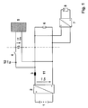
- Fig. 1 shows a representation of a circuit arrangement with a battery inverter 2.
- the circuit arrangement is a self-generating system for electrical energy. It includes, in addition to the battery inverter 2, to which a rechargeable battery 1 is connected, also a solar generator or photovoltaic generator 8 with a second inverter 7, which is connected in parallel to the battery inverter.
- the battery inverter 2 is connected in parallel to a power supply network 5 with a throttle 3, wherein a transfer protection 4 is arranged therebetween.
- a wind turbine with a PM generator, a variable-speed combustion engine, a fuel cell and the like can also be used. These are increasingly used for energy generation.
- a self-generation facility must detect if the public grid fails and then stop operating. It may not continue to feed into the grid because it may cause personal injury during maintenance work in the public grid if a section of the grid has been disconnected, but the in-house generating system continues to operate in this section.
- a self-generation plant according to Fig. 1 is present, the operator would like to continue to supply a consumer 6, if the public power grid fails.
- the self-generating system must be supplemented by the battery-powered additional inverter 2 or battery inverter 2.
- a method for island detection is used for the power converter voltage leading inverter 2, which operates in parallel to the power grid 5 with a mains frequency of 50 or 60 Hz and is connected to the electrical loads 8.
- the inverter 2 is decoupled from the power supply network 5 by the throttle 3.
- the converter voltage is superimposed on a test signal with a test frequency whose frequency is smaller than the mains frequency, the amplitude of the test signal on the one hand much smaller than the nominal voltage amplitude of the mains voltage, but on the other hand just enough so that reactive power changes due to the test signal can be seen , A reactive power component is determined and below a defined value the inverter is disconnected from the grid.
- the battery inverter 2 is in the power failure of the network 5, the supply of the consumer even if the self-generating system at the moment can not provide energy because, for example, cloudy weather with low solar radiation prevails.
- This battery inverter 2 is equipped with the transfer contactor with which the connection of the own generating plant to the public supply network or the network 5 can be interrupted.
- the self-generating system thus consists of the solar inverter 7, the photovoltaic generator 8 and the battery inverter. 2
- the battery 1 is connected to the power supply network 5 via the battery inverter and the decoupling choke 3, as well as via the transfer contactor 4.
- the consumers 6 are supplied by the network 5 or, if the transfer contactor 4 is opened, by the battery inverter 2.
- the solar generator 8 can help via the solar inverter 7 to provide the consumers 6. If more solar energy is generated than the consumer 6 requires, the battery can be charged via the battery inverter 2 or energy can be fed into the network 5.
- the inverter 2 is therefore preferably designed as a bidirectional inverter.
- the converter voltage 11, the mains current 12 and the mains voltage 13 are measured and supplied in digitized form to a suitable digital computer, not shown, in particular a microprocessor.
- the power converter voltage 11 is now a test voltage with very small amplitude, in particular about 1% of the mains voltage or less and a test frequency much smaller the mains frequency of 50Hz or 60Hz superimposed.
- the reactive power ie the power frequency reactive power on the network side, is preferably determined for other control tasks. Therefore, the determination of the reactive power represents no additional effort.
- the portion of the reactive power, which oscillates with the test frequency is filtered out by means of a so-called generalized integrator. Such generalized integrators are used in the DE 199 49 997 A1 detailed.
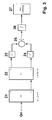
- Fig. 2 such a generalized integrator is illustrated.
- the integrator comprises two subtractors 31 and 32, two amplifiers 33 and 35 and two integrators 34 and 36.
- the amplifiers 33, 35 multiply the respective input signal by an angular frequency to which the generalized integrator is tuned.
- the angular frequency is the test frequency multiplied by 2 x Pi (Hz).
- the input of the circuit shown is the line-side power frequency reactive power.
- the output y one obtains the reactive power component, which oscillates at the test frequency.
- the output x is the reactive power component shifted by 90 ° with respect to the output y, which oscillates at the test frequency.
- Fig. 3 a block diagram for detecting islanding is shown.
- the island network detection can be done by an analog circuit or by a microprocessor program. Therefore, presents Fig. 3 the complete algorithm necessary to detect islanding.
- the network-side power frequency reactive power serves as an input to the generalized integrator 21. Its output y serves as an input to the generalized integrator 22, this then generates the output signals x and y, by 90 ° to each other are shifted. These output signals are then squared in squaring members 23 and 24 and the outputs of the squaring members added in an adder 25; its output is radiated in a radier 26 and finally fed to an evaluation unit 27.
- the evaluation unit 27 and the other members can be realized by a program of the microprocessor, so only by software.
- the output of the Radizierers 26 is a Gleichster.
- the evaluation 27 monitors this equal size. If the DC size falls below a predefined threshold, an island network is formed because the reactive power on the network side does not oscillate or only very slightly with the test frequency.
- Fig. 4 shows a voltage diagram. This serves to illustrate the following mathematical relationship.
- Q Q n i n ⁇ u n
- U s is a converter voltage and U n is a mains voltage.
- U n is a mains voltage.
- a plurality of battery inverters 2 can be connected in parallel. Furthermore, it is advantageous for the inverters to be voltage-controlled, with each inverter 2 having a decoupling choke 3.
- the mains voltage, the grid frequency, the inverter active power and the inverter reactive power are measured.
- the instantaneous mains voltage serves as the basis for calculating the required reactive power setpoint.
- the reactive power is then set by a controller of the battery inverter according to this setpoint.
- the rule is that with decreasing voltage, the reactive power is increased.
- the current network frequency serves as the basis for calculating the required active power setpoint.
- the active power is then set by the controller of the battery inverter 2 according to this setpoint. It is true that with decreasing frequency, the active power is increased.
- a reactive power measurement in the inverter 2 already present in this constellation is preferably made usable in the method according to the invention for off-grid detection.
- the amplitude of the converter voltage is superimposed with a sinusoidal size, wherein the frequency of the superimposed voltage (test frequency) is much smaller than the mains frequency (about 1 to 2 Hz) and the voltage amplitude of the superimposed voltage is just large enough in that the response to this voltage change can be detected with sufficient accuracy (approximately 1% of the nominal voltage amplitude or less).
- the reactive power flow is measured on the network side. When the public grid is stable, this reactive power flow changes with the test frequency. Falls the public supply network off, the reactive power flow then no longer varies or varies significantly less with the test frequency. This change is registered and the loss of the public network is now registered based on the change in reactive power flow. The transfer contactor 4 must then be opened.
- the invention is not limited to this example, so the filtering of the reactive power with respect to the proportion that oscillates at the test frequency, can be done with other algorithms.
- the method can also be used in three-phase systems. Each phase can be considered independently of the other phases.
- the test signals do not need to be synchronized.
- a voltage can be modulated in such a way that the voltage signal in the three phases is shifted by 120 ° relative to the mains frequency. This results in a space vector signal of this three-phase system, to which a voltage at the test frequency is impressed.
- the determination of the reactive power, which oscillates with the test frequency, can then take place from the grid current converted into the space vector model and the grid voltage converted into the room vector model.
- test signals of the individual power converters are then synchronized via a suitable data connection.
- test signals of the individual power converters connected in parallel to the network vary slightly in frequency and can therefore be considered independently.
- the filtering of the reactive power that oscillates at the test frequency can be done using the Görzelalgorithmus, or a suitable FFT or a normal Fourier transform, if a generalized integrator should not be applied.
Landscapes
- Engineering & Computer Science (AREA)
- Power Engineering (AREA)
- Supply And Distribution Of Alternating Current (AREA)
- Inverter Devices (AREA)
Priority Applications (2)
| Application Number | Priority Date | Filing Date | Title |
|---|---|---|---|
| EP07013347.5A EP2003759B1 (fr) | 2007-06-14 | 2007-07-07 | Procédé destiné à la détection d'un réseau îloté |
| US12/157,281 US8035369B2 (en) | 2007-06-14 | 2008-06-09 | Method for detecting an isolated network |
Applications Claiming Priority (2)
| Application Number | Priority Date | Filing Date | Title |
|---|---|---|---|
| EP07011655 | 2007-06-14 | ||
| EP07013347.5A EP2003759B1 (fr) | 2007-06-14 | 2007-07-07 | Procédé destiné à la détection d'un réseau îloté |
Publications (2)
| Publication Number | Publication Date |
|---|---|
| EP2003759A1 true EP2003759A1 (fr) | 2008-12-17 |
| EP2003759B1 EP2003759B1 (fr) | 2020-03-04 |
Family
ID=39816663
Family Applications (1)
| Application Number | Title | Priority Date | Filing Date |
|---|---|---|---|
| EP07013347.5A Active EP2003759B1 (fr) | 2007-06-14 | 2007-07-07 | Procédé destiné à la détection d'un réseau îloté |
Country Status (2)
| Country | Link |
|---|---|
| US (1) | US8035369B2 (fr) |
| EP (1) | EP2003759B1 (fr) |
Cited By (9)
| Publication number | Priority date | Publication date | Assignee | Title |
|---|---|---|---|---|
| AT510882A1 (de) * | 2010-12-21 | 2012-07-15 | Logotherm Regelsysteme Gmbh | Photovoltaikanlage |
| DE102011103449A1 (de) * | 2011-06-07 | 2012-12-13 | E3/Dc Gmbh | Vorrichtung zur Versorgung eines Hauses mit elektrischer Energie |
| CN103647296A (zh) * | 2013-09-26 | 2014-03-19 | 北京北变微电网技术有限公司 | 微电网功率平衡控制方法 |
| DE102012113016A1 (de) | 2012-12-21 | 2014-06-26 | Sma Solar Technology Ag | Netzersatzanlage und Verfahren zum Trennen eines lokalen Energieverteilungsnetzes von einem übergeordneten Energieversorgungsnetz |
| CN105247539A (zh) * | 2013-04-08 | 2016-01-13 | 考吉森公司 | 凝视跟踪的方法 |
| CN107623477A (zh) * | 2017-08-22 | 2018-01-23 | 华意压缩机股份有限公司 | 一种降低变频驱动器噪声的方法 |
| CN112345826A (zh) * | 2020-10-23 | 2021-02-09 | 安徽大学 | 孤网失稳状态下频率和暂态谐波测量方法 |
| WO2023156219A1 (fr) | 2022-02-21 | 2023-08-24 | Sma Solar Technology Ag | Détection d'un réseau d'îlots, convertisseur à compression de tension et convertisseur |
| US12620812B2 (en) | 2022-02-21 | 2026-05-05 | Sma Solar Technology Ag | Island network detection by voltage source inverters, and inverter |
Families Citing this family (8)
| Publication number | Priority date | Publication date | Assignee | Title |
|---|---|---|---|---|
| EP2190110B1 (fr) * | 2008-11-25 | 2012-10-10 | SMA Solar Technology AG | Détermination de la capacité de charge d'une source de courant continu pouvant être connectée au réseau sur un interrupteur et un onduleur au réseau |
| JP5956991B2 (ja) * | 2011-07-08 | 2016-07-27 | 川崎重工業株式会社 | 複合発電システム向け電力変換装置 |
| CN106537356B (zh) | 2014-07-17 | 2020-03-10 | 3M创新有限公司 | 公用电网中信号注入的系统和方法 |
| RU168459U1 (ru) * | 2016-08-05 | 2017-02-03 | Евгений Борисович Колесников | Измерительный преобразователь переменного напряжения в постоянное |
| DE102016116207A1 (de) * | 2016-08-31 | 2018-03-01 | Sma Solar Technology Ag | Energieversorgungsanlage sowie Verfahren und Regelvorrichtung zur Regelung einer Energieversorgungsanlage |
| RU2644612C1 (ru) * | 2016-10-18 | 2018-02-13 | Евгений Борисович Колесников | Измерительный преобразователь переменного напряжения в постоянное |
| RU169439U1 (ru) * | 2016-12-26 | 2017-03-17 | Евгений Борисович Колесников | Измерительный преобразователь переменного напряжения в постоянное |
| US10305283B1 (en) * | 2018-02-22 | 2019-05-28 | General Electric Company | Power angle feedforward signal for phase locked loop in wind turbine power systems |
Citations (5)
| Publication number | Priority date | Publication date | Assignee | Title |
|---|---|---|---|---|
| US5587662A (en) * | 1995-02-10 | 1996-12-24 | North Carolina State University | Method and apparatus for nondisruptively measuring line impedance at frequencies which are relatively close to the line frequency |
| DE19949997A1 (de) | 1999-10-15 | 2001-06-07 | Inst Solare Energieversorgungstechnik Iset | Verfahren und Vorrichtung zur Bestimmung charakteristischer Grösse aus einem zeitlich periodischen Signal |
| EP1340988A2 (fr) | 2002-02-19 | 2003-09-03 | Institut für Solaire Energieversorgungstechnik (ISET) Verein an der Universität Gesamthochschule Kassel e.V. | Méthode et appareil pour mesurer l'impedance dans un réseau d'alimentation électrique |
| US20030165036A1 (en) * | 2002-01-16 | 2003-09-04 | Ballard Power Systems Corporation | Anti-islanding device and method for grid connected inverters using random noise injection |
| EP1764894A1 (fr) * | 2005-09-19 | 2007-03-21 | ABB Schweiz AG | Procédé de détection d'une opération d'ilôtage d'un générateur dispersé |
Family Cites Families (7)
| Publication number | Priority date | Publication date | Assignee | Title |
|---|---|---|---|---|
| JP4076721B2 (ja) * | 1997-11-24 | 2008-04-16 | エイチ. ウィルス、ロバート | 分散型発電用耐単独運転方法および装置 |
| US6603290B2 (en) * | 2001-11-26 | 2003-08-05 | Visteon Global Technologies, Inc. | Anti-islanding detection scheme for distributed power generation |
| US7106564B2 (en) * | 2002-01-16 | 2006-09-12 | Ballard Power Systems Corporation | Devices and methods for detecting islanding operation of a static power source |
| EP1339153B1 (fr) * | 2002-02-19 | 2011-10-05 | Fraunhofer-Gesellschaft zur Förderung der angewandten Forschung e.V. | Dispositif pour connecter un batiment ou semblable à un réseau éléctrique de basse tension |
| US6850074B2 (en) * | 2002-08-05 | 2005-02-01 | Encorp, Inc. | System and method for island detection |
| US7015597B2 (en) * | 2003-09-11 | 2006-03-21 | Square D Company | Power regulator for power inverter |
| US7376491B2 (en) * | 2005-10-26 | 2008-05-20 | General Electric Company | Detection of islanding in power grids |
-
2007
- 2007-07-07 EP EP07013347.5A patent/EP2003759B1/fr active Active
-
2008
- 2008-06-09 US US12/157,281 patent/US8035369B2/en active Active
Patent Citations (5)
| Publication number | Priority date | Publication date | Assignee | Title |
|---|---|---|---|---|
| US5587662A (en) * | 1995-02-10 | 1996-12-24 | North Carolina State University | Method and apparatus for nondisruptively measuring line impedance at frequencies which are relatively close to the line frequency |
| DE19949997A1 (de) | 1999-10-15 | 2001-06-07 | Inst Solare Energieversorgungstechnik Iset | Verfahren und Vorrichtung zur Bestimmung charakteristischer Grösse aus einem zeitlich periodischen Signal |
| US20030165036A1 (en) * | 2002-01-16 | 2003-09-04 | Ballard Power Systems Corporation | Anti-islanding device and method for grid connected inverters using random noise injection |
| EP1340988A2 (fr) | 2002-02-19 | 2003-09-03 | Institut für Solaire Energieversorgungstechnik (ISET) Verein an der Universität Gesamthochschule Kassel e.V. | Méthode et appareil pour mesurer l'impedance dans un réseau d'alimentation électrique |
| EP1764894A1 (fr) * | 2005-09-19 | 2007-03-21 | ABB Schweiz AG | Procédé de détection d'une opération d'ilôtage d'un générateur dispersé |
Non-Patent Citations (1)
| Title |
|---|
| JERAPUTRA C ET AL: "Development of a robust anti-islanding algorithm for utility interconnection of distributed fuel cell powered generation", APPLIED POWER ELECTRONICS CONFERENCE AND EXPOSITION, 2004. APEC '04. N INETEENTH ANNUAL IEEE ANAHEIM, CA, USA 22-26 FEB. 2004, PISCATAWAY, NJ, USA,IEEE, vol. 3, 22 February 2004 (2004-02-22), pages 1534 - 1540, XP010705286, ISBN: 978-0-7803-8269-5 * |
Cited By (15)
| Publication number | Priority date | Publication date | Assignee | Title |
|---|---|---|---|---|
| AT510882A1 (de) * | 2010-12-21 | 2012-07-15 | Logotherm Regelsysteme Gmbh | Photovoltaikanlage |
| DE102011103449A1 (de) * | 2011-06-07 | 2012-12-13 | E3/Dc Gmbh | Vorrichtung zur Versorgung eines Hauses mit elektrischer Energie |
| DE102012113016A1 (de) | 2012-12-21 | 2014-06-26 | Sma Solar Technology Ag | Netzersatzanlage und Verfahren zum Trennen eines lokalen Energieverteilungsnetzes von einem übergeordneten Energieversorgungsnetz |
| CN105247539B (zh) * | 2013-04-08 | 2018-12-21 | 考吉森公司 | 凝视跟踪的方法 |
| CN105247539A (zh) * | 2013-04-08 | 2016-01-13 | 考吉森公司 | 凝视跟踪的方法 |
| CN103647296A (zh) * | 2013-09-26 | 2014-03-19 | 北京北变微电网技术有限公司 | 微电网功率平衡控制方法 |
| CN103647296B (zh) * | 2013-09-26 | 2015-11-25 | 北京北变微电网技术有限公司 | 微电网功率平衡控制方法 |
| CN107623477A (zh) * | 2017-08-22 | 2018-01-23 | 华意压缩机股份有限公司 | 一种降低变频驱动器噪声的方法 |
| CN107623477B (zh) * | 2017-08-22 | 2021-01-08 | 长虹华意压缩机股份有限公司 | 一种降低变频驱动器噪声的方法 |
| CN112345826A (zh) * | 2020-10-23 | 2021-02-09 | 安徽大学 | 孤网失稳状态下频率和暂态谐波测量方法 |
| CN112345826B (zh) * | 2020-10-23 | 2022-04-29 | 安徽大学 | 孤网失稳状态下频率和暂态谐波测量方法 |
| WO2023156219A1 (fr) | 2022-02-21 | 2023-08-24 | Sma Solar Technology Ag | Détection d'un réseau d'îlots, convertisseur à compression de tension et convertisseur |
| DE102022104015A1 (de) | 2022-02-21 | 2023-08-24 | Sma Solar Technology Ag | Inselnetzerkennung spannungseinprägender Wechselrichter und Wechselrichter |
| DE102022104015B4 (de) | 2022-02-21 | 2023-08-31 | Sma Solar Technology Ag | Inselnetzerkennung spannungseinprägender Wechselrichter und Wechselrichter |
| US12620812B2 (en) | 2022-02-21 | 2026-05-05 | Sma Solar Technology Ag | Island network detection by voltage source inverters, and inverter |
Also Published As
| Publication number | Publication date |
|---|---|
| US8035369B2 (en) | 2011-10-11 |
| EP2003759B1 (fr) | 2020-03-04 |
| US20090027037A1 (en) | 2009-01-29 |
Similar Documents
| Publication | Publication Date | Title |
|---|---|---|
| EP2003759B1 (fr) | Procédé destiné à la détection d'un réseau îloté | |
| EP3326255B1 (fr) | Procédé et dispositif de détection d'une tension électrique dans un réseau de distribution | |
| EP2449387B1 (fr) | Procédé et dispositif d'observation de l'état d'un réseau | |
| EP2806523B1 (fr) | Procédé et dispositif d'alimentation en courant électrique dans un réseau électrique | |
| EP2614573B1 (fr) | Procédé de stabilisation d'un réseau d'alimentation électrique | |
| WO2020007995A1 (fr) | Procédé pour commander un parc éolien de manière à atténuer des oscillations sous-synchrones | |
| DE102011054002B4 (de) | Dezentrale Energieerzeugungsanlage mit Einrichtung und Verfahren zur Inselnetzerkennung | |
| EP2697661A1 (fr) | Procédé et dispositif de détermination d'une composante de courant de défaut à un courant différentiel | |
| EP3836337A1 (fr) | Procédure de limitation de courant d'une machine virtuelle synchrone, en particulier lors d'un défaut secteur | |
| EP3818384A1 (fr) | Système éolien et procédé pour détecter des oscillations de basse fréquence dans un réseau d'alimentation électrique | |
| DE102014223441B4 (de) | Fehlererkennung für elektrische Netze | |
| EP2070180B1 (fr) | Procédé pour faire fonctionner et utiliser un convertisseur comme système actif d'arrêt de fréquences acoustiques | |
| EP1340988B1 (fr) | Méthode et appareil pour mesurer l'impedance dans un réseau d'alimentation électrique | |
| EP2928035A1 (fr) | Détection de condition d'îlotage dans un réseau d'électricité | |
| WO2013041484A2 (fr) | Procédé et dispositif de détection d'un fonctionnement en îlot d'installations de production d'énergie | |
| Patthamakunchai et al. | An anti-islanding for multiple photovoltaic inverters using harmonic current injections | |
| DE102013102837A1 (de) | Wechselrichter und Betriebsverfahren für einen Wechselrichter | |
| EP3616290A1 (fr) | Procédé de détection d'une construction de réseau en îlot | |
| EP3459165B1 (fr) | Convertisseur et procédé de fonctionnement de celui-ci | |
| CN121710392A (zh) | 直流微电网孤岛检测方法、装置、终端设备及存储介质 | |
| EP4195486A1 (fr) | Procédé de commande d'un redresseur actif d'une éolienne |
Legal Events
| Date | Code | Title | Description |
|---|---|---|---|
| PUAI | Public reference made under article 153(3) epc to a published international application that has entered the european phase |
Free format text: ORIGINAL CODE: 0009012 |
|
| AK | Designated contracting states |
Kind code of ref document: A1 Designated state(s): AT BE BG CH CY CZ DE DK EE ES FI FR GB GR HU IE IS IT LI LT LU LV MC MT NL PL PT RO SE SI SK TR |
|
| AX | Request for extension of the european patent |
Extension state: AL BA HR MK RS |
|
| 17P | Request for examination filed |
Effective date: 20090615 |
|
| 17Q | First examination report despatched |
Effective date: 20090708 |
|
| AKX | Designation fees paid |
Designated state(s): AT BE BG CH CY CZ DE DK EE ES FI FR GB GR HU IE IS IT LI LT LU LV MC MT NL PL PT RO SE SI SK TR |
|
| STAA | Information on the status of an ep patent application or granted ep patent |
Free format text: STATUS: EXAMINATION IS IN PROGRESS |
|
| GRAP | Despatch of communication of intention to grant a patent |
Free format text: ORIGINAL CODE: EPIDOSNIGR1 |
|
| STAA | Information on the status of an ep patent application or granted ep patent |
Free format text: STATUS: GRANT OF PATENT IS INTENDED |
|
| INTG | Intention to grant announced |
Effective date: 20191104 |
|
| GRAS | Grant fee paid |
Free format text: ORIGINAL CODE: EPIDOSNIGR3 |
|
| GRAA | (expected) grant |
Free format text: ORIGINAL CODE: 0009210 |
|
| STAA | Information on the status of an ep patent application or granted ep patent |
Free format text: STATUS: THE PATENT HAS BEEN GRANTED |
|
| AK | Designated contracting states |
Kind code of ref document: B1 Designated state(s): AT BE BG CH CY CZ DE DK EE ES FI FR GB GR HU IE IS IT LI LT LU LV MC MT NL PL PT RO SE SI SK TR |
|
| REG | Reference to a national code |
Ref country code: GB Ref legal event code: FG4D Free format text: NOT ENGLISH |
|
| RIN1 | Information on inventor provided before grant (corrected) |
Inventor name: BECHTEL, NEIDHARDT Inventor name: STRNAD , MICHAEL Inventor name: HARDT, CHRISTIAN |
|
| REG | Reference to a national code |
Ref country code: CH Ref legal event code: EP |
|
| REG | Reference to a national code |
Ref country code: AT Ref legal event code: REF Ref document number: 1241482 Country of ref document: AT Kind code of ref document: T Effective date: 20200315 |
|
| REG | Reference to a national code |
Ref country code: DE Ref legal event code: R096 Ref document number: 502007016848 Country of ref document: DE |
|
| REG | Reference to a national code |
Ref country code: IE Ref legal event code: FG4D Free format text: LANGUAGE OF EP DOCUMENT: GERMAN |
|
| REG | Reference to a national code |
Ref country code: NL Ref legal event code: FP |
|
| PG25 | Lapsed in a contracting state [announced via postgrant information from national office to epo] |
Ref country code: FI Free format text: LAPSE BECAUSE OF FAILURE TO SUBMIT A TRANSLATION OF THE DESCRIPTION OR TO PAY THE FEE WITHIN THE PRESCRIBED TIME-LIMIT Effective date: 20200304 |
|
| PG25 | Lapsed in a contracting state [announced via postgrant information from national office to epo] |
Ref country code: LV Free format text: LAPSE BECAUSE OF FAILURE TO SUBMIT A TRANSLATION OF THE DESCRIPTION OR TO PAY THE FEE WITHIN THE PRESCRIBED TIME-LIMIT Effective date: 20200304 Ref country code: SE Free format text: LAPSE BECAUSE OF FAILURE TO SUBMIT A TRANSLATION OF THE DESCRIPTION OR TO PAY THE FEE WITHIN THE PRESCRIBED TIME-LIMIT Effective date: 20200304 Ref country code: GR Free format text: LAPSE BECAUSE OF FAILURE TO SUBMIT A TRANSLATION OF THE DESCRIPTION OR TO PAY THE FEE WITHIN THE PRESCRIBED TIME-LIMIT Effective date: 20200605 Ref country code: BG Free format text: LAPSE BECAUSE OF FAILURE TO SUBMIT A TRANSLATION OF THE DESCRIPTION OR TO PAY THE FEE WITHIN THE PRESCRIBED TIME-LIMIT Effective date: 20200604 |
|
| REG | Reference to a national code |
Ref country code: LT Ref legal event code: MG4D |
|
| PG25 | Lapsed in a contracting state [announced via postgrant information from national office to epo] |
Ref country code: LT Free format text: LAPSE BECAUSE OF FAILURE TO SUBMIT A TRANSLATION OF THE DESCRIPTION OR TO PAY THE FEE WITHIN THE PRESCRIBED TIME-LIMIT Effective date: 20200304 Ref country code: CZ Free format text: LAPSE BECAUSE OF FAILURE TO SUBMIT A TRANSLATION OF THE DESCRIPTION OR TO PAY THE FEE WITHIN THE PRESCRIBED TIME-LIMIT Effective date: 20200304 Ref country code: ES Free format text: LAPSE BECAUSE OF FAILURE TO SUBMIT A TRANSLATION OF THE DESCRIPTION OR TO PAY THE FEE WITHIN THE PRESCRIBED TIME-LIMIT Effective date: 20200304 Ref country code: PT Free format text: LAPSE BECAUSE OF FAILURE TO SUBMIT A TRANSLATION OF THE DESCRIPTION OR TO PAY THE FEE WITHIN THE PRESCRIBED TIME-LIMIT Effective date: 20200729 Ref country code: EE Free format text: LAPSE BECAUSE OF FAILURE TO SUBMIT A TRANSLATION OF THE DESCRIPTION OR TO PAY THE FEE WITHIN THE PRESCRIBED TIME-LIMIT Effective date: 20200304 Ref country code: IS Free format text: LAPSE BECAUSE OF FAILURE TO SUBMIT A TRANSLATION OF THE DESCRIPTION OR TO PAY THE FEE WITHIN THE PRESCRIBED TIME-LIMIT Effective date: 20200704 Ref country code: SK Free format text: LAPSE BECAUSE OF FAILURE TO SUBMIT A TRANSLATION OF THE DESCRIPTION OR TO PAY THE FEE WITHIN THE PRESCRIBED TIME-LIMIT Effective date: 20200304 Ref country code: RO Free format text: LAPSE BECAUSE OF FAILURE TO SUBMIT A TRANSLATION OF THE DESCRIPTION OR TO PAY THE FEE WITHIN THE PRESCRIBED TIME-LIMIT Effective date: 20200304 |
|
| REG | Reference to a national code |
Ref country code: DE Ref legal event code: R097 Ref document number: 502007016848 Country of ref document: DE |
|
| PLBE | No opposition filed within time limit |
Free format text: ORIGINAL CODE: 0009261 |
|
| STAA | Information on the status of an ep patent application or granted ep patent |
Free format text: STATUS: NO OPPOSITION FILED WITHIN TIME LIMIT |
|
| PG25 | Lapsed in a contracting state [announced via postgrant information from national office to epo] |
Ref country code: DK Free format text: LAPSE BECAUSE OF FAILURE TO SUBMIT A TRANSLATION OF THE DESCRIPTION OR TO PAY THE FEE WITHIN THE PRESCRIBED TIME-LIMIT Effective date: 20200304 |
|
| 26N | No opposition filed |
Effective date: 20201207 |
|
| PG25 | Lapsed in a contracting state [announced via postgrant information from national office to epo] |
Ref country code: PL Free format text: LAPSE BECAUSE OF FAILURE TO SUBMIT A TRANSLATION OF THE DESCRIPTION OR TO PAY THE FEE WITHIN THE PRESCRIBED TIME-LIMIT Effective date: 20200304 Ref country code: MC Free format text: LAPSE BECAUSE OF FAILURE TO SUBMIT A TRANSLATION OF THE DESCRIPTION OR TO PAY THE FEE WITHIN THE PRESCRIBED TIME-LIMIT Effective date: 20200304 Ref country code: SI Free format text: LAPSE BECAUSE OF FAILURE TO SUBMIT A TRANSLATION OF THE DESCRIPTION OR TO PAY THE FEE WITHIN THE PRESCRIBED TIME-LIMIT Effective date: 20200304 |
|
| REG | Reference to a national code |
Ref country code: CH Ref legal event code: PL |
|
| PG25 | Lapsed in a contracting state [announced via postgrant information from national office to epo] |
Ref country code: CH Free format text: LAPSE BECAUSE OF NON-PAYMENT OF DUE FEES Effective date: 20200731 Ref country code: LI Free format text: LAPSE BECAUSE OF NON-PAYMENT OF DUE FEES Effective date: 20200731 Ref country code: IE Free format text: LAPSE BECAUSE OF NON-PAYMENT OF DUE FEES Effective date: 20200707 Ref country code: LU Free format text: LAPSE BECAUSE OF NON-PAYMENT OF DUE FEES Effective date: 20200707 |
|
| REG | Reference to a national code |
Ref country code: AT Ref legal event code: MM01 Ref document number: 1241482 Country of ref document: AT Kind code of ref document: T Effective date: 20200707 |
|
| PG25 | Lapsed in a contracting state [announced via postgrant information from national office to epo] |
Ref country code: AT Free format text: LAPSE BECAUSE OF NON-PAYMENT OF DUE FEES Effective date: 20200707 |
|
| PG25 | Lapsed in a contracting state [announced via postgrant information from national office to epo] |
Ref country code: TR Free format text: LAPSE BECAUSE OF FAILURE TO SUBMIT A TRANSLATION OF THE DESCRIPTION OR TO PAY THE FEE WITHIN THE PRESCRIBED TIME-LIMIT Effective date: 20200304 Ref country code: MT Free format text: LAPSE BECAUSE OF FAILURE TO SUBMIT A TRANSLATION OF THE DESCRIPTION OR TO PAY THE FEE WITHIN THE PRESCRIBED TIME-LIMIT Effective date: 20200304 Ref country code: CY Free format text: LAPSE BECAUSE OF FAILURE TO SUBMIT A TRANSLATION OF THE DESCRIPTION OR TO PAY THE FEE WITHIN THE PRESCRIBED TIME-LIMIT Effective date: 20200304 |
|
| PGFP | Annual fee paid to national office [announced via postgrant information from national office to epo] |
Ref country code: NL Payment date: 20250723 Year of fee payment: 19 |
|
| PGFP | Annual fee paid to national office [announced via postgrant information from national office to epo] |
Ref country code: DE Payment date: 20250722 Year of fee payment: 19 |
|
| PGFP | Annual fee paid to national office [announced via postgrant information from national office to epo] |
Ref country code: IT Payment date: 20250731 Year of fee payment: 19 |
|
| PGFP | Annual fee paid to national office [announced via postgrant information from national office to epo] |
Ref country code: BE Payment date: 20250722 Year of fee payment: 19 Ref country code: GB Payment date: 20250724 Year of fee payment: 19 |
|
| PGFP | Annual fee paid to national office [announced via postgrant information from national office to epo] |
Ref country code: FR Payment date: 20250723 Year of fee payment: 19 |