EP2004064B1 - Transducteur ultrasonore avec couche d'adaptation en matériau composite - Google Patents
Transducteur ultrasonore avec couche d'adaptation en matériau composite Download PDFInfo
- Publication number
- EP2004064B1 EP2004064B1 EP07752029.4A EP07752029A EP2004064B1 EP 2004064 B1 EP2004064 B1 EP 2004064B1 EP 07752029 A EP07752029 A EP 07752029A EP 2004064 B1 EP2004064 B1 EP 2004064B1
- Authority
- EP
- European Patent Office
- Prior art keywords
- particles
- matching layer
- ultrasonic transducer
- layer
- mhz
- Prior art date
- Legal status (The legal status is an assumption and is not a legal conclusion. Google has not performed a legal analysis and makes no representation as to the accuracy of the status listed.)
- Not-in-force
Links
Images


Classifications
-
- G—PHYSICS
- G10—MUSICAL INSTRUMENTS; ACOUSTICS
- G10K—SOUND-PRODUCING DEVICES; METHODS OR DEVICES FOR PROTECTING AGAINST, OR FOR DAMPING, NOISE OR OTHER ACOUSTIC WAVES IN GENERAL; ACOUSTICS NOT OTHERWISE PROVIDED FOR
- G10K11/00—Methods or devices for transmitting, conducting or directing sound in general; Methods or devices for protecting against, or for damping, noise or other acoustic waves in general
- G10K11/02—Mechanical acoustic impedances; Impedance matching, e.g. by horns; Acoustic resonators
-
- A—HUMAN NECESSITIES
- A61—MEDICAL OR VETERINARY SCIENCE; HYGIENE
- A61B—DIAGNOSIS; SURGERY; IDENTIFICATION
- A61B8/00—Diagnosis using ultrasonic, sonic or infrasonic waves
- A61B8/42—Details of probe positioning or probe attachment to the patient
- A61B8/4272—Details of probe positioning or probe attachment to the patient involving the acoustic interface between the transducer and the tissue
- A61B8/4281—Details of probe positioning or probe attachment to the patient involving the acoustic interface between the transducer and the tissue characterised by sound-transmitting media or devices for coupling the transducer to the tissue
-
- A—HUMAN NECESSITIES
- A61—MEDICAL OR VETERINARY SCIENCE; HYGIENE
- A61B—DIAGNOSIS; SURGERY; IDENTIFICATION
- A61B8/00—Diagnosis using ultrasonic, sonic or infrasonic waves
- A61B8/44—Constructional features of the ultrasonic, sonic or infrasonic diagnostic device
- A61B8/4444—Constructional features of the ultrasonic, sonic or infrasonic diagnostic device related to the probe
-
- B—PERFORMING OPERATIONS; TRANSPORTING
- B06—GENERATING OR TRANSMITTING MECHANICAL VIBRATIONS IN GENERAL
- B06B—METHODS OR APPARATUS FOR GENERATING OR TRANSMITTING MECHANICAL VIBRATIONS OF INFRASONIC, SONIC, OR ULTRASONIC FREQUENCY, e.g. FOR PERFORMING MECHANICAL WORK IN GENERAL
- B06B1/00—Methods or apparatus for generating mechanical vibrations of infrasonic, sonic, or ultrasonic frequency
- B06B1/02—Methods or apparatus for generating mechanical vibrations of infrasonic, sonic, or ultrasonic frequency making use of electrical energy
- B06B1/06—Methods or apparatus for generating mechanical vibrations of infrasonic, sonic, or ultrasonic frequency making use of electrical energy operating with piezoelectric effect or with electrostriction
- B06B1/0644—Methods or apparatus for generating mechanical vibrations of infrasonic, sonic, or ultrasonic frequency making use of electrical energy operating with piezoelectric effect or with electrostriction using a single piezoelectric element
- B06B1/0662—Methods or apparatus for generating mechanical vibrations of infrasonic, sonic, or ultrasonic frequency making use of electrical energy operating with piezoelectric effect or with electrostriction using a single piezoelectric element with an electrode on the sensitive surface
- B06B1/067—Methods or apparatus for generating mechanical vibrations of infrasonic, sonic, or ultrasonic frequency making use of electrical energy operating with piezoelectric effect or with electrostriction using a single piezoelectric element with an electrode on the sensitive surface which is used as, or combined with, an impedance matching layer
Definitions
- Small animal imaging is an important field of research in many areas including preclinical pharmaceutical development, developmental biology, cardiac research, and molecular biology.
- Several small animal models are widely used in these fields, the most prevalent being the mouse and the rat.
- High frequency ultrasound has been widely used to image the mouse model at frequencies from about 20 megahertz (MHz) to over 60 MHz.
- the rat model is difficult to image at high frequencies in comparison to the mouse because the rat has highly attenuating and echogenic epidermal, dermal, and sub-dermal tissues.
- JP-A-2005/130389 discloses an acoustic matching layer with low acoustic impedance comprising hollow glass balloon grains and a trace amount of carbon grains mixed in a resin.
- the carbon grains operate as bearings between the hollow glass balloon grains such that viscosity of the resin before thermosetting is lowered to facilitate stirring, so that the hollow glass balloon grains are uniformly mixed in the resin to realize the lower acoustic impedance.
- US-A-6043589 discloses an acoustic matching layer formed of an epoxy resin filled with 9 micron alumina oxide particles and 1 micron tungsten carbide particles.
- the matching layer has a thickness of between 0.004 and 0.007 inches and is suitable for use with ultrasound with frequency in the range of 2.0 to 4.5 MHz.
- EP-A-1296136 discloses a method of forming an acoustic matching layer with gradually changing acoustic impedance in the thickness direction.
- the acoustic matching layer comprises three separate layers. Each comprises a filler with different density mixed with a liquid light-curable resin. Tungsten, ferrite and alumina are used as the filler materials.
- fillers having the same particle size and different densities are mixed simultaneously in the resin. The settling speed of the filler with the higher density is quicker than that of the filler with a lower density.
- the filler with the higher density is present in a deeper portion of the resin, and the filler with a small density is present in a shallow portion thereof.
- a gradually-changing matching layer can be formed.
- US-A-2005/0127793 discloses an acoustic backing material comprised of silicone beads and tungsten particles, homogeneously dispersed in an epoxy matrix.
- the acoustic backing material comprises 40 to 60% by weight of an epoxy, 25 to 45% by weight of a tungsten powder, and 15 to 35% by weight of a finely dispersible silicone powder. Both the tungsten powder and the silicone powder possess respective average particle sizes of less than 20 microns.
- the high-density tungsten particles may be replaced by TiO 2 , Al 2 O 3 or other high-density particles of less than 20 microns in average size.
- EP-A-0190948 discloses a backing layer composed of epoxy resin or rubber material mixed with metal or insulator powders and hollow plastic microspheres.
- epoxy resin mixed with 250 wt % tungsten powder and 3 wt % plastic hollow microspheres.
- silicone rubber is mixed with 200 wt % tungsten powder and 1.5 wt % of plastic hollow microsphere particles.
- an ultrasonic transducer stack comprising: a plurality of layers, each layer having a top surface and an opposed bottom surface; wherein the plurality of layers includes: a matching layer that comprises a composite material comprising a matrix material loaded with a first amount of micron-sized particles and a second amount of nano-sized particles; and a piezoelectric layer wherein the bottom surface of the matching layer overlies the top surface of the piezoelectric layer; characterized in that the piezoelectric layer is configured to generate ultrasound at a center frequency of at least about 20 megahertz (MHz) through the matching layer; the micron-sized particles and nano-sized particles comprise between about 10% and about 35% of the composite material on a volume basis; and the nano-sized particles prevent settling of the micron-sized particles in the matrix material.
- a matching layer that comprises a composite material comprising a matrix material loaded with a first amount of micron-sized particles and a second amount of nano-sized particles
- a piezoelectric layer wherein the bottom surface of the matching layer over
- an ultrasonic transducer stack comprising: a plurality of layers, each layer having a top surface and an opposed bottom surface, wherein the plurality of layers includes: a matching layer that comprises a composite material comprising a matrix material loaded with a plurality of first heavy particles and a plurality of second light particles; and a piezoelectric layer, wherein the bottom surface of the matching layer overlies the top surface of the piezoelectric layer; characterized in that the piezoelectric layer is configured to generate ultrasound at a center frequency of at least about 20 megahertz (MHz) through the matching layer; the plurality of first heavy particles are loaded in the matrix material in a first amount to achieve a desired acoustic impedance; the plurality of second light particles are loaded in the matrix material in a second amount to control the viscosity and thixotropic index of the composite material and to create an even distribution of the heavy particles in the matrix material; and the plurality of second light particles are selected to have a density
- a process for producing an ultrasonic transducer stack having a plurality of layers, including a matching layer and a piezoelectric layer comprising:
- a process for producing an ultrasonic transducer stack having a plurality of layers, including a matching layer and a piezoelectric layer comprising: providing a matrix material; providing a plurality of first heavy particles; providing a plurality of second light particles; and loading the matrix material with a plurality of the first heavy particles and a plurality of the second light particles to form a composite material, wherein the composite material is used to produce the matching layer of the ultrasonic transducer stack; characterized in that the plurality of first heavy particles are loaded in the matrix material in a first amount to achieve a desired acoustic impedance; the plurality of second light particles are loaded in the matrix material in a second amount to control the viscosity and thixotropic index of the composite material and to create an even distribution of the heavy particles in the matrix material; the plurality of second light particles are selected to have a density between about 100% and 200% of a desired combined density of the first heavy particles and the matrix
- Ranges can be expressed herein as from “about” one particular value, and/or to "about” another particular value. When such a range is expressed, another embodiment includes from the one particular value and/or to the other particular value. Similarly, when values are expressed as approximations, by use of the antecedent "about,” it will be understood that the particular value forms another embodiment. It will be further understood that the endpoints of each of the ranges are significant both in relation to the other endpoint, and independently of the other endpoint.
- the terms "optional” or “optionally” mean that the subsequently described event or circumstance may or may not occur, and that the description includes instances where said event or circumstance occurs and instances where it does not.
- a “subject” is meant an individual.
- the term subject includes small or laboratory animals as well as primates, including humans.
- a laboratory animal includes, but is not limited to, a rodent such as a mouse or a rat.
- the term laboratory animal is also used interchangeably with animal, small animal, small laboratory animal, or subject, which includes mice, rats, cats, dogs, fish, rabbits, guinea pigs, rodents, etc.
- laboratory animal does not denote a particular age or sex. Thus, adult and newborn animals, as well as fetuses (including embryos), whether male or female, are included.
- the present invention is directed to matching layers for ultrasonic transducer stacks having a plurality of layers.
- Ultrasound transducers, or transducer stacks, that are used for imaging utilize acoustic matching layers positioned between a piezoelectric layer and a lens layer or face layer of the transducer.
- the piezoelectric layer typically has a high acoustic impedance (Z).
- the subject being imaged typically has a much lower acoustic impedance. If the piezoelectric layer were pressed directly onto the subject, a great deal of the acoustic energy would be lost due to the impedance mismatch between the piezoelectric layer and the subject.
- matching layers with acoustic impedances between the piezoelectric layer and the lens or face layer are introduced into the transducer stack to provide a transition from the higher impedance piezoelectric layer to the lower impedance subject.
- the matching layers provided herein can be used in an ultrasonic transducer stack to accomplish an impedance transition from a piezoelectric layer to a lens or face layer.
- the exemplary matching layers can have varying acoustic impedances.
- One exemplary matching layer can have an acoustic impedance of between about 7.0 MegaRayles and about 14.0 MegaRayles.
- Another exemplary matching layer can have an acoustic impedance of between about 3.0 MegaRayles and about 7.0 MegaRayles.
- Yet another exemplary matching layer can have an acoustic impedance of between about 2.5 MegaRayles and about 2.8 MegaRayles.
- each exemplary matching layer can be a 1 ⁇ 4 wavelength matching layer.
- An ultrasonic transducer stack can be used to generate, transmit and receive ultrasound of high frequency (equal to or greater than 20 megahertz).
- Exemplary ultrasonic transducer stacks comprise at least one disclosed matching layer.
- FIG. 1 shows a transducer stack 100 having a lithium niobate piezoelectric layer 102.
- the bottom surface of the piezoelectric layer overlies the top surface of a backing layer 104.
- Above the top layer of the piezoelectric layer are an electrode layer 106, three exemplary matching layers (108, 110 and 112), an epoxy bonding layer 114, and a lens layer 116.
- the matching layer 108 is a higher impedance matching layer that can have an acoustic impedance of between about 7.0 MegaRayles and about 14.0 MegaRayles.
- the matching layer 108 can comprise nano and micron sized particles as described below.
- the matching layer 110 Above the upper surface of the matching layer 108 is the matching layer 110, which has a lower impedance that the matching layer 108.
- the matching layer 110 can have an acoustic impedance of between about 3.0 MegaRayles and about 7.0 MegaRayles.
- the matching layer 110 can comprise light and heavy particles as described below.
- the matching layer 112 has a lower impedance than the matching layer 110.
- the matching layer 112 has an acoustic impedance of between about 2.5 MegaRayles and about 2.8 MegaRayles.
- the matching layer 112 can comprise cyanoacrylate as described below.
- the matching layer 112 can be bonded to the underlying matching layer 110 using a layer of epoxy 114.
- the face layer of the exemplary transducer stack 100 comprises a lens layer 116.
- the lens layer can comprise TPX as described below.
- the lens layer 116 can be directly bonded to the matching layer 112.
- the matching layers accomplish an impedance transition from a piezoelectric layer 102 to a lens layer 116.
- a transducer stack can be used to image subjects, or anatomical portions thereof, using high frequency ultrasound.
- the images produced can have a high resolution.
- an ultrasonic transducer stack comprises a plurality of layers, each layer having a top surface and an opposed bottom surface.
- the plurality of layers includes a piezoelectric layer and at least one matching layer. When positioned in a transducer stack, the bottom surface of a given matching layer overlies the top surface of the piezoelectric layer.
- a matching layer can comprise a composite material.
- the composite material can comprise a matrix material loaded with a plurality of micron-sized and nano-sized particles.
- the composite material can also comprise a matrix material loaded with a plurality of first heavy particles and a plurality of second light particles.
- a matching layer can also comprise cyanoacrylate (CA).
- Capturing of ultrasound data using an exemplary transducer stack comprises generating ultrasound, transmitting ultrasound into the subject, and receiving ultrasound reflected by the subject.
- a wide range of frequencies of ultrasound can be used to capture ultrasound data.
- clinical frequency ultrasound less than 20 MHz
- high frequency ultrasound equal to or greater than 20 MHz
- One skilled in the art can readily determine what frequency to use based on factors such as, for example, but not limited to, depth of imaging, or desired resolution.
- High frequency ultrasound may be desired when high resolution imaging is desired and the structures to be imaged within the subject are not at too great a depth.
- capturing ultrasound data can comprise transmitting ultrasound having a frequency of at least 20MHz into the subject and receiving a portion of the transmitted ultrasound that is reflected by the subject.
- a transducer having a center frequency of about 20MHz, 30MHz, 40MHz, 50MHz, 60MHz or higher can be used.
- the transducer can have a center frequency of about 20 MHz (for a design frequency of 25 MHz per the general frequency example given herein below.).
- High frequency ultrasound transmission is often desirable for the imaging of small animals, where a high resolution may be achieved with an acceptable depth of penetration.
- the methods can therefore be used at clinical or high frequency on a small animal subject.
- the small animal can be a rat or mouse.
- the disclosed transducers can be operatively connected to an ultrasound imaging system for the generation, transmission, receipt, and processing of ultrasound data.
- ultrasound can be transmitted, received and processed using an ultrasonic scanning device that can supply an ultrasonic signal of at least about 20 MHz to the highest practical frequency. Any ultrasound system or device capable of operating at 20 MHz or above can be used.
- the matching layers described herein can be used with other devices capable of transmitting and receiving ultrasound at the desired frequencies.
- ultrasound systems using arrayed transducers can be used.
- a small animal subject can exemplarily be positioned on a platform with access to anesthetic equipment.
- the methods can be used with platforms and apparatus used in imaging small animals including "rail guide” type platforms with maneuverable probe holder apparatuses.
- the described systems can be used with multi-rail imaging systems, and with small animal mount assemblies as described in U.S. Patent Application No. 10/683,168 , entitled “Integrated Multi-Rail Imaging System,” U.S. Patent Application No. 10/053,748 , entitled “Integrated Multi-Rail Imaging System,” U.S. Patent Application No. 10/683,870 , now U.S. Patent No. 6,851,392, issued February 8, 2005 , entitled “Small Animal Mount Assembly," and U.S. Patent Application No. 11/053,653 , entitled “Small Animal Mount Assembly”.
- the system can include means for acquiring ECG and temperature signals for processing and display.
- the system can also display physiological waveforms such as an ECG, respiration or blood pressure waveform.
- the disclosed system for producing an ultrasound image using line based image reconstruction can provide an ultrasound image having an effective frame rate in excess of 200 frames per second.
- the system comprises an ECG based technique that enables high time resolution and allows the accurate depiction of a rapidly moving structure, such as a heart, in a small animal, such as a mouse, rat, rabbit, or other small animal, using ultrasound.
- a heart or a portion thereof, can be imaged using the methods and systems described herein.
- the methods and systems are not limited to imaging the heart, however, and it is contemplated that other organs or portions thereof, including other portions of the cardiovascular system can be imaged.
- Exemplary operational characteristics that overcome these imaging obstacles can comprise high sensitivity to overcome attenuation, a matched lens system to overcome reverb, and/or the use of a matched attenuation layer between the transducer and the tissue to attenuate multiple reflections.
- the transducer described for imaging the rat can have a broad bandwidth, so as not to compromise axial resolution.
- a transducer incorporating an acoustic match to water, sensitivity, and broad bandwidth response is described herein and is useful for the imaging of a subject animal model.
- the transducer improves high frequency ultrasonic imaging on rats and other small animal models.
- the transducer is relatively broadband with, for example, a -6 dB bandwidth of about 80% or greater.
- matching layers for an ultrasonic transducer stack having a plurality of layers are provided.
- the matching layer described can be a layer of an ultrasonic transducer stack including a piezoelectric layer.
- the stack can comprise other layers, such as, for example and not meant to be limiting, a backing layer, other matching layers, a lens layer, a signal electrode layer, a ground electrode layer, bonding layers and/or other layers known to those skilled in the art.
- a matching layer comprises a composite material.
- the composite material can comprise a matrix material loaded with a plurality of micron-sized and nano-sized particles.
- the composite material can also comprise a matrix material loaded with a plurality of heavy and light particles.
- a matching layer can also comprise cured cyanoacrylate.
- ultrasound transducer stacks that comprise a plurality of layers, each layer having a top surface and an opposed bottom surface.
- the plurality of layers includes a piezoelectric layer and at least one matching layer.
- the matching layers can be positioned in the stack such that they substantially overlie the top surface of the piezoelectric layer.
- An exemplary stack can comprise a matching layer comprising a composite material loaded with a plurality of nano and micron sized particles, a matching layer with a plurality of heavy and light particles and a matching layer comprising cyanoacrylate.
- Piezoelectric materials that can be used include, for example and not meant to be limiting, ceramics, composite ceramic materials, and single crystals.
- lithium niobate LiNb
- 36 degree Y-Rotated Lithium Niobate is an exemplary material for the piezoelectric layer.
- Lithium Niobate (LiNb) has a high Q (in the region of 10,000) that can result in a narrow band transducer. It is contemplated that the high Q can be compensated for with a broad band matching structure and a damping backing system, which acts to reduce the Q of the transducer.
- a backing system can be used with the transducer stack and can be connected to and/or underlie the bottom side piezoelectric layer. If used, a backing layer accomplishes several things. First, it has an acoustic impedance that causes the transducer to resonate with the desired bandwidth. Secondly, it is highly attenuating so that there are reduced or no internal reflections in the transducer itself. Finally, the backing layer can be in operative contact with the piezoelectric element.
- the acoustic impedance of the backing layer is chosen as low as possible, relative to the Z of LiNb, to achieve high sensitivity while ensuring good bandwidth.
- an acoustic impedance in the range of between about 5 MR to 7 MR gives a desirable trade-off between sensitivity and bandwidth.
- a backing impedance of between about 25 MR to 40 MR can be employed.
- the backing layer can be electrically conductive, or it can be an insulator. However, whether a conductor or insulator is used, the backing layer is operatively connected to the piezoelectric layer.
- the conductive backing layer can result in a faster manufacturing process, with a very narrow range of possible attenuation and acoustic impedances available.
- the non-conductive backing layer allows for a very wide range of damping and attenuation possibilities.
- One exemplary backing layer is formed from Ablebond 16-1 conductive epoxy.
- This backing layer material has an acoustic impedance of about 6.7 MR and an attenuation of over about 100 dB/mm at 30 MHz.
- this exemplary conductive epoxy exhibits excellent conductivity at the bond line and makes an integral connection with the piezoelectric layer.
- metals can also be used to form the backing layer such as, for example and not meant to be limiting, indium, tin, and alloys of indium.
- a lens layer can also be used.
- a lens that is substantially acoustically matched to water can be used.
- Such a lens can have a speed of sound either higher or lower than that of water, but sufficiently different from water so that a practical curvature can be realized to achieve a desired amount of focusing.
- An exemplary lens material that can be used is polymethylpentene or TPX. This thermoplastic has an acoustic impedance of 1.8 MR and a longitudinal velocity of 2200 m/s.
- a convex lens (one with a speed of sound lower than water) can also be used.
- TPX is lossy compared to some other alternatives (5.7 dB/mm at 30 MHz), but provides an exceptionally good acoustic match to water and tissue.
- the primary challenge in using TPX is that it is very difficult to bond to other layers of the ultrasonic transducer stack.
- Rexolite a thermo set cross linked polystyrene
- TPX has a lower loss than TPX having a loss of only about 1.1 dB/mm at 30 MHz, but has an acoustic impedance of 2.6 MR.
- Rexolite can be used where sensitivity is at a premium, and multiple reflections can be tolerated.
- the lens thin and the F-Number toward the higher end of the usual range which is typically between about 2.5 - 3, the lossiness can be mitigated.
- an exemplary at least one 1 ⁇ 4 wavelength wave matching layer is used in the ultrasonic transducer stack.
- 1 ⁇ 4 wavelength matching layers are also known simply as “matching layers.”
- matching layer is used throughout the description of the present invention and has the same meaning as 1 ⁇ 4 wave or wavelength matching layer.
- the 1 ⁇ 4 wave matching layer influences both sensitivity, and bandwidth.
- matching layers can be on the order of between about 5.0 um to over 50.0 ⁇ m thick, and there is typically a low tolerance for intermediate adhesive layers. For example, a layer of more than 500 nm can be detrimental to the design, and anything over 1500 nm can substantially negate the effect of the stack.
- the thickness depends on the desired transmit frequency and the speed of sound in the layer. One of skill in the art could thus readily determine the appropriate thickness for a 1 ⁇ 4 wavelength for a matching layer comprising heavy and light particles through routine testing for the speed of sound of the composite and knowledge of the desired design frequency.
- the exemplary lens layer comprises TPX that is connected to a cyanoacrylate matching layer, which has an acoustic impedance of approximately 3 MR.
- the cyanoacrylate matching layer is bonded to the TPX lens layer for attachment to other layers of the stack.
- an approximately 10 MR matching layer is overlaid on a matching layer having an impedance between about 4.5 - 5 MR to enhance the bandwidth and maintain excellent sensitivity.
- This can exemplarily be accomplished using two layers of tungsten doped epoxy that are sanded to a desired thickness using a vacuum sander.
- the lower impedance layer can also be doped with SiC nano-particles to prevent settling of the tungsten powder during curing.
- another matching layer can be the cyanoacrylate (CA) layer deposited thereon the TPX lens.
- the CA matching layer, bonded to the lens layer, can be bonded with a layer of epoxy to the lower impedance matching layer, which is located in the stack underneath the bottom surface of the CA layer.
- the elevational thickness of the epoxy layer is about 5 ⁇ m thickness or less. Due to the acoustic similarity of the epoxy to the CA, at a thickness of a few microns ( ⁇ 5 um at 20 MHz) this layer is not significant to the performance of the stack.
- the epoxy can be, for example and not meant to be limiting, Epotek 301 epoxy.
- a rubber toughened CA such as Loctite Black Max
- a matching layer for an ultrasonic transducer stack comprising a plurality of layers can comprise a composite material having a matrix material loaded with a plurality of micron-sized and nano-sized particles.
- the composite material forms the matching layer of the ultrasonic transducer stack.
- the matching layer can be a 1 ⁇ 4 acoustic wavelength matching layer.
- the particles can be of varying dimension within the respective nano and micron size domains.
- the loaded particles have a largest lengthwise or elongate dimension that is less than the thickness of the matching layer.
- the micron-sized particles have a largest lengthwise dimension that is about 5 um and the nano-sized particles have a largest lengthwise dimension that is about 800 nm wherein the matching layer thickness is larger than 5 um.
- the selected particles are as small as possible without making it impossible to get to the desired acoustic impedance. Nominally, in a matching layer, attenuation should be kept to a minimum, and the particle size is much smaller than a wave length. For example, a 5 um particle in a 16.5 um quarter wave layer is approximately 1/13 of a wave length.
- the micron-sized and nano-sized particles can comprise a high density metal.
- the micron-sized and nano-sized particles can comprise tungsten, gold, platinum or a mixture thereof.
- high density ceramics such as, for example, PZT, can be used if a non-conductive layer is desired.
- the matrix material can be a polymer.
- the polymer forming the matrix is an epoxy.
- the epoxy can be a low viscosity, room temperature cure epoxy with a Tg above the maximum operating temperature of the transducer.
- Some non-limiting epoxy examples include Epotek® 301 and 302 (Epotek, Billerica, MA), Cotronics Duralco® 4461 (Cotronics, Brooklyn, NY), West Systems Epoxies (West Systems, Bay City, MI) and various Araldite® Epoxy combinations.
- the matching layer can also be a thermoplastic such as polymethylmethacrylate (PMMA), e.g., acrylic, plexiglas, Lucite, or polycarbonate (PC), e.g., Lexan.
- PMMA polymethylmethacrylate
- PC polycarbonate
- the micron-sized and nano-sized particles can be loaded in the matrix material in a ratio of between about 5:1 and about 1:5 parts micron-sized particles to nano-sized particles by weight.
- the micron-sized and nano-sized particles can be loaded in the matrix material in a ratio of between about 1:1 part micron-sized particles to nano-sized particles by weight.
- the desired percentage of large particles can increase. For example, if a 10 MR matching layer is desired, a 1:1 ratio can be used. In another example, for a 12 MR layer, a ratio of 2:1 or 3:1 micro:nano can be used.
- the nano-sized particles and micron-sized particles of the matching layer comprise between about 10% and about 35% of the composite material on a volume basis. In other examples, the nano-sized particles and micron-sized particles can comprise between about 25% and about 30% of the composite material on a volume basis. In one preferred embodiment, the nano-sized particles and micron-sized particles comprise about 25% of the composite material on a volume basis.
- the matching layer having nano and micro particles can be designed with a desired acoustic impedance.
- the acoustic impedance of the matching layer can be formed to be between about 7.0 MegaRayles (MR) and 14.0 MegaRayles (MR). In one preferred embodiment, the acoustic impedance of the matching layer is about 10 MR.
- the matching layer can also vary in thickness.
- the thickness to achieve a 1 ⁇ 4 wavelength matching layer will vary with the speed of sound in the matching layer and the frequency of the ultrasound passing through the matching layer.
- the speed of sound in the matching layer can be between about 1000 meters per second (m/s) and 3000 m/s.
- the elevational thickness of a matching layer can be between about 4 ⁇ m and 30 ⁇ m.
- a process for producing the nano/micron particle matching layer comprises providing a matrix material, a plurality of micron-sized particles and a plurality of nano-sized particles.
- the matrix material is loaded with a plurality of the micron-sized particles and a plurality of the nano-sized particles to form a composite material and the formed composite material is used to produce the matching layer of an ultrasonic transducer stack.
- the micron-sized particles and the nano-sized particles can comprise the same base material.
- the micron-sized particles and the nano-sized particles can also be comprised of different base materials.
- the nano/micro particle matching layer can be used as a matching layer in an exemplified ultrasonic transducer stack 100 having a plurality of layers.
- the exemplary ultrasound stack 100 comprises a plurality of layers, each layer having a top surface and an opposed bottom surface.
- the plurality of layers includes a piezoelectric layer 102 and at least one matching layer.
- multiple matching layers 108, 110, and 112 can be used in the transducer stack 100.
- the matching layer 108 comprises the 1 ⁇ 4 wavelength acoustic matching layer described above.
- the piezoelectric layer can generate ultrasound at a center frequency of at least about 20 megahertz (MHz) for transmission through the first matching layer.
- MHz megahertz
- Such high transmit center frequencies may be particularly desirable for imaging small animals, including rats.
- the piezoelectric layer can generate ultrasound at a center frequency of at least about 20 MHz, 25 MHz, 30 MHz, 35 MHz, 40 MHz, 45 MHz, 50 MHz, 55 MHz, 60 MHz, 65 MHz, 70 MHz or higher for transmission through the first matching layer.
- the piezoelectric layer can have an acoustic impedance of 20 MR or greater.
- one exemplary type of piezoelectric layer that can be used comprises lithium niobate, which has an impedance of about 34 MR.
- the piezoelectric layer can comprise PZT, which has an impedance of about 33-35 MR.
- One exemplary matching layer of an ultrasonic transducer stack having a plurality of layers comprises a composite material comprising a matrix material loaded with a plurality of first heavy particles and a plurality of second light particles.
- the light and heavy particles are not limited in size in this embodiment.
- the matching layer comprising the light and heavy particles can comprise a mixture of nano and micro particles.
- the light particles can be micro sized or nano sized and the heavy particles can be micro sized or nano sized, any combination of which can be added to the matrix material.
- the matching layer having heavy and light particles can comprise a 1 ⁇ 4 acoustic wavelength matching layer.
- the light particles have a mass density of about 4.0 grams per cubic centimeter (g/cc) or lower and the heavy particles have a mass density of greater than about 4.0 g/cc.
- the light particles can have a mass density of between about 2.5 g/cc and about 4.0 g/cc.
- the heavy particles can have a mass density of, for examples, 10.0 g/cc or more.
- the first heavy particles can comprise micron-sized or nano-sized particles selected from the group consisting of tungsten particles and lead zirconate titanate particles or a mixture thereof.
- the second light particles comprise micron-sized or nano-sized particles selected from the group consisting of silicon carbite particles and alumina particles or a mixture thereof.
- the density of the second light particles can be between about 100%-200% of the density of the final composite of the heavy particles and the matrix.
- the heavy and light particles can vary in size.
- the heavy or light particles can be less than 1 micron.
- the loaded particles have a largest lengthwise or elongate dimension that is less than 1/50 th of a wave length in the matching layer which they comprise.
- the heavy and light particles can be loaded in the matrix material, which can comprise a polymer such as, for example, an epoxy.
- the loaded plurality of particles can comprise al least about 11.0% of the composite material by volume.
- the plurality of particles can comprise between about 11.0% and about 20.0% of the composite material by volume.
- about 5.5% of the composite material by volume comprises a plurality of nano-sized heavy particles and about 5.5 % of the composite material by volume comprises a plurality of nano-sized light particles.
- the heavy particles can be tungsten particles, PZT particles, gold particles, or platinum particles and the light particles can be silicon carbite particles or alumina particles.
- the acoustic impedance of the matching layer comprising heavy and light particles can vary.
- the acoustic impedance of this layer can be between about 3.0 MegaRayles and 7.0 MegaRayles. In one exemplary embodiment, the acoustic impedance is about 4.5 MR.
- the thickness of the matching layer can also vary. One skilled in the art could thus readily determine the appropriate thickness for a 1 ⁇ 4 wavelength for a matching layer comprising heavy and light particles through routine testing for the speed of sound and knowledge of the desired transmit frequency.
- the matching layer can have a speed of sound of between about 1500 m/s and about 4500 m/s. In other examples, the speed of sound in the matching layer is between about 1800 m/s and about 2500 m/s. In one preferred embodiment, the speed of sound in the matching layer is about 2100 m/s. In various embodiments, it is contemplated that the thickness of the exemplified matching layer comprising heavy and light particles can be between about 4.0 microns and 30 microns.
- the matching layer is about 22.0 microns thick in the elevational dimension of the ultrasonic transducer stack.
- a process for producing the light/heavy matching layer comprises providing a matrix material, a plurality of first heavy particles and a plurality of second light particles.
- the matrix material is loaded with a plurality of the first heavy particles and a plurality of the second light particles to form a composite material that is used as a matching layer of an ultrasonic transducer stack.
- An ultrasound transducer stack can comprise a matching layer comprising light and heavy particles as described above.
- This matching layer can comprise a lower impedance matching layer of a transducer stack that also comprising a higher impedance matching layer.
- the higher impedance matching layer comprises nano and micro particles of similar weight and or material as the lower impedance matching layer.
- an exemplary stack 100 can comprise a plurality of layers, each layer having a top surface and an opposed bottom surface.
- the plurality of layers can include a piezoelectric layer 102 and at least one matching layer.
- a matching layer 110 can comprise a composite material comprising a matrix material loaded with a plurality of first heavy particles and a plurality of second light particles, wherein the bottom surface of the matching layer 110 overlies the top surface of the piezoelectric layer 102.
- the ultrasound transducer stack 100 can further comprise a matching layer 108 having a higher impedance than the impedance of the matching layer 110, the matching layer 108 being positioned between the top surface of the piezoelectric layer 102 and the bottom surface of the matching layer 110.
- the piezoelectric layer can generate ultrasound at a center frequency of at least about 20 megahertz (MHz) for transmission through one or more matching layer.
- the piezoelectric layer can generate ultrasound at a center frequency of at least about 25 MHz, 30 MHz, 35 MHz, 40 MHz, 45 MHz, 50 MHz, 55 MHz, 60 MHz, 65 MHz, 70 MHz or higher for transmission through one or more matching layer.
- the ultrasound can be transmitted through the matching layer 108 and then through the matching layer 110.
- a backing layer 104 of an ultrasonic transducer stack 100 having a plurality of layers.
- the backing layer can comprise a composite material having a matrix material loaded with a plurality of micron-sized and nano-sized particles.
- a backing layer 104 of an ultrasonic transducer stack 100 comprising a composite material having a matrix material loaded with a plurality of first heavy particles and a plurality of second light particles.
- Example 1 Fabrication of an Exemplary LiNb 20-25 MHz Transducer Stack with a TPX Lens
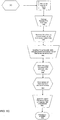
- FIG. 5 is a block diagram showing an exemplary method of fabricating an exemplary LiNb 20-25 MHz transducer with a TPX lens.
- the fabrication process is described below in three exemplary sections. First, the fabrication of matching layers and piezoelectric layer to form a stack is described. Second, the fabrication of the lens layer and a cyanoacrylate matching layer is described. Finally, bonding of the lens and cyanoacrylate layer to the transducer stack is described.
- a LiNb Crystal is prepared for the piezoelectric layer as shown in block 504.
- a 36 degree Y-Cut LiNb crystal is lapped to a thickness of 0.4 lambda of the desired center frequency to compensate for mass loading.
- the crystal is plated with 3000 A of gold using a suitable means such as E-Beam deposition or Sputtering.
- a suitable means such as E-Beam deposition or Sputtering.
- typically a thin layer of Cr or Ni can be used to improve adhesion of the gold layer.
- the gold side of the LiNb crystal is cleaned with Acetone. After cleaning, the crystal is placed in a clean place until further handling.
- a nano-particle and micro-particle loaded epoxy is prepared for 1 ⁇ 4 wave matching layers.
- a high impedance matching layer, having an impedance above about 8 MR is prepared in block 506.
- Creating a loaded epoxy composite with acoustic impedance over 8 MR is typically limited by the maximum volumetric ratio of powder that can be wetted by the epoxy. Achieving volumetric ratios of over 20 % with particles small enough to be compatible with a 25 MHz design is challenging due to the large surface area to volume ratio of fine powders. With a 20 % volumetric limitation and using tungsten powder, it is difficult to create composites with acoustic impedances over about 8 - 9 MR. See, e.g., Martha G. Grewe, T.R.
- a low viscosity epoxy (less than 1000 cps is preferred) allows for the greatest volumetric ratio of powder to be added to the epoxy before the mixture becomes too dry to use.
- An example of such an epoxy known in the art, is Epotek 301. See, e.g., Haifeng Wang, Tim Ritter, Wenwu Cao, and K. Kirk Shung, "Passive Materials for High Frequency Ultrasound Transducers", SPIE Conf. on Ultrasonic Transducer Engineering, San Diego, California, Feb. 1999, SPIE Vol. 3664 .
- the epoxy is mixed completely before addition of any powders.
- a volumetric ratio of 25% powder in an epoxy matrix is used.
- relatively large 5 ⁇ m particles are used.
- a sub-micron tungsten (W) powder mixed with the 5 ⁇ m powder to a ratio of 1:1 is also used. This is effective over a range of at least 1:6 to 2:1 by weight.
- the upper limit of density that can be achieved in a powder loaded epoxy is limited by the ability to wet the surface of all the powder particles. As the particle size increases, the ratio of the volume of the powdered material, to the surface area increases linearly.
- the volumetric ratio of powder to epoxy that can be sufficiently wetted to result in a void free mixture increases.
- the particle diameter can be small compared to the wavelength of the matrix (epoxy).
- the particle size can be sufficiently small that the composite contains at least 15 or more particles through its thickness.
- the exemplified use of a mixture of nano-particles with larger particles allows for high density loaded powders with both high volumetric fractions of the loading powder and excellent control over settling. Settling is controlled by adjusting the amount of nano-particles to control the viscosity and thixotropic index of the resulting paste.
- the nano-particles also provide that at any given cross section, the 1 ⁇ 4 wave layer (16.5 um thick at 25 MHz for example) has a high number of particles and an even spatial distribution of powder particles ( i.e. there are no large areas of epoxy between large particles as would be the case with just large particles).
- An exemplary W doped Epoxy preparation comprises a mixed batch of 3:1 vol. / vol. Epotek 301 epoxy to 50%:50% 5 ⁇ m: ⁇ 1 um tungsten powder. This is a highly thixotropic paste and is an 85% by weight tungsten mixture with a density of 5.7 g/cc and a volumetric fraction of 25% tungsten.
- the mixture can be weighed out as follows: 0.5 g of mixed 301 epoxy (0.1 g of hardener and 0.4 g of resin); 1.5 g of ⁇ 1 um W powder; 1.5 g of 5 um W powder.
- a medium acoustic impedance matching layer having an impedance between about 3.5 MR to 6 MR is fabricated as shown in block 514 by mixing lightweight particles with heavy particles.
- the creation of medium acoustic impedance matching layers can use high volumetric fractions of a single light particle to achieve mid and upper impedances in this range.
- using a single material, with a sufficiently small particle size to create medium acoustic impedance typically requires a difficult search for an appropriate density material available in a suitable powder grain size.
- High volumetric fractions making mixing, degassing, and spreading/application very difficult due to high viscosity and highly thixotropic pastes being created, which leads to manufacturing issues.
- the volumetric fraction of powder are typically be kept above 11% to keep attenuation low, often a compromise must be made between achieving the ideal acoustic impedance and ideal physical properties, or a new material must be sought and the process begun again.
- a solution is possible that decouples the problem of achieving the desired acoustic impedance from the issues of viscosity, wetting, and thixotropic index.
- a heavy material is mixed to a volumetric fraction resulting in the desired acoustic impedance, then light nano-particles are added until a desirable viscosity and thixotropic index are achieved (i.e., a paste that is easily wetted, but will not flow all over or settle.)
- a commercially available light weight nano particle of SiC may be used as the light weight particle.
- the acoustic impedance of the matching layer is controlled almost exclusively by the volumetric faction of the heavy powder, which would have significant settling issues at that fraction.
- the viscosity and consistency of the composite mixture and settling is controlled almost exclusively by the light weight powder.
- the light weight powder is selected so that its density is within between about 100% to 200% of the density of the desired composite density of the heavy powder-epoxy mixture.
- a 5.5% volumetric fraction of nano-particles of tungsten powder is used in a suitable room temperature cure low viscosity epoxy to achieve an acoustic impedance of between about 4.5 MR - 5 MR.
- SiC nano-particles are then added to achieve an exemplified 11% volumetric fraction.
- This exemplified mixture is easy to work with, wets very well, and does not settle appreciably over a 24 hour cure period during which the epoxy to sets.
- the mixture settles out completely in seconds, however, after the addition of the SiC, the mixture becomes thixotropic, and does not settle.
- the addition of SiC particles minimally changes the acoustic impedance, but significantly changes the viscosity and eliminates settling of the mixture. Any desired acoustic impedance can be achieved in the medium range while maintaining a desirable working property without settling, and without needing extremely high volumetric fractions using two readily obtainable powdered materials. Also due to the size of the nano-particles, attenuation and scattering are kept to a minimum, making this an exceptional matching layer.
- the W-Doped epoxy can be added to the stack as shown in block 508.
- Application of the matching layers requires careful attention, as air pockets in the matching layer can generally result in a malfunctioning stack. Air pockets near the interface of the piezoelectric crystal and the powder loaded epoxy can be detrimental.
- the loaded epoxy is spread evenly and air pockets are forced to the surface of the mixture.
- the thixotropic pastes used to make matching layers are difficult to 'flow' onto a part and normally require agitation to flow like a liquid.
- a vibrating manipulator for example, an engraver with a piece of 22 gauge wire attached to it
- the vibration encourages air pockets to rise to the surface of the paste, where they can be sanded away. This allows the use of highly thixotropic pastes that do not settle after they have been spread as desired.
- an engraver tip modified with 22 gauge hard temper copper wire L-Shaped tip is used to move the thixotropic paste smoothly over the surface for good wetting and promotion of the rising of air pockets to the surface.
- the engraver tip is used over the entire surface of the aperture and is set to a low amplitude high frequency setting (about 7,200 spm).
- the surface of the LiNb crystal is covered leaving a small part of the rim (about .25 mm) uncovered around the edge so that it can be used for a ground later. If epoxy is placed on the rim, it cannot be cleaned effectively without removing the whole batch off the face of the transducer.
- the epoxy is allowed to cure at room temperature and post cure at an elevated temperature as shown in block 510.
- Room temperature cure epoxies are used so that significant shrinkage of the layers, which can cause warping of the piezoelectric crystal, does not occur.
- a high Tg is preferred, so an epoxy is selected that is compatible with an elevated temperature post cure in an oven.
- the epoxy is allowed to cure at room temperature for about 18 hours or more (24 hours is preferred). Further, the cured epoxy is post cured in incubator for about 3 or more hours at 65 degrees C.
- the first matching layer is sanded and/or lapped as shown in block 510. Excess material is removed to achieve the 1 ⁇ 4 wave matching layers. Several methods (such as lapping or sanding, etc.) can be used to remove excess material leaving a 1 ⁇ 4 wave thickness matching layer.
- a second lower impedance layer is fabricated and applied as shown in block 514.
- a second medium acoustic impedance paste is applied to the first layer and the process of spreading, curing, and material removal is repeated to create the second 1 ⁇ 4 wave layer.
- a batch is mixed as follows: W powder doped epoxy using a 17:1 vol. / vol. or (51% W by weight) mixture of Epotek 301 and ⁇ 1 ⁇ m Tungsten powder. 50% of the mass of the mixture in ⁇ 1 um SiC powder is added and mixed until a smooth paste is achieved. Any lumps in the paste can be removed by mixing lightly in a mortar and pestle.
- the mixture may be weighted out as follows: 0.5 g of mixed 301 epoxy; 0.52 g of ⁇ 1 um W powder; 0.2 g of ⁇ 1 um SiC powder.
- the second layer is applied as with the 1st, using the L-shaped tip in the engraver for even spreading of the paste, and for good wetting.
- the mixture is allowed to cure at room temperature for about 18 - 24 hours, then post cured at 65 degrees for about 3 hours or more.
- the second matching layer is sanded and/or lapped as show in block 516.
- the support structure for the stack is prepared and the crystal is bonded to the support structure as shown in block 518 and 520.
- the stack is positioned in a housing.
- a Ultem 1000 (polyetherimide) insert can be used having an ID matching the desired transducer aperture and height and OD matching the specifications of the desired Ti transducer housing so that the top of the insert is about 1.5 mm below the rim of the Ti housing.
- the front face of the insert is cleaned and inspected so that it is clean and free of burrs or flashing.
- the insert can be cleaned with the ultrasonic cleaner and detergent initially and can be cleaned just before use with isopropyl alcohol.
- a small quantity of a suitable low temp cure medium viscosity epoxy (e.g ., Loctite E-20 HP) is prepared and is applied to the cleansed front face of the insert in a very thin coat using a sponge tipped swab.
- the epoxy is not applied so heavily as to form a meniscus across the wall thickness of the insert.
- the crystal is placed, with the stack side up, onto the epoxy covered face of the insert and is centered on the insert.
- the lithium niobate crystal is applied to the insert by using a vacuum pick-up tool.
- a small amount of force is applied to push the crystal onto the face of the insert, which causes the epoxy to flow toward the edges of the underlying insert.
- the centered crystal is placed into a incubator for curing at about 40 degrees C for about 3 hours.
- the insert/crystal assembly is inspected to ensure that the crystal is centered and completely adhered to the insert. Subsequently, the periphery of the insert/crystal assembly is cleaned. The non-increased diameter of the Ultem insert is checked by sliding the part into an exemplary housing.
- the acoustic stack can be housed onto a suitable support structure and a rear electrode and suitably attenuating backing material can be applied as shown in blocks 522 and 524. These functions are can be combined by using conductive epoxy as a backing layer.
- the exemplified insert/crystal assembly is normally placed in a clean smooth work surface crystal layer down.
- the back cavity is filled with Ablebond 16-1 silver conductive epoxy.
- the cavity is filled by first placing a dollop of epoxy in the center of the cavity using an epoxy syringe and applicator tip. The epoxy is applied to the entire back face of the crystal making sure not to allow any air pockets to be trapped in the backing material. The epoxy syringe is used to continue filling with the tip of the applicator below the surface of the epoxy so that no air pockets are created in the epoxy when filling.
- the cavity is filled until the conductive epoxy is about 0.5 mm below the rim of the insert:
- the backed stack can now be housed in a suitable housing depending on the application that the device is intended for, taking into consideration, weight budgets, temperature, and RF shielding, etc. and is sealed as shown in blocks 526 and 528.
- the pill is placed onto the Housing fixture with the uncured epoxy up. Several small dots of Loctite E-20 HP are applied to the back rim of the pill such that the dots do not flow together.
- a completed housing is laid over the pill until the pill makes contact with the back of the housing.
- the fixture clamp is placed over the housing to hold it in place, and allowed to cure at room temperature for about 18 hours or more.
- the assembly is then placed into an incubator at 65 degrees for about 3 hours for post curing.
- the face of the pill is oriented parallel to the floor and pointing down to help prevent the backing layer from flowing inside the housing.
- a sealing layer can be applied.
- a bead of epoxy is applied around the perimeter of the crystal so that a continuous smooth surface exists between the crystal and the Ti housing.
- Epotek 301 epoxy is placed around the perimeter of the LiNb crystal and the inside diameter of the housing.
- the surface of the crystal is about 1.25 mm below chamfer on the Ti housing in order to desirably achieve a negative meniscus of epoxy between the crystal and the Ti housing.
- Both the crystal and the Ti are clean and free of epoxy on their surfaces so that gold can be sputtered onto both surfaces.
- a high magnification (about 20 times and preferably more) is used to place the epoxy bead.
- the epoxy can be applied at three locations around the perimeter and allowed to run around the perimeter using gravity and capillary action.
- a piece of fine gauge wire (26 gauge or so) can be attached to the end of a sharp Q-tip to improve control to help the glue to flow around the entire perimeter.
- the resultant construct is allowed to cure at room temperature for about 12 - 18 hours.
- the sealing procedure can be repeated and the construct is allowed to cure at room temp for about 18 hours then is incubated at 65 degrees for a post cure of about 3 hours.
- the rim of the Ti housing is inspected for epoxy. Any epoxy found on the rim is removed.
- a ground connection to a signal return path is made to the exposed gold rim of the acoustic stack as shown in block 530.
- attaching such an electrode including sputtering, conductive inks and epoxies, direct mechanical contact with a good conductor, etc.
- the stack in one example, can then be bonded to a third low impedance matching layer and a lens.
- a well-matched lens is selected.
- the lens is closely matched to water in terms of acoustic impedance to provide for a reduction of reverberation artifacts.
- the lens material can be low in attenuation and have a speed of sound sufficiently different from water so as to be able to create a focusing effect without extreme curvature.
- many transducer designs make use of cured piezoelectric elements, or array structures as alternatives to lenses.
- TPX a preferred lens material that has an acoustic match to water.
- TPX is a member of the polyolefin family and has a close acoustic impedance match to water and tissue compared to most plastics.
- TPX has an acoustic impedance of between about 1.78 MR to 1.85 MR. See , e.g ., Alan R. Selfridge, "Approximate Material Properties in Isotropic Materials," IEE Trans. Sonics and Ultrasonics, Vol. SU-32, No.3, May 1985 .
- TPX is difficult to bond with epoxies and most other adhesives.
- the most common use of TPX in industry is as a release film. That is, TPX is recognized as a material that most things will not stick to. While some surface preparation techniques can be used to enhance bond strength, in fact, even with adhesion promoters and primers, or coronal etching TPX is often not bondable in a demanding application and must be jointed either mechanically or heat sealed or welded. See, Timothy Ritter, K. Kirk Shung, Xuecang Geng, Pat Lopath, Richard Tutwiler, and Thomas Shrout," Proceedings of SPIE -- Volume 3664 Medical Imaging 1999: Ultrasonic Transducer Engineering, K. Kirk Shung, Editor, June 1999, pp. 67-75 .
- the bondline between a lens and an acoustic stack in an imaging transducer can experience temperature swings of over 40 degrees Celsius in a few minutes, and rapid cooling routinely during use. In addition, it is constantly bombarded with ultrasonic energy. Weakness in bonding generally results in delamination and dead spots in the transducer. For this reason, high quality bond lines are desired for transducer construction.
- the lens remains in contact with the stack at all times. Even a thin disbond can result in a dead spot in the transducer.
- CA adhesive systems are bonded to the TPX lens.
- a suitable primer such as, for example and not meant to be limiting, Verik AC77, some toluene based primers, and the like
- CA can form a robust bond to TPX.
- cyanoacrylate's curing characteristics being very sudden and dependant on substrate and environmental conditions, CA has not been used in transducer stacks. The glue can snap cure occurs suddenly at the very thin bond lines used in making a high frequency ultrasonic stack.
- the addition of bondline spacers is often not used with CA adhesives as they cause instant curing of the material due to their large surface areas.
- CA cannot be powder loaded for the same reason, further making it an unlikely candidate for transducer manufacturing. Moreover, acoustic properties of CA have not been available in the literature, as the material cannot be cured in a thick enough section for standard testing. Furthermore, material properties that may be used to acoustically model CA have been unavailable for similar reasons.
- CA can be cured over a narrow range of thickness.
- the range over which CA can be cured can be used for forming 1 ⁇ 4 wave matching layers for frequencies from 5 MHz up to over 60 MHz.
- the acoustic properties of CA were determined by using it as a matching layer and were correlated to a model using PiezoCAD software based on the KLM model available from Sonic Concepts, Woodinville, Washington USA. The results showed that CA can be used as a matching layer with acoustic impedance of between about 2.5 MR -2.8 MR.
- One exemplary method to bond TPX to a 1 ⁇ 4 wave matching system makes use of CA.
- the bond between the TPX layer and the CA layer was tested and results indicated that the interface between the CA layer and TPX layer is at least as strong as the TPX itself.
- it is not suitable for bonding directly to the stack, as the bond thickness cannot be controlled, and voids and misalignment are likely, which can ruin an almost complete transponder stack at the least stages of assembly.
- a 1 ⁇ 4 wave thick cured layer of CA is created on the back (flat side) of the TPX lens layer, and the formed construct is then bonded to the upper surface of the previously formed stack with a traditional epoxy.
- the epoxy bonds readily to the CA layer, and the CA layer, which is, in turn, bonded to the TPX lens layer.
- the CA layer forms a 1 ⁇ 4 wave matching layer from the top of the stack to the TPX lens layer.
- a quantity of CA glue such as, for example, Verik PR40, is coated onto the back of the TPX lens by means of an aluminum foil release layer and wire spacers as shown in blocks 534 and 536.
- the release film is placed onto a flat surface (preferably a vacuum plate so that the foil is flat).
- the aluminum foil is clean and free of oil and moisture.
- Wires are laid in a pattern onto the release film.
- the wires are positioned in a radial pattern so that the wires do not meet at their common vertex. These wires are used as spacers for the layer of CA.
- a wire having a diameter of about 25 ⁇ m is used to form a CA layer having a resultant thickness about 23 ⁇ m - 25 ⁇ m.
- This is slightly thicker than the desired 1 ⁇ 4 wave thickness for CA, which would be between about 21 to 23 ⁇ m for a 25 MHz design frequency transducer.
- the longitudinal velocity in CA is between about 2100 m/s to 2200 m/s.
- the 1 - 3 ⁇ m surplus material is removed during a later abrasion process which also acts to prepare the surface of the CA layer to improve adhesion of the epoxy used to glue the lens layer having the adhered CA layer to the underlying stack.
- the back face of the TPX lens layer is abraded with a suitable grit SiC sandpaper to improve the surface for adhesion and is treated with a suitable CA polyolefin primer, such as, for example, Verik AC77, toluene based primers, and the like, as shown in block 532.
- a suitable CA polyolefin primer such as, for example, Verik AC77, toluene based primers, and the like.
- the back of the lens is then covered with a generous amount of CA so that substantially the entire surface is wetted as shown in block 536.
- CA will not cure quickly when allowed to form a relatively thick meniscus on the back of the lens, and so the generous amount of CA provides sufficient time to place the lens onto the prepared release film/wire arrangement.
- the lens layer with the applied CA, is placed onto the release film and pressed lightly so that the lens "sandwiches" the wires between the underlying release film and the lens layer as shown in block 538.
- the lens and the attached release film is removed from the vacuum plate and the release film is peeled off the lens layer as shown in block 542.
- the CA layer is allowed to cure for about 24 hours, as shown in block 540, at which time 1 - 3 ⁇ m of CA are then removed with SiC sand paper to abrade the surface of the newly formed CA layer in preparation for bonding to the stack as shown in block 544.
- the composite formed lens layer/CA layer is bonded to the transducer stack as shown in blocks 548, 550 and 552.
- a suitable low viscosity RT cure epoxy such as Epotek 301, with an acoustic impedance value close to that of the CA layer is used to glue the composite lens layer/CA layer to the underlying stack.
- the lens is held in place using a fixture to maintain pressure of at least about 100 kPa during curing of the epoxy.
- An extended post cure at an elevated temperature using a external heat source is used for curing epoxy at such a thin bondline, which ensures the production of a bondline of less than 5 ⁇ m, and preferably from 1 ⁇ m - 3 ⁇ m.
- the above exemplary methods can be used to create a transducer stack wherein the piezoelectric layer has a center frequency range of from about 5 MHz to about 60 MHz or higher.
- Such a transducer can be used to image small animals, including the rat, using high transmit frequencies (greater than or equal to 20MHz).
- Example 2 General High Frequency Design for an Exemplified Broadband (85 - 95 % - 6dB bandwidth) LiNb Transducer with TPX lens
- Table 1 shows the different layers that make up an exemplary transducer stack.
- the stack design can be used for transducers with a center frequency from about 20 MHz to over 60 MHz.
- the design center frequency f D is chosen to be higher than the desired operating center frequency of the device f 0 to compensate for mass loading which reduces the center frequency of a device.
- f D is the frequency that the device would operate at in air with no lens and air backing.
Landscapes
- Health & Medical Sciences (AREA)
- Life Sciences & Earth Sciences (AREA)
- Engineering & Computer Science (AREA)
- Physics & Mathematics (AREA)
- Medical Informatics (AREA)
- Animal Behavior & Ethology (AREA)
- Radiology & Medical Imaging (AREA)
- Nuclear Medicine, Radiotherapy & Molecular Imaging (AREA)
- Biomedical Technology (AREA)
- Heart & Thoracic Surgery (AREA)
- Biophysics (AREA)
- Molecular Biology (AREA)
- Surgery (AREA)
- Pathology (AREA)
- General Health & Medical Sciences (AREA)
- Public Health (AREA)
- Veterinary Medicine (AREA)
- Acoustics & Sound (AREA)
- Mechanical Engineering (AREA)
- Multimedia (AREA)
- Transducers For Ultrasonic Waves (AREA)
- Ultra Sonic Daignosis Equipment (AREA)
Claims (30)
- Pile de transducteurs ultrasonores (100), comprenant :une pluralité de couches, chaque couche ayant une surface supérieure et une surface inférieure opposée ; dans laquelle la pluralité de couches inclut :caractérisé en ce queune couche d'adaptation (108, 110, 112) qui comprend un matériau composite comprenant un matériau de matrice chargé avec une première quantité de particules de taille micrométrique et une deuxième quantité de particules de taille nanométrique ; etune couche piézoélectrique (102) dans laquelle la surface inférieure de la couche d'adaptation recouvre la surface supérieure de la couche piézoélectrique ;la couche piézoélectrique est configurée pour produire des ultrasons à une fréquence centrale d'au moins environ 20 mégahertz (MHz) à travers la couche d'adaptation ;les particules de taille micrométrique et nanométrique comprennent entre environ 10% et environ 35% du matériau composite sur une base volumique ; etles particules de taille nanométrique empêchent la décantation des particules de taille micrométrique dans le matériau de matrice.
- Pile de transducteurs ultrasonores (100) selon la revendication 1, dans laquelle les particules de taille nanométrique ont une plus grande dimension allongée qui est d'environ 800 nm ou moins.
- Pile de transducteurs ultrasonores (100) selon la revendication 1 ou 2, dans laquelle les particules de taille micrométrique et nanométrique comprennent du métal à haute densité, préférablement étant sélectionné dans un groupe constitué : de tungstène, d'or, ou de platine ou d'un mélange de ceux-ci.
- Pile de transducteurs ultrasonores (100) selon la revendication 1 ou 2, dans laquelle les particules de taille micrométrique et nanométrique comprennent de la céramique à haute densité.
- Pile de transducteurs ultrasonores (100) selon l'une quelconque des revendications précédentes, dans laquelle les particules de taille micrométrique et nanométrique sont chargées dans le matériau de matrice dans un rapport numérique entre environ 5:1 à environ 1:5 parties de particules de taille micrométrique sur les particules de taille nanométrique en poids, préférablement dans un rapport numérique d'environ 1:1 particules de taille micrométrique sur les particules de taille nanométrique en poids.
- Pile de transducteurs ultrasonores (100) selon l'une quelconque des revendications précédentes, dans laquelle les particules de taille nanométrique et les particules de taille micrométrique comprennent environ 25% à environ 30% du matériau composite sur une base volumique ; et préférablement environ 25% de matériau composite sur une base volumique.
- Pile de transducteurs ultrasonores (100) selon l'une quelconque des revendications précédentes, dans laquelle l'impédance acoustique de la couche d'adaptation (108) est entre environ 7,0 MégaRayles à environ 14,0 MégaRayles, préférablement environ 10 MégaRayles.
- Pile de transducteurs ultrasonores (100) selon l'une quelconque des revendications précédentes, dans laquelle l'épaisseur de la couche d'adaptation (108, 110, 112) est entre environ 4 microns et 30 microns dans la dimension d'élévation de la pile de transducteurs ultrasonores.
- Pile de transducteurs ultrasonores (100) selon l'une quelconque des revendications précédentes, dans laquelle la vitesse du son dans la couche d'adaptation (108, 110, 112) est entre environ 1000 mètres/seconde et environ 3000 mètres/seconde ; préférablement entre environ 1200 mètres/seconde et environ 2100 mètres/seconde; et plus préférablement environ 1600 mètres/seconde.
- Pile de transducteurs ultrasonores (100) comprenant :une pluralité de couches, chaque couche ayant une surface supérieure et une surface inférieure opposée, dans laquelle la pluralité de couches inclut :une couche d'adaptation (108, 110, 112) qui comprend une matériau composite comprenant un matériau de matrice chargé avec une pluralité de premières particules lourdes et une pluralité de deuxièmes particules légères ; etune couche piézoélectrique (102), dans laquelle la surface inférieure de la couche d'adaptation recouvre la surface supérieure de la couche piézoélectrique ;caractérisée en ce quela couche piézoélectrique est configurée pour générer des ultrasons à une fréquence centrale d'au moins environ 20 mégahertz (MHz) à travers la couche d'adaptation ;la pluralité de premières particules lourdes sont localisées dans le matériau de matrice dans une première quantité pour atteindre une impédance acoustique souhaitée ;la pluralité de deuxièmes particules légères sont chargées dans la matériau de matrice dans une deuxième quantité pour contrôler la viscosité et l'index thixotropique du matériau composite et pour créer une distribution régulière des particules lourdes dans le matériau de matrice ; etla pluralité de deuxièmes particules légères sont sélectionnées pour avoir une densité entre environ 100% et 200% d'une densité combinée souhaitée des premières particules lourdes et du matériau de matrice.
- Pile de transducteurs ultrasonores (100) selon la revendication 10, dans laquelle la vitesse du son dans la couche d'adaptation (108, 110, 112) est entre environ 1500 mètres/seconde et environ 4500 mètres/seconde, préférablement entre environ 1800 mètres/seconde et environ 2500 mètres/seconde.
- Pile de transducteurs ultrasonores (100) selon la revendication 10, dans laquelle les premières particules lourdes comprennent des particules ayant une masse volumique supérieure ou égale à environ 4,0 grammes par centimètre cube, préférablement au moins environ 10,0 grammes par centimètre cube.
- Pile de transducteurs ultrasonores (100) selon la revendication 10, dans laquelle les deuxièmes particules légères ont une masse volumique inférieure ou égale à environ 4,0 grammes par centimètre cube, préférablement entre environ 2,5 grammes par centimètre cube et environ 4,0 grammes par centimètre cube.
- Pile de transducteurs ultrasonores (100) selon l'une quelconque des revendications 10 à 13, dans laquelle la pluralité de particules comprennent au moins environ 11% du matériau composite en volume, préférablement entre environ 11% à environ 20% du matériau composite en volume.
- Pile de transducteurs ultrasonores (100) selon la revendication 14, dans laquelle environ 5,5% du matériau composite en volume comprend une pluralité de premières particules lourdes de taille nanométrique et dans laquelle environ 5,5% du matériau composite en volume comprend une pluralité de deuxièmes particules légères de taille nanométrique.
- Pile de transducteurs ultrasonores (100) selon l'une quelconque des revendications 10 à 15, dans laquelle les premières particules lourdes sont sélectionnées dans un groupe constitué de particules de tungstène, de particules de titano-zirconate de plomb (PZT), ou d'un mélange de celles-ci, et dans laquelle les deuxièmes particules légères sont sélectionnées dans le groupe constitué de particules de carbite de silicone, de particules d'alumine, ou d'un mélange de celles-ci.
- Pile de transducteurs ultrasonores (100) selon l'une quelconque des revendications 10 à 16, dans laquelle les premières particules lourdes et deuxièmes particules légères ont une taille inférieure à 1 micron, et/ou dans laquelle l'impédance acoustique de la couche d'adaptation (110) est entre environ 3,0 MégaRayles et environ 7,0 MégaRayles, préférablement environ 4,5 MégaRayles.
- Pile de transducteurs ultrasonores (100) selon l'une quelconque des revendications 10 à 17, dans laquelle l'épaisseur de la couche d'adaptation (108, 110, 112) est entre environ 4,0 microns et environ 30,0 microns dans la dimension d'élévation de la pile de transducteurs ultrasonores.
- Pile de transducteurs ultrasonores (100) selon l'une quelconque des revendications précédentes, dans laquelle la couche piézoélectrique (102) est configurée pour générer des ultrasons à une fréquence centrale d'au moins environ 25 MHz, 30 MHz, 35 MHz, 40 MHz, 45 MHz, 50 MHz, 55 MHz, 60 MHz, 65 MHz, 70 MHz ou plus pour une transmission à travers la couche d'adaptation (108, 110, 112).
- Pile à transducteurs ultrasonores (100) selon l'une quelconque des revendications précédentes, dans laquelle la couche piézoélectrique (102) est sélectionnée dans un groupe constitué de niobate de lithium, de PZT, ou d'un mélange de ceux-ci.
- Pile à transducteurs ultrasonores (100) selon l'une quelconque des revendications 10 à 18, dans laquelle la pile comprend en outre une deuxième couche d'adaptation (108) ayant une impédance plus élevée que l'impédance de la couche d'adaptation qui est une première couche d'adaptation (110, 112), et dans laquelle la deuxième couche d'adaptation est positionnée entre la surface supérieure de la couche piézoélectrique (102) et la surface inférieure de la première couche d'adaptation.
- Pile à transducteurs ultrasonores selon la revendication 21, dans laquelle la couche piézoélectrique (102) est configurée pour générer des ultrasons ayant une fréquence centrale d'au moins environ 20 mégahertz (MHz) préférablement au moins environ 25 MHz, 30 MHz, 35 MHz, 40 MHz, 45 MHz, 50 MHz, 55 MHz, 60 MHz, 65 MHz, 70 MHz ou plus pour une transmission à travers la deuxième couche d'adaptation et ensuite à travers la première couche d'adaptation.
- Pile à transducteurs ultrasonores selon la revendication 21 ou 22, dans laquelle la deuxième couche d'adaptation est la même que la première couche d'adaptation.
- Pile à transducteurs ultrasonores (100) selon l'une quelconque des revendications précédentes, dans laquelle la couche d'adaptation (108, 110, 112) est une couche d'adaptation de ¼ de longueur d'onde acoustique.
- Pile à transducteurs ultrasonores (100) selon l'une quelconque des revendications précédentes, dans laquelle les particules chargées ont une plus grande dimension allongée qui est inférieure à l'épaisseur de la couche d'adaptation (108, 110, 112).
- Pile à transducteurs ultrasonores (100) selon l'une quelconque des revendications précédentes, dans laquelle le matériau de matrice est un polymère, préférablement un époxy, et plus préférablement dans laquelle l'époxy est un époxy durcissant à température ambiante à faible viscosité avec un Tg au-dessus de la température de fonctionnement maximale du transducteur.
- Pile à transducteurs ultrasonores (100) selon l'une quelconque des revendications précédentes, dans laquelle la couche piézoélectrique (102) a une impédance acoustique d'au moins 20 MégaRayles.
- Procédé pour produire une pile à transducteurs ultrasonores (100) ayant une pluralité de couches, incluant une couche d'adaptation (108, 110, 112) et une couche piézoélectrique (102), le procédé comprenant :fournir un matériau de matrice ;fournir une pluralité de particules de taille micrométrique ;fournir une pluralité de particules de taille nanométrique ; etcharger le matériau de matrice avec une première quantité de particules de taille micrométrique et une deuxième quantité de particules de taille nanométrique pour former un matériau composite, dans lequel le matériau composite est utilisé pour produire la couche d'adaptation de la pile à transducteurs ultrasonores ;caractérisé en ce queles particules de taille micrométrique et les particules de taille nanométrique comprennent entre environ 10% et environ 35% du matériau composite sur une base volumique ;les particules de taille nanométrique empêchent la décantation des particules de taille micrométrique dans le matériau de matrice ; etla couche piézoélectrique est configurée pour générer des ultrasons à des fréquences d'au moins environ 20 mégahertz (MHz) à travers la couche d'adaptation.
- Procédé selon la revendication 28, dans lequel les particules de taille micrométrique et les particules de taille nanométrique sont composées du même matériau de base ; ou dans lequel les particules de taille micrométrique et les particules de taille nanométrique sont composées de matériaux de base différents.
- Procédé pour produire une pile à transducteurs ultrasonores (100) ayant une pluralité de couches, incluant une couche d'adaptation (108, 110, 112) et une couche piézoélectrique (102), le procédé comprenant :fournir un matériau de matrice ;fournir une pluralité de premières particules lourdes ;fournir une pluralité de deuxièmes particules légères ; etcharger le matériau de matrice avec une pluralité des premières particules lourdes et une pluralité des deuxièmes particules légères pour former un matériau composite, dans lequel le matériau composite est utilisé pour produire la couche d'adaptation de la pile à transducteurs ultrasonores ;caractérisé en ce quela pluralité de premières particules lourdes sont chargées dans le matériau de matrice dans une première quantité pour atteindre une impédance acoustique souhaitée ;la pluralité de deuxièmes particules légères sont chargées dans le matériau de matrice dans une deuxième quantité pour contrôler la viscosité et l'index thixotropique du matériau composite et pour créer une distribution uniforme des particules lourdes dans le matériau de matrice ;la pluralité de deuxièmes particules légères sont sélectionnées pour avoir une densité entre environ 100% et 200% d'une densité combinée souhaitée des premières particules lourdes et du matériau de matrice ; etla couche piézoélectrique est configurée pour générer des ultrasons à des fréquences d'au moins 20 mégahertz (MHz) à travers la couche d'adaptation.
Priority Applications (1)
| Application Number | Priority Date | Filing Date | Title |
|---|---|---|---|
| EP16195016.7A EP3151238B1 (fr) | 2006-03-02 | 2007-03-01 | Transducteur ultrasonique et procédé pour sa fabrication |
Applications Claiming Priority (2)
| Application Number | Priority Date | Filing Date | Title |
|---|---|---|---|
| US11/366,144 US7808156B2 (en) | 2006-03-02 | 2006-03-02 | Ultrasonic matching layer and transducer |
| PCT/US2007/005301 WO2007103144A2 (fr) | 2006-03-02 | 2007-03-01 | Couche d'adaptation ultrasonore et transducteur associé |
Related Child Applications (2)
| Application Number | Title | Priority Date | Filing Date |
|---|---|---|---|
| EP16195016.7A Division EP3151238B1 (fr) | 2006-03-02 | 2007-03-01 | Transducteur ultrasonique et procédé pour sa fabrication |
| EP16195016.7A Division-Into EP3151238B1 (fr) | 2006-03-02 | 2007-03-01 | Transducteur ultrasonique et procédé pour sa fabrication |
Publications (3)
| Publication Number | Publication Date |
|---|---|
| EP2004064A2 EP2004064A2 (fr) | 2008-12-24 |
| EP2004064A4 EP2004064A4 (fr) | 2012-05-02 |
| EP2004064B1 true EP2004064B1 (fr) | 2017-02-22 |
Family
ID=38470885
Family Applications (2)
| Application Number | Title | Priority Date | Filing Date |
|---|---|---|---|
| EP07752029.4A Not-in-force EP2004064B1 (fr) | 2006-03-02 | 2007-03-01 | Transducteur ultrasonore avec couche d'adaptation en matériau composite |
| EP16195016.7A Not-in-force EP3151238B1 (fr) | 2006-03-02 | 2007-03-01 | Transducteur ultrasonique et procédé pour sa fabrication |
Family Applications After (1)
| Application Number | Title | Priority Date | Filing Date |
|---|---|---|---|
| EP16195016.7A Not-in-force EP3151238B1 (fr) | 2006-03-02 | 2007-03-01 | Transducteur ultrasonique et procédé pour sa fabrication |
Country Status (6)
| Country | Link |
|---|---|
| US (1) | US7808156B2 (fr) |
| EP (2) | EP2004064B1 (fr) |
| JP (3) | JP5415086B2 (fr) |
| CN (2) | CN101442940B (fr) |
| CA (1) | CA2644227C (fr) |
| WO (1) | WO2007103144A2 (fr) |
Cited By (3)
| Publication number | Priority date | Publication date | Assignee | Title |
|---|---|---|---|---|
| EP3706436B1 (fr) * | 2017-11-01 | 2023-09-27 | FUJIFILM Corporation | Composition de résine pour couche d'adaptation acoustique, produit durci, feuille d'adaptation acoustique, sonde d'onde acoustique, dispositif de mesure d'onde acoustique, procédé de production de sonde d'onde acoustique |
| KR20240061954A (ko) * | 2022-11-01 | 2024-05-08 | 포항공과대학교 산학협력단 | 고감도 고대역폭 단일공진 투명 초음파 트랜스듀서 및 그 제조 방법 |
| EP4120695B1 (fr) * | 2017-11-01 | 2024-05-29 | FUJIFILM Corporation | Ensemble de matériaux pour couche d'adaptation acoustique |
Families Citing this family (43)
| Publication number | Priority date | Publication date | Assignee | Title |
|---|---|---|---|---|
| US7750536B2 (en) | 2006-03-02 | 2010-07-06 | Visualsonics Inc. | High frequency ultrasonic transducer and matching layer comprising cyanoacrylate |
| US7808156B2 (en) | 2006-03-02 | 2010-10-05 | Visualsonics Inc. | Ultrasonic matching layer and transducer |
| DE102008014120A1 (de) * | 2008-03-13 | 2009-09-24 | Fraunhofer-Gesellschaft zur Förderung der angewandten Forschung e.V. | Ultraschallwandler mit akustischer Anpassungsschicht für hohe Ultraschallfrequenzen sowie Verfahren zur Herstellung der Anpassungsschicht |
| US8181523B2 (en) * | 2008-07-22 | 2012-05-22 | Nuovo Pignone S.P.A. | Ultrasound inspection methods for noisy cast materials and related probes |
| US9184369B2 (en) | 2008-09-18 | 2015-11-10 | Fujifilm Sonosite, Inc. | Methods for manufacturing ultrasound transducers and other components |
| US9173047B2 (en) | 2008-09-18 | 2015-10-27 | Fujifilm Sonosite, Inc. | Methods for manufacturing ultrasound transducers and other components |
| US8316518B2 (en) | 2008-09-18 | 2012-11-27 | Visualsonics Inc. | Methods for manufacturing ultrasound transducers and other components |
| US7905007B2 (en) * | 2009-03-18 | 2011-03-15 | General Electric Company | Method for forming a matching layer structure of an acoustic stack |
| JP2011062224A (ja) * | 2009-09-15 | 2011-03-31 | Fujifilm Corp | 超音波トランスデューサ及び超音波プローブ |
| JP2011077572A (ja) * | 2009-09-29 | 2011-04-14 | Fujifilm Corp | 超音波トランスデューサ及びその製造方法、並びに超音波プローブ |
| JP2011067485A (ja) * | 2009-09-28 | 2011-04-07 | Fujifilm Corp | 超音波トランスデューサ及び超音波プローブ |
| EP2444166A1 (fr) * | 2009-09-15 | 2012-04-25 | Fujifilm Corporation | Transducteur ultrasonique, sonde ultrasonique et procédé de production |
| JP5574050B2 (ja) | 2011-12-06 | 2014-08-20 | 株式会社村田製作所 | 超音波トランスデューサー |
| KR101477544B1 (ko) * | 2012-01-02 | 2014-12-31 | 삼성전자주식회사 | 초음파 트랜스듀서, 초음파 프로브, 및 초음파 진단장치 |
| US9804126B2 (en) | 2012-09-04 | 2017-10-31 | Veeco Instruments Inc. | Apparatus and method for improved acoustical transformation |
| US9211110B2 (en) | 2013-03-15 | 2015-12-15 | The Regents Of The University Of Michigan | Lung ventillation measurements using ultrasound |
| JP5524378B1 (ja) * | 2013-03-15 | 2014-06-18 | 株式会社又進 | 高温用超音波センサ |
| US9494453B2 (en) | 2013-03-25 | 2016-11-15 | Woojin Inc. | Ultrasonic sensor for high temperature and manufacturing method thereof |
| EP3014898B1 (fr) | 2013-06-24 | 2024-04-03 | ZetrOZ Systems, LLC | Transducteur ultrasonore à large bande, compact, à basse fréquence et faible impédance et procédés correspondants |
| JP6621745B2 (ja) * | 2013-11-22 | 2019-12-18 | サニーブルック ヘルス サイエンシーズ センター | 空間的にセグメント化された表面を有するバッキングを有する超音波トランスデューサ |
| WO2015095721A1 (fr) * | 2013-12-20 | 2015-06-25 | Fujifilm Sonosite, Inc. | Transducteurs à ultrasons haute-fréquence |
| CN103796149B (zh) * | 2014-02-14 | 2017-02-22 | 南京大学 | 一种尖劈状声学匹配层的制作方法 |
| CA2942379C (fr) * | 2014-03-12 | 2021-08-24 | Fujifilm Sonosite, Inc. | Transducteur a ultrasons haute frequence ayant une lentille ultrasonore avec une couche d'adaptation centrale integree |
| US11007686B2 (en) * | 2014-10-01 | 2021-05-18 | Surf Technology As | Ultrasound transducer matching layers and method of manufacturing |
| KR102457217B1 (ko) * | 2014-12-26 | 2022-10-21 | 삼성메디슨 주식회사 | 프로브 및 프로브의 제조방법 |
| JP6528504B2 (ja) * | 2015-03-31 | 2019-06-12 | コニカミノルタ株式会社 | 超音波振動子およびその製造方法ならびに超音波探触子 |
| CN105381943B (zh) * | 2015-10-14 | 2018-02-09 | 深圳市理邦精密仪器股份有限公司 | 超声换能器、渐变声阻抗匹配层及其制作方法 |
| US10736606B2 (en) * | 2015-11-10 | 2020-08-11 | Koninklijke Philips N.V. | Acoustic window layer for an ultrasound array |
| US10413272B2 (en) * | 2016-03-08 | 2019-09-17 | Covidien Lp | Surgical tool with flex circuit ultrasound sensor |
| CN108731716A (zh) * | 2017-04-13 | 2018-11-02 | 南昌欧菲生物识别技术有限公司 | 超声波传感器及电子装置 |
| US11480702B2 (en) * | 2018-06-27 | 2022-10-25 | Halliburton Energy Services, Inc. | Ultrasonic transducer with reduced backing reflection |
| EP3949865B1 (fr) | 2019-03-29 | 2024-02-21 | FUJIFILM Corporation | Feuille d'adaptation acoustique, composition pour couche d'adaptation acoustique, sonde d'onde acoustique, dispositif de mesure d'onde acoustique et procédé de fabrication de sonde d'onde acoustique |
| CN112438750B (zh) * | 2019-09-04 | 2024-12-27 | 深圳迈瑞生物医疗电子股份有限公司 | 一种超声探头 |
| CN112040382B (zh) * | 2020-08-10 | 2021-07-30 | 上海船舶电子设备研究所(中国船舶重工集团公司第七二六研究所) | 基于声阻抗梯度匹配层的高频宽带水声换能器 |
| WO2022070927A1 (fr) * | 2020-09-30 | 2022-04-07 | 富士フイルム株式会社 | Matériau de couche d'adaptation acoustique, feuille d'adaptation acoustique, composition destinée à former une feuille d'adaptation acoustique, sonde d'onde acoustique, dispositif de mesure d'onde acoustique, et procédés de production de matériau de couche d'adaptation acoustique et de sonde d'onde acoustique |
| JP7680877B2 (ja) * | 2021-05-06 | 2025-05-21 | 富士フイルム株式会社 | 音響カプラ、超音波画像処理方法、及び超音波撮像装置 |
| US11715321B2 (en) | 2021-05-13 | 2023-08-01 | Apple Inc. | Geometric structures for acoustic impedance matching and improved touch sensing and fingerprint imaging |
| EP4412252A4 (fr) * | 2021-09-30 | 2024-12-25 | FUJIFILM Corporation | Matériau stratifié d'adaptation acoustique, feuille d'adaptation acoustique, composition pour matériau stratifié d'adaptation acoustique, sonde à ondes acoustiques, dispositif de mesure d'ondes acoustiques et procédé de fabrication de sonde à ondes acoustiques |
| CN117546484A (zh) * | 2021-09-30 | 2024-02-09 | 富士胶片株式会社 | 声匹配层材料、声匹配片、声匹配层材料用组合物、声波探头、声波测定装置及声波探头的制造方法 |
| CN114886460B (zh) * | 2022-03-24 | 2025-05-13 | 深圳迈瑞生物医疗电子股份有限公司 | 线阵式超声探头 |
| ES2958164A1 (es) * | 2022-07-05 | 2024-02-02 | Consejo Superior Investigacion | Un método de fabricación de un material compuesto pasivo para un transductor ultrasónico |
| CN115318605B (zh) * | 2022-07-22 | 2023-09-08 | 东北大学 | 变频超声换能器自动匹配方法 |
| CN120714884A (zh) * | 2024-03-29 | 2025-09-30 | 深圳半岛医疗集团股份有限公司 | 一种超声换能器单元、阵列及超声治疗仪 |
Family Cites Families (54)
| Publication number | Priority date | Publication date | Assignee | Title |
|---|---|---|---|---|
| JPS59171296A (ja) * | 1983-03-17 | 1984-09-27 | Matsushita Electric Ind Co Ltd | 超音波トランスジユ−サ |
| JPS60100070A (ja) * | 1983-11-04 | 1985-06-03 | Matsushita Electric Ind Co Ltd | 超音波送受波器 |
| JPS59171295A (ja) * | 1983-03-17 | 1984-09-27 | Matsushita Electric Ind Co Ltd | 超音波トランスジユ−サ |
| US4523122A (en) * | 1983-03-17 | 1985-06-11 | Matsushita Electric Industrial Co., Ltd. | Piezoelectric ultrasonic transducers having acoustic impedance-matching layers |
| DE3683509D1 (de) | 1985-02-08 | 1992-03-05 | Matsushita Electric Industrial Co Ltd | Ultraschallwandler. |
| JPS61219858A (ja) * | 1985-03-27 | 1986-09-30 | Hitachi Medical Corp | 超音波探触子用のバツキング材 |
| US5218442A (en) | 1989-12-21 | 1993-06-08 | Minolta Camera Kabushiki Kaisha | Camera with camera-shake detection apparatus |
| US5474719A (en) * | 1991-02-14 | 1995-12-12 | E. I. Du Pont De Nemours And Company | Method for forming solid objects utilizing viscosity reducible compositions |
| US5353798A (en) * | 1991-03-13 | 1994-10-11 | Scimed Life Systems, Incorporated | Intravascular imaging apparatus and methods for use and manufacture |
| US5553035A (en) * | 1993-06-15 | 1996-09-03 | Hewlett-Packard Company | Method of forming integral transducer and impedance matching layers |
| US5392259A (en) * | 1993-06-15 | 1995-02-21 | Bolorforosh; Mir S. S. | Micro-grooves for the design of wideband clinical ultrasonic transducers |
| JPH08149591A (ja) * | 1994-03-04 | 1996-06-07 | Tokimec Inc | 音響レンズ |
| JPH07322392A (ja) * | 1994-03-30 | 1995-12-08 | Terumo Corp | 超音波センサ素子及びそれを備えた医療用ポンプシステム |
| JP3327497B2 (ja) * | 1994-05-26 | 2002-09-24 | 日本電波工業株式会社 | 超音波探触子 |
| JPH0838477A (ja) * | 1994-07-29 | 1996-02-13 | Hitachi Medical Corp | 針状超音波探触子 |
| JP3007018B2 (ja) * | 1995-04-06 | 2000-02-07 | サンスター技研株式会社 | 液状エポキシ樹脂系封止材 |
| JPH0939224A (ja) * | 1995-07-24 | 1997-02-10 | Toshiba Corp | インクジェット記録装置 |
| JPH0965488A (ja) * | 1995-08-24 | 1997-03-07 | Olympus Optical Co Ltd | 超音波トランスデューサ |
| JPH09121398A (ja) * | 1995-10-25 | 1997-05-06 | Olympus Optical Co Ltd | 超音波探触子及び該超音波探触子の製造方法 |
| JP3625564B2 (ja) * | 1996-02-29 | 2005-03-02 | 株式会社日立メディコ | 超音波探触子及びその製造方法 |
| JP3934200B2 (ja) * | 1997-04-03 | 2007-06-20 | アロカ株式会社 | 超音波探触子 |
| US6043589A (en) * | 1997-07-02 | 2000-03-28 | Acuson Corporation | Two-dimensional transducer array and the method of manufacture thereof |
| JPH11113908A (ja) * | 1997-10-08 | 1999-04-27 | Hitachi Medical Corp | 超音波探触子 |
| JPH11215594A (ja) * | 1998-01-28 | 1999-08-06 | Aichi Tokei Denki Co Ltd | 音響インピーダンス整合用樹脂材及びこの樹脂材の製造方法並びにこの樹脂材を適用した超音波トランスジューサ |
| JP2000307162A (ja) * | 1999-04-20 | 2000-11-02 | Olympus Optical Co Ltd | 圧電構造体および複合圧電振動子の製造方法、複合圧電振動子 |
| US7175644B2 (en) * | 2001-02-14 | 2007-02-13 | Broncus Technologies, Inc. | Devices and methods for maintaining collateral channels in tissue |
| JP2001069594A (ja) * | 1999-08-26 | 2001-03-16 | Matsushita Electric Ind Co Ltd | 超音波探触子 |
| US6558323B2 (en) * | 2000-11-29 | 2003-05-06 | Olympus Optical Co., Ltd. | Ultrasound transducer array |
| JP4519330B2 (ja) * | 2001-01-11 | 2010-08-04 | パナソニック株式会社 | 超音波探触子 |
| JP4366874B2 (ja) * | 2001-03-07 | 2009-11-18 | パナソニック株式会社 | 音響整合部材とその音響整合部材の製造方法 |
| US6666825B2 (en) * | 2001-07-05 | 2003-12-23 | General Electric Company | Ultrasound transducer for improving resolution in imaging system |
| US6837856B2 (en) | 2001-09-19 | 2005-01-04 | Matsushita Electric Industrial Co., Ltd. | Ultrasonic search unit and method for producing the same |
| JP3934448B2 (ja) * | 2001-09-19 | 2007-06-20 | 松下電器産業株式会社 | 超音波探触子およびその製造方法 |
| JP3908512B2 (ja) * | 2001-11-16 | 2007-04-25 | セイコーインスツル株式会社 | 圧電トランスデューサ及び脈波検出装置 |
| JP2003186070A (ja) * | 2001-12-17 | 2003-07-03 | Mitsubishi Cable Ind Ltd | 光検出装置およびこれを用いた光制御システム |
| JP3923846B2 (ja) * | 2002-04-30 | 2007-06-06 | 松下電器産業株式会社 | 超音波探触子 |
| AU2003249200B2 (en) * | 2002-07-12 | 2009-08-13 | Iscience Interventional Corporation | Ultrasound interfacing device for tissue imaging |
| JP3954543B2 (ja) * | 2002-07-22 | 2007-08-08 | 松下電器産業株式会社 | 複合圧電体 |
| JP3961903B2 (ja) * | 2002-08-21 | 2007-08-22 | 古野電気株式会社 | 超音波振動子 |
| US6822376B2 (en) * | 2002-11-19 | 2004-11-23 | General Electric Company | Method for making electrical connection to ultrasonic transducer |
| US7678054B2 (en) * | 2003-01-23 | 2010-03-16 | Hitachi Medical Corporation | Ultrasonic probe and ultrasonic diagnosing device |
| US7332850B2 (en) * | 2003-02-10 | 2008-02-19 | Siemens Medical Solutions Usa, Inc. | Microfabricated ultrasonic transducers with curvature and method for making the same |
| US20040225217A1 (en) * | 2003-02-14 | 2004-11-11 | Voegele James W. | Fingertip ultrasound medical instrument |
| US7052460B2 (en) | 2003-05-09 | 2006-05-30 | Visualsonics Inc. | System for producing an ultrasound image using line-based image reconstruction |
| JP2005037219A (ja) * | 2003-07-14 | 2005-02-10 | Matsushita Electric Ind Co Ltd | 超音波送受波器及びその製造方法 |
| US20050039675A1 (en) * | 2003-08-22 | 2005-02-24 | Kang Tae Sik | Spin coating apparatus and coated substrate manufactured using the same |
| JP4329490B2 (ja) * | 2003-10-27 | 2009-09-09 | 株式会社村田製作所 | 音響整合層 |
| EP1542005B1 (fr) * | 2003-12-09 | 2007-01-24 | Kabushiki Kaisha Toshiba | Sonde ultrasonore avec une couche d'adaptation acoustique conductrice |
| US20050127793A1 (en) * | 2003-12-15 | 2005-06-16 | Baumgartner Charles E. | Acoustic backing material for small-element ultrasound transducer arrays |
| WO2005104210A2 (fr) * | 2004-04-20 | 2005-11-03 | Visualsonics Inc. | Transducteur ultrasonique en reseau |
| JP2005354281A (ja) * | 2004-06-09 | 2005-12-22 | Ishikawajima Inspection & Instrumentation Co | 高温用超音波探触子 |
| JP2006023099A (ja) * | 2004-07-06 | 2006-01-26 | Matsushita Electric Ind Co Ltd | 音響整合層およびそれを用いた超音波送受信器並びにこの超音波送受信器を有する超音波流れ計測装置 |
| US7750536B2 (en) | 2006-03-02 | 2010-07-06 | Visualsonics Inc. | High frequency ultrasonic transducer and matching layer comprising cyanoacrylate |
| US7808156B2 (en) | 2006-03-02 | 2010-10-05 | Visualsonics Inc. | Ultrasonic matching layer and transducer |
-
2006
- 2006-03-02 US US11/366,144 patent/US7808156B2/en not_active Expired - Lifetime
-
2007
- 2007-03-01 WO PCT/US2007/005301 patent/WO2007103144A2/fr not_active Ceased
- 2007-03-01 CN CN200780015936.XA patent/CN101442940B/zh not_active Expired - Fee Related
- 2007-03-01 JP JP2008557386A patent/JP5415086B2/ja not_active Expired - Fee Related
- 2007-03-01 EP EP07752029.4A patent/EP2004064B1/fr not_active Not-in-force
- 2007-03-01 CA CA2644227A patent/CA2644227C/fr active Active
- 2007-03-01 CN CN201410078568.5A patent/CN103861796B/zh not_active Expired - Fee Related
- 2007-03-01 EP EP16195016.7A patent/EP3151238B1/fr not_active Not-in-force
-
2012
- 2012-08-01 JP JP2012171158A patent/JP5634452B2/ja active Active
- 2012-12-21 JP JP2012279660A patent/JP2013081241A/ja active Pending
Non-Patent Citations (1)
| Title |
|---|
| None * |
Cited By (3)
| Publication number | Priority date | Publication date | Assignee | Title |
|---|---|---|---|---|
| EP3706436B1 (fr) * | 2017-11-01 | 2023-09-27 | FUJIFILM Corporation | Composition de résine pour couche d'adaptation acoustique, produit durci, feuille d'adaptation acoustique, sonde d'onde acoustique, dispositif de mesure d'onde acoustique, procédé de production de sonde d'onde acoustique |
| EP4120695B1 (fr) * | 2017-11-01 | 2024-05-29 | FUJIFILM Corporation | Ensemble de matériaux pour couche d'adaptation acoustique |
| KR20240061954A (ko) * | 2022-11-01 | 2024-05-08 | 포항공과대학교 산학협력단 | 고감도 고대역폭 단일공진 투명 초음파 트랜스듀서 및 그 제조 방법 |
Also Published As
| Publication number | Publication date |
|---|---|
| EP3151238A1 (fr) | 2017-04-05 |
| EP2004064A2 (fr) | 2008-12-24 |
| CN101442940A (zh) | 2009-05-27 |
| CA2644227C (fr) | 2015-09-08 |
| WO2007103144A3 (fr) | 2008-04-24 |
| JP2013081241A (ja) | 2013-05-02 |
| EP2004064A4 (fr) | 2012-05-02 |
| CN101442940B (zh) | 2014-12-17 |
| JP5415086B2 (ja) | 2014-02-12 |
| US7808156B2 (en) | 2010-10-05 |
| CN103861796A (zh) | 2014-06-18 |
| CN103861796B (zh) | 2017-01-04 |
| JP2012235524A (ja) | 2012-11-29 |
| CA2644227A1 (fr) | 2007-09-13 |
| EP3151238B1 (fr) | 2018-08-08 |
| WO2007103144A2 (fr) | 2007-09-13 |
| JP5634452B2 (ja) | 2014-12-03 |
| JP2009528784A (ja) | 2009-08-06 |
| US20070205697A1 (en) | 2007-09-06 |
Similar Documents
| Publication | Publication Date | Title |
|---|---|---|
| US10478859B2 (en) | High frequency ultrasonic transducer and matching layer comprising cyanoacrylate | |
| EP3151238B1 (fr) | Transducteur ultrasonique et procédé pour sa fabrication | |
| CN100531673C (zh) | 超声波探头 | |
| EP0045989A2 (fr) | Dispositif d'adaptation de l'impédance acoustique | |
| HK1132645A (en) | Ultrasonic matching layer and transducer | |
| HK1132644B (en) | Ultrasonic matching layer and transducer | |
| JP2000115892A (ja) | 超音波振動子の製造方法 | |
| Chabok | Development of high frequency composites for ultrasound transducer applications |
Legal Events
| Date | Code | Title | Description |
|---|---|---|---|
| PUAI | Public reference made under article 153(3) epc to a published international application that has entered the european phase |
Free format text: ORIGINAL CODE: 0009012 |
|
| 17P | Request for examination filed |
Effective date: 20080930 |
|
| AK | Designated contracting states |
Kind code of ref document: A2 Designated state(s): AT BE BG CH CY CZ DE DK EE ES FI FR GB GR HU IE IS IT LI LT LU LV MC NL PL PT RO SE SI SK TR |
|
| REG | Reference to a national code |
Ref country code: DE Ref legal event code: R079 Ref document number: 602007049864 Country of ref document: DE Free format text: PREVIOUS MAIN CLASS: A61B0008140000 Ipc: G10K0011020000 |
|
| A4 | Supplementary search report drawn up and despatched |
Effective date: 20120329 |
|
| RIC1 | Information provided on ipc code assigned before grant |
Ipc: G10K 11/02 20060101AFI20120323BHEP Ipc: B06B 1/06 20060101ALI20120323BHEP |
|
| DAX | Request for extension of the european patent (deleted) | ||
| 17Q | First examination report despatched |
Effective date: 20150923 |
|
| GRAP | Despatch of communication of intention to grant a patent |
Free format text: ORIGINAL CODE: EPIDOSNIGR1 |
|
| INTG | Intention to grant announced |
Effective date: 20160818 |
|
| RAP1 | Party data changed (applicant data changed or rights of an application transferred) |
Owner name: FUJIFILM SONOSITE, INC. |
|
| GRAS | Grant fee paid |
Free format text: ORIGINAL CODE: EPIDOSNIGR3 |
|
| GRAJ | Information related to disapproval of communication of intention to grant by the applicant or resumption of examination proceedings by the epo deleted |
Free format text: ORIGINAL CODE: EPIDOSDIGR1 |
|
| GRAL | Information related to payment of fee for publishing/printing deleted |
Free format text: ORIGINAL CODE: EPIDOSDIGR3 |
|
| GRAR | Information related to intention to grant a patent recorded |
Free format text: ORIGINAL CODE: EPIDOSNIGR71 |
|
| INTC | Intention to grant announced (deleted) | ||
| GRAA | (expected) grant |
Free format text: ORIGINAL CODE: 0009210 |
|
| INTG | Intention to grant announced |
Effective date: 20170110 |
|
| AK | Designated contracting states |
Kind code of ref document: B1 Designated state(s): AT BE BG CH CY CZ DE DK EE ES FI FR GB GR HU IE IS IT LI LT LU LV MC NL PL PT RO SE SI SK TR |
|
| REG | Reference to a national code |
Ref country code: GB Ref legal event code: FG4D |
|
| REG | Reference to a national code |
Ref country code: CH Ref legal event code: EP |
|
| REG | Reference to a national code |
Ref country code: AT Ref legal event code: REF Ref document number: 869819 Country of ref document: AT Kind code of ref document: T Effective date: 20170315 |
|
| REG | Reference to a national code |
Ref country code: IE Ref legal event code: FG4D |
|
| REG | Reference to a national code |
Ref country code: DE Ref legal event code: R096 Ref document number: 602007049864 Country of ref document: DE |
|
| REG | Reference to a national code |
Ref country code: FR Ref legal event code: PLFP Year of fee payment: 11 |
|
| REG | Reference to a national code |
Ref country code: NL Ref legal event code: FP |
|
| REG | Reference to a national code |
Ref country code: LT Ref legal event code: MG4D |
|
| REG | Reference to a national code |
Ref country code: AT Ref legal event code: MK05 Ref document number: 869819 Country of ref document: AT Kind code of ref document: T Effective date: 20170222 |
|
| PG25 | Lapsed in a contracting state [announced via postgrant information from national office to epo] |
Ref country code: LT Free format text: LAPSE BECAUSE OF FAILURE TO SUBMIT A TRANSLATION OF THE DESCRIPTION OR TO PAY THE FEE WITHIN THE PRESCRIBED TIME-LIMIT Effective date: 20170222 Ref country code: FI Free format text: LAPSE BECAUSE OF FAILURE TO SUBMIT A TRANSLATION OF THE DESCRIPTION OR TO PAY THE FEE WITHIN THE PRESCRIBED TIME-LIMIT Effective date: 20170222 Ref country code: GR Free format text: LAPSE BECAUSE OF FAILURE TO SUBMIT A TRANSLATION OF THE DESCRIPTION OR TO PAY THE FEE WITHIN THE PRESCRIBED TIME-LIMIT Effective date: 20170523 |
|
| PG25 | Lapsed in a contracting state [announced via postgrant information from national office to epo] |
Ref country code: AT Free format text: LAPSE BECAUSE OF FAILURE TO SUBMIT A TRANSLATION OF THE DESCRIPTION OR TO PAY THE FEE WITHIN THE PRESCRIBED TIME-LIMIT Effective date: 20170222 Ref country code: ES Free format text: LAPSE BECAUSE OF FAILURE TO SUBMIT A TRANSLATION OF THE DESCRIPTION OR TO PAY THE FEE WITHIN THE PRESCRIBED TIME-LIMIT Effective date: 20170222 Ref country code: LV Free format text: LAPSE BECAUSE OF FAILURE TO SUBMIT A TRANSLATION OF THE DESCRIPTION OR TO PAY THE FEE WITHIN THE PRESCRIBED TIME-LIMIT Effective date: 20170222 Ref country code: BG Free format text: LAPSE BECAUSE OF FAILURE TO SUBMIT A TRANSLATION OF THE DESCRIPTION OR TO PAY THE FEE WITHIN THE PRESCRIBED TIME-LIMIT Effective date: 20170522 Ref country code: SE Free format text: LAPSE BECAUSE OF FAILURE TO SUBMIT A TRANSLATION OF THE DESCRIPTION OR TO PAY THE FEE WITHIN THE PRESCRIBED TIME-LIMIT Effective date: 20170222 Ref country code: PT Free format text: LAPSE BECAUSE OF FAILURE TO SUBMIT A TRANSLATION OF THE DESCRIPTION OR TO PAY THE FEE WITHIN THE PRESCRIBED TIME-LIMIT Effective date: 20170622 |
|
| PG25 | Lapsed in a contracting state [announced via postgrant information from national office to epo] |
Ref country code: SK Free format text: LAPSE BECAUSE OF FAILURE TO SUBMIT A TRANSLATION OF THE DESCRIPTION OR TO PAY THE FEE WITHIN THE PRESCRIBED TIME-LIMIT Effective date: 20170222 Ref country code: CZ Free format text: LAPSE BECAUSE OF FAILURE TO SUBMIT A TRANSLATION OF THE DESCRIPTION OR TO PAY THE FEE WITHIN THE PRESCRIBED TIME-LIMIT Effective date: 20170222 Ref country code: EE Free format text: LAPSE BECAUSE OF FAILURE TO SUBMIT A TRANSLATION OF THE DESCRIPTION OR TO PAY THE FEE WITHIN THE PRESCRIBED TIME-LIMIT Effective date: 20170222 Ref country code: RO Free format text: LAPSE BECAUSE OF FAILURE TO SUBMIT A TRANSLATION OF THE DESCRIPTION OR TO PAY THE FEE WITHIN THE PRESCRIBED TIME-LIMIT Effective date: 20170222 |
|
| REG | Reference to a national code |
Ref country code: CH Ref legal event code: PL |
|
| REG | Reference to a national code |
Ref country code: DE Ref legal event code: R097 Ref document number: 602007049864 Country of ref document: DE |
|
| PG25 | Lapsed in a contracting state [announced via postgrant information from national office to epo] |
Ref country code: DK Free format text: LAPSE BECAUSE OF FAILURE TO SUBMIT A TRANSLATION OF THE DESCRIPTION OR TO PAY THE FEE WITHIN THE PRESCRIBED TIME-LIMIT Effective date: 20170222 Ref country code: PL Free format text: LAPSE BECAUSE OF FAILURE TO SUBMIT A TRANSLATION OF THE DESCRIPTION OR TO PAY THE FEE WITHIN THE PRESCRIBED TIME-LIMIT Effective date: 20170222 Ref country code: MC Free format text: LAPSE BECAUSE OF FAILURE TO SUBMIT A TRANSLATION OF THE DESCRIPTION OR TO PAY THE FEE WITHIN THE PRESCRIBED TIME-LIMIT Effective date: 20170222 |
|
| REG | Reference to a national code |
Ref country code: IE Ref legal event code: MM4A |
|
| PLBE | No opposition filed within time limit |
Free format text: ORIGINAL CODE: 0009261 |
|
| STAA | Information on the status of an ep patent application or granted ep patent |
Free format text: STATUS: NO OPPOSITION FILED WITHIN TIME LIMIT |
|
| 26N | No opposition filed |
Effective date: 20171123 |
|
| PG25 | Lapsed in a contracting state [announced via postgrant information from national office to epo] |
Ref country code: LU Free format text: LAPSE BECAUSE OF NON-PAYMENT OF DUE FEES Effective date: 20170301 |
|
| PG25 | Lapsed in a contracting state [announced via postgrant information from national office to epo] |
Ref country code: IE Free format text: LAPSE BECAUSE OF NON-PAYMENT OF DUE FEES Effective date: 20170301 Ref country code: SI Free format text: LAPSE BECAUSE OF FAILURE TO SUBMIT A TRANSLATION OF THE DESCRIPTION OR TO PAY THE FEE WITHIN THE PRESCRIBED TIME-LIMIT Effective date: 20170222 Ref country code: LI Free format text: LAPSE BECAUSE OF NON-PAYMENT OF DUE FEES Effective date: 20170331 Ref country code: CH Free format text: LAPSE BECAUSE OF NON-PAYMENT OF DUE FEES Effective date: 20170331 |
|
| REG | Reference to a national code |
Ref country code: BE Ref legal event code: MM Effective date: 20170331 |
|
| REG | Reference to a national code |
Ref country code: FR Ref legal event code: PLFP Year of fee payment: 12 |
|
| PG25 | Lapsed in a contracting state [announced via postgrant information from national office to epo] |
Ref country code: BE Free format text: LAPSE BECAUSE OF NON-PAYMENT OF DUE FEES Effective date: 20170331 |
|
| PG25 | Lapsed in a contracting state [announced via postgrant information from national office to epo] |
Ref country code: HU Free format text: LAPSE BECAUSE OF FAILURE TO SUBMIT A TRANSLATION OF THE DESCRIPTION OR TO PAY THE FEE WITHIN THE PRESCRIBED TIME-LIMIT; INVALID AB INITIO Effective date: 20070301 |
|
| PG25 | Lapsed in a contracting state [announced via postgrant information from national office to epo] |
Ref country code: CY Free format text: LAPSE BECAUSE OF NON-PAYMENT OF DUE FEES Effective date: 20170222 |
|
| PG25 | Lapsed in a contracting state [announced via postgrant information from national office to epo] |
Ref country code: TR Free format text: LAPSE BECAUSE OF FAILURE TO SUBMIT A TRANSLATION OF THE DESCRIPTION OR TO PAY THE FEE WITHIN THE PRESCRIBED TIME-LIMIT Effective date: 20170222 |
|
| PG25 | Lapsed in a contracting state [announced via postgrant information from national office to epo] |
Ref country code: IS Free format text: LAPSE BECAUSE OF FAILURE TO SUBMIT A TRANSLATION OF THE DESCRIPTION OR TO PAY THE FEE WITHIN THE PRESCRIBED TIME-LIMIT Effective date: 20170622 |
|
| REG | Reference to a national code |
Ref country code: DE Ref legal event code: R082 Ref document number: 602007049864 Country of ref document: DE |
|
| PGFP | Annual fee paid to national office [announced via postgrant information from national office to epo] |
Ref country code: NL Payment date: 20240214 Year of fee payment: 18 |
|
| PGFP | Annual fee paid to national office [announced via postgrant information from national office to epo] |
Ref country code: DE Payment date: 20240130 Year of fee payment: 18 Ref country code: GB Payment date: 20240201 Year of fee payment: 18 |
|
| PGFP | Annual fee paid to national office [announced via postgrant information from national office to epo] |
Ref country code: IT Payment date: 20240212 Year of fee payment: 18 Ref country code: FR Payment date: 20240213 Year of fee payment: 18 |
|
| REG | Reference to a national code |
Ref country code: DE Ref legal event code: R119 Ref document number: 602007049864 Country of ref document: DE |
|
| REG | Reference to a national code |
Ref country code: NL Ref legal event code: MM Effective date: 20250401 |
|
| GBPC | Gb: european patent ceased through non-payment of renewal fee |
Effective date: 20250301 |
|
| PG25 | Lapsed in a contracting state [announced via postgrant information from national office to epo] |
Ref country code: NL Free format text: LAPSE BECAUSE OF NON-PAYMENT OF DUE FEES Effective date: 20250401 |
|
| PG25 | Lapsed in a contracting state [announced via postgrant information from national office to epo] |
Ref country code: DE Free format text: LAPSE BECAUSE OF NON-PAYMENT OF DUE FEES Effective date: 20251001 |
|
| PG25 | Lapsed in a contracting state [announced via postgrant information from national office to epo] |
Ref country code: GB Free format text: LAPSE BECAUSE OF NON-PAYMENT OF DUE FEES Effective date: 20250301 |
|
| PG25 | Lapsed in a contracting state [announced via postgrant information from national office to epo] |
Ref country code: FR Free format text: LAPSE BECAUSE OF NON-PAYMENT OF DUE FEES Effective date: 20250331 Ref country code: IT Free format text: LAPSE BECAUSE OF NON-PAYMENT OF DUE FEES Effective date: 20250301 |