EP2004484B1 - Luftfahrzeug mit einer vorrichtung zur erzeugung einer aerodynamischen auftriebskraft - Google Patents
Luftfahrzeug mit einer vorrichtung zur erzeugung einer aerodynamischen auftriebskraft Download PDFInfo
- Publication number
- EP2004484B1 EP2004484B1 EP07732240A EP07732240A EP2004484B1 EP 2004484 B1 EP2004484 B1 EP 2004484B1 EP 07732240 A EP07732240 A EP 07732240A EP 07732240 A EP07732240 A EP 07732240A EP 2004484 B1 EP2004484 B1 EP 2004484B1
- Authority
- EP
- European Patent Office
- Prior art keywords
- rotor
- tail section
- aircraft
- shroud
- curved surface
- Prior art date
- Legal status (The legal status is an assumption and is not a legal conclusion. Google has not performed a legal analysis and makes no representation as to the accuracy of the status listed.)
- Not-in-force
Links
- 239000013598 vector Substances 0.000 description 4
- 239000012530 fluid Substances 0.000 description 2
- 230000008878 coupling Effects 0.000 description 1
- 238000010168 coupling process Methods 0.000 description 1
- 238000005859 coupling reaction Methods 0.000 description 1
- 230000001939 inductive effect Effects 0.000 description 1
- 239000007788 liquid Substances 0.000 description 1
Images

Classifications
-
- B—PERFORMING OPERATIONS; TRANSPORTING
- B64—AIRCRAFT; AVIATION; COSMONAUTICS
- B64C—AEROPLANES; HELICOPTERS
- B64C23/00—Influencing air flow over aircraft surfaces, not otherwise provided for
- B64C23/02—Influencing air flow over aircraft surfaces, not otherwise provided for by means of rotating members of cylindrical or similar form
-
- B—PERFORMING OPERATIONS; TRANSPORTING
- B64—AIRCRAFT; AVIATION; COSMONAUTICS
- B64C—AEROPLANES; HELICOPTERS
- B64C39/00—Aircraft not otherwise provided for
- B64C39/003—Aircraft not otherwise provided for with wings, paddle wheels, bladed wheels, moving or rotating in relation to the fuselage
- B64C39/005—Aircraft not otherwise provided for with wings, paddle wheels, bladed wheels, moving or rotating in relation to the fuselage about a horizontal transversal axis
Definitions
- the present invention relates to an aircraft with an aerodynamic lift generating device.
- lift generating devices for powering aircraft. Such devices are disclosed in my prior Patents EP-B-0 918 686 and US 6 527 229 . Such lift generating devices provide an alternative means of propulsion to conventional propellers and the like, and lead to improved efficiencies. Such alternative means of propulsion is also known from GB885666 which describes an aircraft according to the preamble of claim 1.
- European Patent EP-B-0 918 686 describes a lifting member that may be employed in either a liquid (hydrofoil) or gas (aerofoil).
- a wing like member is disclosed in which a spanwise extending rotor is housed. The rotor is positioned adjacent the leading edge and defines a fluid intake region. As the rotor rotates about a drive axis, fluid is drawn in and forced across the hydrofoil or aerofoil so as to create lift.
- the present invention seeks to provide an aircraft with an improved lift generating device in which the thrust direction can be altered. Therefore the invention finds particular application in aircraft referred to as vertical take-off and landing (VTOL) or aircraft referred to as short take-off and landing (STOL) as the improvement provides both vertical thrust for vertical take off and forward thrust for propulsion.
- VTOL vertical take-off and landing
- STOL short take-off and landing
- Preferably movement of the or each tail section is vectored by rotating the wing casing whereby the lift component increases while the thrust is reduced. This allows the aircraft forward flight as well as vertical take off and facilitates vertical landing.
- each tail section includes a curved surface which covers a proportion of the circumference of the rotor.
- the curved surface or cowl may have a radius of curvature substantially equal to the radius of curvature of the rotor.
- the curved surface of the tail section may be offset relative to the curved circumference of the rotor.
- each tail section includes a shroud extending therefrom, said shroud including a curved surface or cowl which covers a proportion of the circumference of the rotor.
- the shroud forms an extension to the tail section curved surface to jointly cover a proportion of the circumference of the rotor.
- the shroud and tail section curved surfaces create a vortex chamber generally within the rotor.
- tail section and shroud are moveable about the or each rotor axis relative to the fuselage.
- the shroud is connected to a fixed point of a wing, and is adapted to slide over a portion of the tail section whereby the proportion of the circumference of the rotor covered by the shroud curved surface or cowl and tail section curved surface or cowl varies as said tail section moves about the, or each, rotor axis.
- the radius of curvature of the shroud curved surface or cowl changes as said tail section moves about the or each rotor axis.
- the radius of curvature of the shroud curved surface or cowl may be non-uniform along its length.
- a wing leading edge is provided for each wing in the form of an air input duct to allow passage of air to said rotor.
- the duct is variable in size to control the amount of air passing therethrough whereby to control "roll" of the aircraft.
- a vertical axis fan is provided at or near the rear of the fuselage to control the aircraft "pitch".
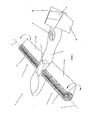
- Aircraft 1 has a fuselage 2, and opposing wings or aerofoils 3, 4 either side of the fuselage 2. Each wing 3, 4 supports a tangential flow rotor 5 having a rotational axis "X". The tangential flow rotor is housed within a rotor cavity.
- Wing 3 has a tail section 3A forming a wing trailing edge.
- Tail section 3A is moveable about the rotor axis "X" relative to the fuselage 2.
- wing 4 has a tail section 4A forming a wing trailing edge.
- Tail sections 3A, 4A are moveable about the rotor axis "X" relative to the fuselage 1, thereby providing, in use of the aircraft, variable thrust vectors to create aircraft lift and forward movement as more fully described below.
- each tail section is used, inter alia, to control flight of the vehicle, especially to allow the aircraft forward flight as well as vertical take off.
- Movement of the tail section in addition to providing lift can be used to control "roll" of the aircraft.
- a vertical axis fan 6 is provided on the fuselage 2 to adjust aircraft "pitch".
- Rear tail wings 8A, 8B and rudder 9 may also be provided.
- an aircraft comprising: a fuselage, opposing wings either side of the fuselage, each wing supporting at least one tangential flow rotor having a rotational axis, and at least one tail section for each wing forming a wing trailing edge, said tail section being moveable about the or each rotor axis relative to the fuselage so as to provide, in use of said aircraft, variable thrust vectors, whereby in use, movement of the or each tail section being used controls flight of the aircraft and a vertical axis fan located in the tail section and adapted to provide pitch control.
- a motor or engine 7 is provided to rotate each flow rotor 5.
- a magnetic field may be established so that on passing an electric current through the rotor, the rotor rotates.
- an electric or magnetic field can be established by inductive coupling.
- Other drive systems include a turbo prop engine, jet engine or conventional piston driven engine.
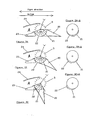
- a tail section 10 (which may be used as the tail section 3A or 4A in Figure 1 ) includes a curved surface or cowl 11 which covers a proportion of the circumference of a clockwise-rotating tangential flow rotor 5 which creates airflow over the top of the tail section 10 to deliver flight thrust in the opposite direction.
- the curved surface or cowl may have a radius of curvature substantially equal to the radius of curvature of the rotor 5.
- Tail section 10 includes a shroud 12 extending therefrom.
- Shroud 12 includes a curved surface or cowl which covers a proportion of the circumference of the rotor.
- the shroud 12 is fixed to and forms an extension to the tail section curved surface or cowl 11 to jointly cover a proportion of the circumference of the rotor and again has a radius of curvature substantially equal to the radius of curvature of the rotor.
- the shroud 12 and tail section curved surface or cowl 11 create a vortex chamber generally within the rotor.
- the curve of the shroud 12 and surface 11 could be offset relative to the curved circumference of the rotor (as shown with reference to Figures 3A-A - 3C-A below).
- the tail section 10 and shroud 11 are moveable about the rotor axis "X" relative to the fuselage such as shown in Figures 2A to 2C whereby to provide, in use of the aircraft, variable thrust vectors.
- the position shown in Figure 2A would provided forward thrust with some lift to the aircraft (e.g. during normal flight), the position shown in Figure 2B would provide forward thrust and lift to the aircraft (e.g. for slower flight), and the position shown in Figure 2C provides vertical lift to the aircraft.
- a tail section 20 (which may be used as the tail section 3A or 4A in Figure 1 ) includes a curved surface 21 which covers a proportion of the circumference of a tangential flow rotor 5.
- the curved surface 21 may have a radius of curvature substantially equal to the radius of curvature of the rotor 5.
- the curved surface 21 of the tail section 20 may be offset relative to the curved circumference of the rotor as shown in Figure 3A-A, 3B-A and 3C-A .
- the shroud reduces the angle of coverage of the rotor, this firstly increases the velocity of the vortex and secondly the air output angle is altered. As a result the fan efficiency is increased thus making the fan more suitable for hovering or vertical take off.
- Tail section 20 includes a shroud 22 extending therefrom.
- Shroud 22 includes a curved surface which covers a proportion of the circumference of the rotor.
- the shroud 22 has one end fixed to a lower air input duct member 23 on the wing and the other end overlaps the tail section 20 and slides over it.
- the proportion of the circumference of the rotor covered by the shroud 22 curved surface and tail section curved surface 21 varies as the tail section 20 moves about the rotor axis "X" as shown in Figures 3A to 3C .
- the radius of curvature of the shroud 22 curved surface changes as the tail section 20 moves about the or each rotor axis, and the radius of curvature of the shroud curved surface is non-uniform along its length.
- the shroud 22 and tail section curved surface 21 create a vortex chamber generally within the rotor having a vortex boundary defined by the combined length of the shroud 22 and tail section curved surface 21.
- the shape of the vortex may also change by changes in shape of the gap between the shroud 22 and curved surface 21 and the circumference of the rotor.
- the tail section 20 and shroud 22 when moved about the rotor axis "X" relative to the fuselage such as shown in Figures 3A to 3C provide, in use of the aircraft, variable thrust vectors.
- Lower air input duct member 23, in combination with an upper air input duct member 24 create a wing leading edge in the form of an air input duct "A" to allow passage of air to said rotor.
- the upper and lower air input duct members may be moved towards or away from each other so that the input duct "A" is variable in size to control the amount of air passing therethrough, whereby to control "roll" of the aircraft.
- the position shown in Figure 3A would provided forward thrust with some lift to the aircraft (e.g. during normal flight).
- air enters the wing through the input duct "A" flowing between the members 23, 24 to be accelerated by rotor 5 rotating clockwise over the vortex in the rotor.
- the air is ejected over the tail section 20.
- the angle formed between the opposing ends of the shroud 22 and axis "X" and curved section 21 and axis "X” may be about 160°.
- the radius of curvature of the shroud 22 and curved section is similar to that of the circumference of the rotor although it is moved away from the motor radially by 10 to 20% of the radius.
- the position shown in Figure 3B would provide forward thrust and lift to the aircraft (e.g. for slower flight).
- air enters the wing through the input duct "A" flowing between the members 23,24 to be accelerated by rotor 5 rotating clockwise over the vortex in the rotor.
- the air is ejected over the tail section 20.
- the angle formed between the opposing ends of the shroud 22 and axis "X" and curved section 21 and axis "X” may be about 130°.
- the combined length of the shroud 22 and tail section curved surface 21 is shorter than in Figure 3A , and the radius of curvature of the shroud 22 changes.
- the position shown in Figure 3C would provide vertical lift to the aircraft.
- air enters the wing through the input duct "A" flowing between the members 23,24 to be accelerated by rotor 5 rotating clockwise over the vortex in the rotor.
- the air is ejected over the tail section 20.
- the angle formed between the opposing ends of the shroud 22 and axis "X" and curved section 21 and axis "X” may be about 80° - 90°, e.g. 85°.
- the combined length of the shroud 22 and tail section curved surface 21 is shorter than in Figure 3B and the radius of curvature increases still further.
- each wing could support two or more rotors, e.g. axially aligned in side by side relationship.
- each wing could support two or more tail sections.
- the shroud of Figures 3A to 3C could slide over the curved section 21 of tail section 20 rather than the face of tail section 20 shown.
- differential drive of the rotors with respect to one another permits the aircraft to bank to permit turning.
- the aircraft may be an unmanned vehicle such as a Drone or unmanned aerial vehicle (UAV).
- UAV unmanned aerial vehicle
Landscapes
- Engineering & Computer Science (AREA)
- Aviation & Aerospace Engineering (AREA)
- Structures Of Non-Positive Displacement Pumps (AREA)
- Compositions Of Oxide Ceramics (AREA)
- Other Liquid Machine Or Engine Such As Wave Power Use (AREA)
- Force Measurement Appropriate To Specific Purposes (AREA)
- Tires In General (AREA)
- Braking Arrangements (AREA)
Claims (10)
- Luftfahrzeug (1), umfassend: einen Rumpf (2), einander gegenüberliegende Flügel (3, 4) auf beiden Seiten des Rumpfes (2), wobei jeder Flügel (3, 4) mindestens einen Tangentialstromrotor (5) mit einer Drehachse (X) stützt, mindestens einen Heckabschnitt (20) für jeden Flügel (3, 4), der eine Flügelaustrittskante und ein Mittel zur Drehung des oder jedes Heckabschnitts (20) um die oder jede Drehachse (X) bezüglich des Rumpfes (2) bildet, um Vorwärtsflug des Luftfahrzeugs (1) sowie Senkrechtstart zu gestatten, dadurch gekennzeichnet, dass der oder jeder Heckabschnitt (20) eine Verkleidung (22) enthält, die sich davon erstreckt, wobei jeder Heckabschnitt (20) und jede Verkleidung (22) jeweils eine gekrümmte Fläche (21, 22) enthalten, die einen Teil des Umfangs des Rotors (5) bedeckt, und dass die Verkleidung (22) mit einem festen Punkt auf einem Flügel verbunden ist und dazu angeordnet ist, über einen Abschnitt des Heckabschnitts (20) so zu gleiten, dass der durch die gekrümmte Fläche (22) der Verkleidung und die gekrümmte Fläche (21) des Heckabschnitts bedeckte Teil des Umfangs des Rotors (5) verringert wird, wenn sich der entsprechende Heckabschnitt (20) um die oder jede Drehachse (X) nach unten dreht.
- Luftfahrzeug nach Anspruch 1, wobei die gekrümmte Fläche (22) der Verkleidung einen Krümmungsradius aufweist, der sich ändert, wenn sich der entsprechende Heckabschnitt (20) um die oder jede Drehachse bewegt.
- Luftfahrzeug nach Anspruch 1, wobei die gekrümmte Fläche der Verkleidung einen Krümmungsradius aufweist, der über seine Länge nicht gleichförmig ist.
- Luftfahrzeug nach einem vorhergehenden Anspruch, wobei sich die oder jede gekrümmte Fläche (21) des Heckabschnitts um mindestens 25% des Umfangs des Rotors (5) und vorzugsweise 40% des Umfangs des Rotors (5) erstreckt.
- Luftfahrzeug nach einem vorhergehenden Anspruch, wobei die gekrümmte Fläche (21) des Heckabschnitts einen Krümmungsradius aufweist, der im Wesentlichen gleich dem Krümmungsradius des Rotors (5) ist.
- Luftfahrzeug nach einem vorhergehenden Anspruch, wobei die gekrümmte Fläche (21) des Heckabschnitts bezüglich des gekrümmten Umfangs des Rotors (5) versetzt ist.
- Luftfahrzeug nach einem vorhergehenden Anspruch, wobei der Heckabschnitt (20) und die Verkleidung (22) bezüglich einander und um die oder jede Rotorachse bezüglich des Rumpfes beweglich sind.
- Luftfahrzeug nach einem vorhergehenden Anspruch, wobei eine Flügeleintrittskante für jeden Flügel in Form eines Lufteingangskanals (A) vorgesehen ist, um ein Durchströmen von Luft zu dem Rotor (5) zu gestatten.
- Luftfahrzeug nach Anspruch 8, wobei die Größe des Kanals (A) variabel ist, um die dort hindurch strömende Luftmenge und dadurch das "Rollen" des Luftfahrzeugs zu steuern.
- Luftfahrzeug nach einem vorhergehenden Anspruch, wobei ein Vertikalachsenlüfter (6) am Rumpf (2) oder in der Nähe des rückwärtigen Teils davon vorgesehen ist, um das "Nicken" des Flugzeugs zu steuern.
Applications Claiming Priority (2)
| Application Number | Priority Date | Filing Date | Title |
|---|---|---|---|
| GBGB0606518.9A GB0606518D0 (en) | 2006-03-31 | 2006-03-31 | Aircraft with aerodynamic lift generating device |
| PCT/GB2007/001186 WO2007113525A2 (en) | 2006-03-31 | 2007-04-02 | Aircraft with aerodynamic lift generating device |
Publications (3)
| Publication Number | Publication Date |
|---|---|
| EP2004484A2 EP2004484A2 (de) | 2008-12-24 |
| EP2004484B1 true EP2004484B1 (de) | 2010-05-05 |
| EP2004484B8 EP2004484B8 (de) | 2010-06-16 |
Family
ID=36425004
Family Applications (1)
| Application Number | Title | Priority Date | Filing Date |
|---|---|---|---|
| EP07732240A Not-in-force EP2004484B8 (de) | 2006-03-31 | 2007-04-02 | Luftfahrzeug mit einer vorrichtung zur erzeugung einer aerodynamischen auftriebskraft |
Country Status (10)
| Country | Link |
|---|---|
| US (1) | US8448905B2 (de) |
| EP (1) | EP2004484B8 (de) |
| CN (1) | CN101405182B (de) |
| AT (1) | ATE466766T1 (de) |
| AU (1) | AU2007232413B2 (de) |
| CA (1) | CA2682372C (de) |
| DE (1) | DE602007006292D1 (de) |
| GB (1) | GB0606518D0 (de) |
| IL (1) | IL194268A (de) |
| WO (1) | WO2007113525A2 (de) |
Cited By (2)
| Publication number | Priority date | Publication date | Assignee | Title |
|---|---|---|---|---|
| DE202012005031U1 (de) | 2012-05-19 | 2012-07-06 | Wolfgang Richter | Vorrichtung zur Erhöhung der Auftriebs- oder Reaktionskraft an einem aerodynamisch geformten Flügel |
| CN104773286A (zh) * | 2015-05-08 | 2015-07-15 | 佛山市神风航空科技有限公司 | 一种机械传动滚筒翼升力生成装置 |
Families Citing this family (23)
| Publication number | Priority date | Publication date | Assignee | Title |
|---|---|---|---|---|
| CN102267559A (zh) * | 2011-04-24 | 2011-12-07 | 王志成 | 动面翼 |
| CN102358423B (zh) * | 2011-09-21 | 2014-04-16 | 陈晓春 | 贯流式空气悬浮平台 |
| WO2013040847A1 (zh) * | 2011-09-21 | 2013-03-28 | Chen Xiaochun | 贯流式空气悬浮平台 |
| KR101145960B1 (ko) | 2011-12-16 | 2012-05-15 | 장성호 | 비행체의 수직 이착륙 장치 |
| BG111231A (en) * | 2012-06-07 | 2013-12-31 | КРЪСТЕВ ИванKrustev Ivan | ROAD-AIR VEHICLE |
| US9187175B1 (en) * | 2013-10-31 | 2015-11-17 | Franklin Y. K. Chen | Flying-wing and VTOL flying-wing aircraft |
| DE202014001643U1 (de) | 2014-02-21 | 2014-03-20 | Joscha Metzger | Bodeneffektfahrzeug mit verbesserter An-und Auftriebsvorrichtung |
| CN104401485A (zh) * | 2014-10-13 | 2015-03-11 | 南京航空航天大学 | 四扇翼无人飞行器及控制方法 |
| CN104477373B (zh) * | 2014-12-15 | 2016-08-31 | 佛山市神风航空科技有限公司 | 一种半转机构升力翼低速飞机 |
| CN104494807B (zh) * | 2014-12-15 | 2016-11-09 | 佛山市神风航空科技有限公司 | 一种高升力机翼 |
| CN104760688B (zh) * | 2015-05-08 | 2016-06-29 | 佛山市神风航空科技有限公司 | 一种往复直线运动滚筒翼升力生成装置 |
| CN104760687B (zh) * | 2015-05-08 | 2016-11-16 | 佛山市神风航空科技有限公司 | 一种翼尖风球式滚筒翼升力生成装置 |
| CN104986323B (zh) * | 2015-06-23 | 2017-07-11 | 中国航空工业集团公司西安飞机设计研究所 | 一种扇翼飞机 |
| CN104890872B (zh) * | 2015-06-23 | 2017-06-16 | 中国航空工业集团公司西安飞机设计研究所 | 一种扇翼飞机用整流装置及具有其的飞机 |
| US10633090B2 (en) * | 2016-03-17 | 2020-04-28 | United Technologies Corporation | Cross flow fan with exit guide vanes |
| TWI599390B (zh) * | 2016-06-27 | 2017-09-21 | 邱南昌 | 多軸飛行器用風阻抗風器 |
| US11325697B1 (en) * | 2016-07-18 | 2022-05-10 | Franklin Y. K. Chen | VTOL flying wing and flying wing aircraft |
| US10421541B2 (en) * | 2016-08-10 | 2019-09-24 | Bell Helicopter Textron Inc. | Aircraft with tilting cross-flow fan wings |
| US10377480B2 (en) | 2016-08-10 | 2019-08-13 | Bell Helicopter Textron Inc. | Apparatus and method for directing thrust from tilting cross-flow fan wings on an aircraft |
| US10479495B2 (en) | 2016-08-10 | 2019-11-19 | Bell Helicopter Textron Inc. | Aircraft tail with cross-flow fan systems |
| RU174731U1 (ru) * | 2017-03-07 | 2017-10-30 | Борис Яковлевич Тузов | Гибридный экранолет |
| CN108860599A (zh) * | 2018-06-19 | 2018-11-23 | 温和 | 一种辊筒扇翼 |
| KR102449142B1 (ko) * | 2021-01-08 | 2022-09-29 | 주식회사 엠지아이티 | 수직이착륙형 드론 및 수직이착륙형 드론의 수직 이착륙 및 비행 전환을 위한 구동 방법 |
Family Cites Families (12)
| Publication number | Priority date | Publication date | Assignee | Title |
|---|---|---|---|---|
| US1875276A (en) * | 1932-08-30 | Airckaft of the heavier than air type | ||
| US1487228A (en) * | 1924-01-25 | 1924-03-18 | Garcia Emilio | Aeroplane |
| US2050903A (en) * | 1934-11-19 | 1936-08-11 | Topliff Oliver | Airplane drive |
| US2344515A (en) * | 1941-01-17 | 1944-03-21 | Henry P Massey | Means and method for increasing the magnus effect |
| US2397189A (en) * | 1942-09-07 | 1946-03-26 | David W Main | Airplane |
| GB885666A (en) * | 1956-12-07 | 1961-12-28 | Laing Nikolaus | Improvements in aircraft wings |
| US3140065A (en) * | 1962-06-27 | 1964-07-07 | Alvarez-Calderon Alberto | High lift and control system for aircraft |
| DE2820355C2 (de) * | 1978-05-10 | 1984-02-02 | Jastram-Werke Gmbh Kg, 2050 Hamburg | Ruder für Wasserfahrzeuge und schwimmendes Gerät |
| GB2316374A (en) * | 1996-08-20 | 1998-02-25 | Patrick Peebles | Fluid dynamic lift generation |
| GB9902653D0 (en) * | 1999-02-05 | 1999-03-31 | Peebles Patrick | Aerodynamic lift generating device |
| US7461811B2 (en) * | 2002-09-11 | 2008-12-09 | Milde Jr Karl F | VTOL personal aircraft |
| US7654486B2 (en) * | 2002-09-11 | 2010-02-02 | Milde Jr Karl F | VTOL personal aircraft |
-
2006
- 2006-03-31 GB GBGB0606518.9A patent/GB0606518D0/en not_active Ceased
-
2007
- 2007-04-02 EP EP07732240A patent/EP2004484B8/de not_active Not-in-force
- 2007-04-02 AT AT07732240T patent/ATE466766T1/de not_active IP Right Cessation
- 2007-04-02 CA CA2682372A patent/CA2682372C/en not_active Expired - Fee Related
- 2007-04-02 AU AU2007232413A patent/AU2007232413B2/en not_active Ceased
- 2007-04-02 DE DE602007006292T patent/DE602007006292D1/de active Active
- 2007-04-02 US US12/225,589 patent/US8448905B2/en not_active Expired - Fee Related
- 2007-04-02 CN CN2007800103275A patent/CN101405182B/zh not_active Expired - Fee Related
- 2007-04-02 WO PCT/GB2007/001186 patent/WO2007113525A2/en not_active Ceased
-
2008
- 2008-09-22 IL IL194268A patent/IL194268A/en not_active IP Right Cessation
Cited By (2)
| Publication number | Priority date | Publication date | Assignee | Title |
|---|---|---|---|---|
| DE202012005031U1 (de) | 2012-05-19 | 2012-07-06 | Wolfgang Richter | Vorrichtung zur Erhöhung der Auftriebs- oder Reaktionskraft an einem aerodynamisch geformten Flügel |
| CN104773286A (zh) * | 2015-05-08 | 2015-07-15 | 佛山市神风航空科技有限公司 | 一种机械传动滚筒翼升力生成装置 |
Also Published As
| Publication number | Publication date |
|---|---|
| WO2007113525A3 (en) | 2007-11-29 |
| WO2007113525A2 (en) | 2007-10-11 |
| DE602007006292D1 (de) | 2010-06-17 |
| EP2004484B8 (de) | 2010-06-16 |
| IL194268A (en) | 2012-01-31 |
| US8448905B2 (en) | 2013-05-28 |
| GB0606518D0 (en) | 2006-05-10 |
| CA2682372A1 (en) | 2007-10-11 |
| US20110101173A1 (en) | 2011-05-05 |
| AU2007232413A1 (en) | 2007-10-11 |
| AU2007232413B2 (en) | 2013-01-17 |
| CN101405182A (zh) | 2009-04-08 |
| CA2682372C (en) | 2016-06-07 |
| CN101405182B (zh) | 2012-10-10 |
| ATE466766T1 (de) | 2010-05-15 |
| EP2004484A2 (de) | 2008-12-24 |
Similar Documents
| Publication | Publication Date | Title |
|---|---|---|
| EP2004484B1 (de) | Luftfahrzeug mit einer vorrichtung zur erzeugung einer aerodynamischen auftriebskraft | |
| EP3363732B1 (de) | Ejektor und tragflächenkonfigurationen | |
| US20040026563A1 (en) | Vertical take-off and landing vehicles | |
| US20240051655A1 (en) | System and method for lift augmentation of aircraft wings | |
| EP1551708A1 (de) | Senkrecht startendes und landendes flugzeug | |
| EP3587261B1 (de) | Blended-wing-body-flugzeug | |
| CN1531496A (zh) | 用于旋翼式飞机的抗扭矩和偏航控制系统 | |
| US12037110B2 (en) | Rotary wing aircraft with a shrouded tail propeller | |
| EP4011765B1 (de) | Drehflügelflugzeug mit asymmetrischem heckteil | |
| EP1592613A1 (de) | Drehmomentausgleichs- und seitensteuerungssystem für einen drehflügler | |
| EP3914513B1 (de) | Flugzeug | |
| US11697493B2 (en) | Rotary wing aircraft with a shrouded tail propeller | |
| EP4011766B1 (de) | Drehflügelflugzeug mit einem asymmetrischen vorderteil | |
| EP4387893B1 (de) | Ein system für auftrieb, antrieb und steuerung eines luftfahrzeugs | |
| EP3722208B1 (de) | Aktives hochauftriebssystem für kurz startende und landende (stol) luftfahrzeuge | |
| WO2026044335A1 (en) | Unmanned aerial system | |
| CN121152751A (zh) | 垂直起降航空器及其操纵方法与控制装置 |
Legal Events
| Date | Code | Title | Description |
|---|---|---|---|
| PUAI | Public reference made under article 153(3) epc to a published international application that has entered the european phase |
Free format text: ORIGINAL CODE: 0009012 |
|
| 17P | Request for examination filed |
Effective date: 20081031 |
|
| AK | Designated contracting states |
Kind code of ref document: A2 Designated state(s): AT BE BG CH CY CZ DE DK EE ES FI FR GB GR HU IE IS IT LI LT LU LV MC MT NL PL PT RO SE SI SK TR |
|
| 17Q | First examination report despatched |
Effective date: 20090223 |
|
| GRAP | Despatch of communication of intention to grant a patent |
Free format text: ORIGINAL CODE: EPIDOSNIGR1 |
|
| DAX | Request for extension of the european patent (deleted) | ||
| GRAS | Grant fee paid |
Free format text: ORIGINAL CODE: EPIDOSNIGR3 |
|
| GRAA | (expected) grant |
Free format text: ORIGINAL CODE: 0009210 |
|
| AK | Designated contracting states |
Kind code of ref document: B1 Designated state(s): AT BE BG CH CY CZ DE DK EE ES FI FR GB GR HU IE IS IT LI LT LU LV MC MT NL PL PT RO SE SI SK TR |
|
| REG | Reference to a national code |
Ref country code: GB Ref legal event code: FG4D |
|
| REG | Reference to a national code |
Ref country code: CH Ref legal event code: EP |
|
| REG | Reference to a national code |
Ref country code: IE Ref legal event code: FG4D |
|
| RAP2 | Party data changed (patent owner data changed or rights of a patent transferred) |
Owner name: FANWING LIMITED |
|
| REF | Corresponds to: |
Ref document number: 602007006292 Country of ref document: DE Date of ref document: 20100617 Kind code of ref document: P |
|
| REG | Reference to a national code |
Ref country code: NL Ref legal event code: VDEP Effective date: 20100505 |
|
| LTIE | Lt: invalidation of european patent or patent extension |
Effective date: 20100505 |
|
| PG25 | Lapsed in a contracting state [announced via postgrant information from national office to epo] |
Ref country code: LT Free format text: LAPSE BECAUSE OF FAILURE TO SUBMIT A TRANSLATION OF THE DESCRIPTION OR TO PAY THE FEE WITHIN THE PRESCRIBED TIME-LIMIT Effective date: 20100505 Ref country code: ES Free format text: LAPSE BECAUSE OF FAILURE TO SUBMIT A TRANSLATION OF THE DESCRIPTION OR TO PAY THE FEE WITHIN THE PRESCRIBED TIME-LIMIT Effective date: 20100816 Ref country code: SE Free format text: LAPSE BECAUSE OF FAILURE TO SUBMIT A TRANSLATION OF THE DESCRIPTION OR TO PAY THE FEE WITHIN THE PRESCRIBED TIME-LIMIT Effective date: 20100505 Ref country code: NL Free format text: LAPSE BECAUSE OF FAILURE TO SUBMIT A TRANSLATION OF THE DESCRIPTION OR TO PAY THE FEE WITHIN THE PRESCRIBED TIME-LIMIT Effective date: 20100505 |
|
| PG25 | Lapsed in a contracting state [announced via postgrant information from national office to epo] |
Ref country code: LV Free format text: LAPSE BECAUSE OF FAILURE TO SUBMIT A TRANSLATION OF THE DESCRIPTION OR TO PAY THE FEE WITHIN THE PRESCRIBED TIME-LIMIT Effective date: 20100505 Ref country code: AT Free format text: LAPSE BECAUSE OF FAILURE TO SUBMIT A TRANSLATION OF THE DESCRIPTION OR TO PAY THE FEE WITHIN THE PRESCRIBED TIME-LIMIT Effective date: 20100505 Ref country code: FI Free format text: LAPSE BECAUSE OF FAILURE TO SUBMIT A TRANSLATION OF THE DESCRIPTION OR TO PAY THE FEE WITHIN THE PRESCRIBED TIME-LIMIT Effective date: 20100505 Ref country code: SI Free format text: LAPSE BECAUSE OF FAILURE TO SUBMIT A TRANSLATION OF THE DESCRIPTION OR TO PAY THE FEE WITHIN THE PRESCRIBED TIME-LIMIT Effective date: 20100505 Ref country code: IS Free format text: LAPSE BECAUSE OF FAILURE TO SUBMIT A TRANSLATION OF THE DESCRIPTION OR TO PAY THE FEE WITHIN THE PRESCRIBED TIME-LIMIT Effective date: 20100905 |
|
| PG25 | Lapsed in a contracting state [announced via postgrant information from national office to epo] |
Ref country code: CY Free format text: LAPSE BECAUSE OF FAILURE TO SUBMIT A TRANSLATION OF THE DESCRIPTION OR TO PAY THE FEE WITHIN THE PRESCRIBED TIME-LIMIT Effective date: 20100602 Ref country code: PL Free format text: LAPSE BECAUSE OF FAILURE TO SUBMIT A TRANSLATION OF THE DESCRIPTION OR TO PAY THE FEE WITHIN THE PRESCRIBED TIME-LIMIT Effective date: 20100505 |
|
| PG25 | Lapsed in a contracting state [announced via postgrant information from national office to epo] |
Ref country code: DK Free format text: LAPSE BECAUSE OF FAILURE TO SUBMIT A TRANSLATION OF THE DESCRIPTION OR TO PAY THE FEE WITHIN THE PRESCRIBED TIME-LIMIT Effective date: 20100505 Ref country code: EE Free format text: LAPSE BECAUSE OF FAILURE TO SUBMIT A TRANSLATION OF THE DESCRIPTION OR TO PAY THE FEE WITHIN THE PRESCRIBED TIME-LIMIT Effective date: 20100505 Ref country code: PT Free format text: LAPSE BECAUSE OF FAILURE TO SUBMIT A TRANSLATION OF THE DESCRIPTION OR TO PAY THE FEE WITHIN THE PRESCRIBED TIME-LIMIT Effective date: 20100906 |
|
| PG25 | Lapsed in a contracting state [announced via postgrant information from national office to epo] |
Ref country code: SK Free format text: LAPSE BECAUSE OF FAILURE TO SUBMIT A TRANSLATION OF THE DESCRIPTION OR TO PAY THE FEE WITHIN THE PRESCRIBED TIME-LIMIT Effective date: 20100505 Ref country code: BE Free format text: LAPSE BECAUSE OF FAILURE TO SUBMIT A TRANSLATION OF THE DESCRIPTION OR TO PAY THE FEE WITHIN THE PRESCRIBED TIME-LIMIT Effective date: 20100505 Ref country code: CZ Free format text: LAPSE BECAUSE OF FAILURE TO SUBMIT A TRANSLATION OF THE DESCRIPTION OR TO PAY THE FEE WITHIN THE PRESCRIBED TIME-LIMIT Effective date: 20100505 Ref country code: RO Free format text: LAPSE BECAUSE OF FAILURE TO SUBMIT A TRANSLATION OF THE DESCRIPTION OR TO PAY THE FEE WITHIN THE PRESCRIBED TIME-LIMIT Effective date: 20100505 |
|
| PLBE | No opposition filed within time limit |
Free format text: ORIGINAL CODE: 0009261 |
|
| STAA | Information on the status of an ep patent application or granted ep patent |
Free format text: STATUS: NO OPPOSITION FILED WITHIN TIME LIMIT |
|
| 26N | No opposition filed |
Effective date: 20110208 |
|
| REG | Reference to a national code |
Ref country code: DE Ref legal event code: R097 Ref document number: 602007006292 Country of ref document: DE Effective date: 20110207 |
|
| PG25 | Lapsed in a contracting state [announced via postgrant information from national office to epo] |
Ref country code: GR Free format text: LAPSE BECAUSE OF FAILURE TO SUBMIT A TRANSLATION OF THE DESCRIPTION OR TO PAY THE FEE WITHIN THE PRESCRIBED TIME-LIMIT Effective date: 20100806 |
|
| PG25 | Lapsed in a contracting state [announced via postgrant information from national office to epo] |
Ref country code: MC Free format text: LAPSE BECAUSE OF NON-PAYMENT OF DUE FEES Effective date: 20110430 |
|
| REG | Reference to a national code |
Ref country code: CH Ref legal event code: PL |
|
| PG25 | Lapsed in a contracting state [announced via postgrant information from national office to epo] |
Ref country code: MT Free format text: LAPSE BECAUSE OF FAILURE TO SUBMIT A TRANSLATION OF THE DESCRIPTION OR TO PAY THE FEE WITHIN THE PRESCRIBED TIME-LIMIT Effective date: 20100505 |
|
| PG25 | Lapsed in a contracting state [announced via postgrant information from national office to epo] |
Ref country code: CH Free format text: LAPSE BECAUSE OF NON-PAYMENT OF DUE FEES Effective date: 20110430 Ref country code: LI Free format text: LAPSE BECAUSE OF NON-PAYMENT OF DUE FEES Effective date: 20110430 |
|
| REG | Reference to a national code |
Ref country code: IE Ref legal event code: MM4A |
|
| PG25 | Lapsed in a contracting state [announced via postgrant information from national office to epo] |
Ref country code: IE Free format text: LAPSE BECAUSE OF NON-PAYMENT OF DUE FEES Effective date: 20110402 |
|
| PG25 | Lapsed in a contracting state [announced via postgrant information from national office to epo] |
Ref country code: LU Free format text: LAPSE BECAUSE OF NON-PAYMENT OF DUE FEES Effective date: 20110402 |
|
| PG25 | Lapsed in a contracting state [announced via postgrant information from national office to epo] |
Ref country code: BG Free format text: LAPSE BECAUSE OF FAILURE TO SUBMIT A TRANSLATION OF THE DESCRIPTION OR TO PAY THE FEE WITHIN THE PRESCRIBED TIME-LIMIT Effective date: 20100805 Ref country code: TR Free format text: LAPSE BECAUSE OF FAILURE TO SUBMIT A TRANSLATION OF THE DESCRIPTION OR TO PAY THE FEE WITHIN THE PRESCRIBED TIME-LIMIT Effective date: 20100505 |
|
| PG25 | Lapsed in a contracting state [announced via postgrant information from national office to epo] |
Ref country code: HU Free format text: LAPSE BECAUSE OF FAILURE TO SUBMIT A TRANSLATION OF THE DESCRIPTION OR TO PAY THE FEE WITHIN THE PRESCRIBED TIME-LIMIT Effective date: 20100505 |
|
| REG | Reference to a national code |
Ref country code: FR Ref legal event code: PLFP Year of fee payment: 10 |
|
| REG | Reference to a national code |
Ref country code: FR Ref legal event code: PLFP Year of fee payment: 11 |
|
| PGFP | Annual fee paid to national office [announced via postgrant information from national office to epo] |
Ref country code: FR Payment date: 20170329 Year of fee payment: 11 |
|
| PGFP | Annual fee paid to national office [announced via postgrant information from national office to epo] |
Ref country code: GB Payment date: 20170323 Year of fee payment: 11 |
|
| PGFP | Annual fee paid to national office [announced via postgrant information from national office to epo] |
Ref country code: DE Payment date: 20170418 Year of fee payment: 11 |
|
| PGFP | Annual fee paid to national office [announced via postgrant information from national office to epo] |
Ref country code: IT Payment date: 20170407 Year of fee payment: 11 |
|
| REG | Reference to a national code |
Ref country code: DE Ref legal event code: R119 Ref document number: 602007006292 Country of ref document: DE |
|
| GBPC | Gb: european patent ceased through non-payment of renewal fee |
Effective date: 20180402 |
|
| PG25 | Lapsed in a contracting state [announced via postgrant information from national office to epo] |
Ref country code: DE Free format text: LAPSE BECAUSE OF NON-PAYMENT OF DUE FEES Effective date: 20181101 |
|
| PG25 | Lapsed in a contracting state [announced via postgrant information from national office to epo] |
Ref country code: GB Free format text: LAPSE BECAUSE OF NON-PAYMENT OF DUE FEES Effective date: 20180402 |
|
| PG25 | Lapsed in a contracting state [announced via postgrant information from national office to epo] |
Ref country code: IT Free format text: LAPSE BECAUSE OF NON-PAYMENT OF DUE FEES Effective date: 20180402 Ref country code: FR Free format text: LAPSE BECAUSE OF NON-PAYMENT OF DUE FEES Effective date: 20180430 |